1
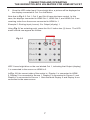
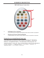
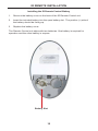
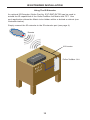
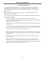
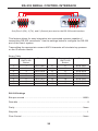
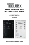
Gefen
4x4 Matrix for
HDMI® with FST
GTB-HDFST-444
GTB-HDFST-444-BLK
User Manual
www.gefentoolbox.com
ASKING FOR ASSISTANCE
Technical Support:
Telephone
Fax
(818) 772-9100
(800) 545-6900
(818) 772-9120
Technical Support Hours:
8:00 AM to 5:00 PM Monday thru Friday, Pacific Time
Write To:
Gefen, LLC.
c/o Customer Service
20600 Nordhoff St
Chatsworth, CA 91311
www.gefentoolbox.com
[email protected]
Notice
Gefen, LLC reserves the right to make changes in the hardware, packaging and
any accompanying documentation without prior written notice.
4x4 Matrix for HDMI with FST is a trademark of Gefen, LLC
HDMI, the
logo, and High-Definition Multimedia Interface are
trademarks or registered trademarks of HDMI Licensing in the United States and
other countries.
© 2010 Gefen, LLC, All Rights Reserved
All trademarks are the property of their respective owners
Rev A2
2.3p
CONTENTS
1
Introduction
2
Operation Notes
3
Features
4
Panel Layout
5
Panel Descriptions
6
Connecting And Operating The GefenToolBox 4x4 Matrix with FST
8
IR Remote Description
10 IR Remote Installation
11 IR Remote Configuration
12 Changing the IR Channel
13 IR Extender Installation
14 EDID Management
14
Understanding EDID
15
EDID Mode Selection
16
Audio Channel Selection
17
External EDID Management
18
Internal EDID Specification
19 FST Switching Technology
20 RS-232 Serial Control Interface
21 Wall Mounting Instructions
22 Specifications
23 Warranty
INTRODUCTION
Congratulations on your purchase of the GefenToolBox 4x4 Matrix with FST. Your
complete satisfaction is very important to us.
About Gefen
We specialize in total integration for your home theater, while also focusing on
going above and beyond customer expectations to ensure you get the most from
your hardware. We invite you to explore our distinct product line. Please visit
http://www.gefen.com for the latest offerings in High-Definition signal solutions
or call us between the hours of 8:00 am and 5:00 pm Monday-Friday, Pacific
Standard Time for assistance with your A/V needs. We’ll be happy to assist you.
Why GefenToolBox?
The GefenToolbox line offers portable and easy-to-install solutions for common
A/V system integration setups using HDMI connectivity. GefenToolBox products
are wall-mountable and small in size. GefenToolBox products are easily
transported in the field and are ready for immediate and simple installations in
working environments. These products come finished in a glossy color to blend in
with either a white wall or black cabinet.
The GefenToolBox 4x4 Matrix with FST
The GefenToolBox 4x4 Matrix with FST routes HDMI at resolutions up to 1080p
Full HD and 1920x1200@60Hz supporting multichannel digital audio from any
four Hi-Def sources to any four HDTV displays. The GefenToolBox 4x4 Matrix
eliminates the need to disconnect and reconnect HDMI sources. It works with
any HDMI source that needs to be connected to an HDTV display, supporting
digital audio formats such as Dolby TrueHD and DTS-HD Master Audio. Each
source is accessible at all times from any display by selecting it with the included
IR remote, the RS-232 port, or using the front-panel push buttons.
How It Works
Connect the Hi-Def A/V sources to the GefenToolBox 4x4 Matrix’s inputs using
the supplied HDMI cable. Connect up to 4 HDTV displays to the Matrix’s four
HDMI outputs using the provided HDMI cables. 3D content can be displayed
when connecting a 3DTV and 3D source. Apply power to sources and to the
displays. A/V Sources may now be routed to display devices by using the front
panel buttons or the included IR remote control unit.
1
OPERATION NOTES
READ THESE NOTES BEFORE INSTALLING OR
OPERATING THE GEFENTOOLBOX 4X4 MATRIX WITH FST
•
EDID contains the A/V capabilities of a display device in regards to video
resolutions and audio formats supported. This information is used by the
source device to determine the format of the A/V signal on the outputs.
The GefenToolBox 4x4 Matrix with FST incorporates advanced EDID
management to ensure compatibility with all sources and display devices.
Please see pages 14 - 18 for more details.
•
The GefenToolBox 4x4 Matrix with FST can detect the presence of Deep
Color (12-bit signal) automatically and will disable Deep Color EDID features
across all other outputs if any connected device or display is not capable
of processing Deep Color. This automatic behavior ensures compatibility
among all output devices in a mixed-device environment. This feature cannot
be disabled.
•
When powering the GefenToolBox 4x4 Matrix with FST or if the EDID
Mode is changed (see pages 4 - 5), the Matrix will undergo a momentary
initialization sequence. This is normal operation and may take a few
seconds.
2
FEATURES
Supported HDMI 1.3 Features
•
•
•
•
225 MHz (up to 12 bit YUV 444 @ 1080p)
Deep Color
Dolby TrueHD and DTS-HD Master Audio
Lip-Sync
General Features
•
Displays any of four (4) Hi-Def sources on any four (4) HDTV displays,
independently.
•
Maintains beautiful, sharp HDTV resolutions up to 1080p and 2K.
•
Supports 3DTV pass-through.
•
EDID Management for rapid integration of sources and display devices.
•
Fast Switching for quick and responsive HDMI signal routing. See page 19
for details.
•
Supports digital audio formats including LPCM 7.1 audio, Dolby Digital Plus,
Dolby TrueHD, and DTS-HD Master Audio.
•
Built-in IR Extender.
•
IR Remote Control.
•
RS-232 serial control.
•
Locking HDMI connections.
•
Firmware field-upgradable.
•
Wall-mountable.
•
This product is HDCP-compliant.
Package Includes
(1) GefenToolBox 4x4 Matrix with FST
(4) 6-foot Locking HDMI cable (M-M)
(1) 5V DC Locking Power Supply
(1) IR remote control
(1) User Manual
3
PANEL LAYOUT
Front Panel
1
12
2
3
4
11
5
10
Side Panel
6
7
8
9
4
PANEL DESCRIPTIONS
1
HDMI Input Ports 1-4
Connect HDMI source devices to these ports.
2
Fast / Slow Switch
Switches between Fast and Slow Switching. See page 19 for more information.
3
Audio Channel Selection Switch
This switch will modify the EDID to specify the number of supported audio
channels when using the INTERNAL EDID mode. This setting will not affect the
EDID information when using the EXTERNAL EDID mode.
4
EDID Mode Selection Switch
This switch will control the type of EDID used by the Matrix. The options are
EXTERNAL and INTERNAL. See page 15 for details.
5
Source Selectors (4) and Indicator LEDs (16)
The four (4) black buttons labeled “Out 1 - Out 4” select input sources 1 - 4 to
be mapped to the outputs 1 - 4. See pages 6 and 7 for more details on how to
use these buttons.
6
RS-232 Serial Port
Connects to the RS-232 control device. The 4x4 Matrix for HDMI may be
switched remotely using this port. See page 20 for details.
7
IR Extender Port
Connect an IR extender cable (Gefen part no. EXT-RMT-EXTIR) to this port.
See page 13 for details.
8
USB Service Port
Mini-USB service port used for upgrading the firmware.
9
5V DC Locking Power Connector
Connect the included 5V DC Locking Power Supply to this receptacle.
10 Power Indicator
This LED indicator will glow red when the unit is powered.
11 IR Window
Receives signals from the IR Remote Control unit.
12 HDMI Output Ports 1-4
Connect HDTV displays to these ports.
5
CONNECTING AND OPERATING
THE GEFENTOOLBOX 4X4 MATRIX FOR HDMI WITH FST
How to Connect the GefenToolBox 4x4 Matrix with FST
1.
Use one of the provided HDMI cables to connect the source device to the
HDMI input port of the GefenToolBox 4x4 Matrix with FST.
2.
Use additional HDMI cables to connect up to 4 HDMI cables to the four (4)
displays.
3.
Connect the included 5V DC locking power supply to the power receptacle
on the Matrix.
4.
Connect the other end of the power supply to an available power outlet.
How to Operate the GefenToolBox 4x4 Matrix with FST
The top panel of the GefenToolBox 4x4 Matrix with FST contains a set of LED
indicators, displaying which input (source) is routed to which output (display).
This allows for easy management and viewing of all input and output routing
states.
There are four (4) rows of LED indicators on the front panel. To the left of the
LED indicators are four push buttons: Out 1, Out 2, Out 3, and Out 4. The
numbers along the top of the LED matrix represent the currently selected Input
(source): 1, 2, 3, or 4.
Example 1: Routing Input (source) 2 to Output (display) 3
1.
Ensure that an HDMI cable is connected from the source to HDMI In 2 and
an HDMI cable is connected from the display to HDMI Out 3 on the Matrix.
2.
Press Out 3 Button on the row of black buttons running vertically until the
LED under Input 2 is bright blue. If the LED does not immediately appear
under Input 2, continue depressing the Out 3 button until the LED under
Input 2 turns bright blue (Fig 1.1).
Fig 1.1
6
CONNECTING AND OPERATING
THE GEFENTOOLBOX 4X4 MATRIX FOR HDMI WITH FST
3.
Once the LED under Input 2 turns bright blue, a picture will be displayed on
the display connected to Out 3 on the Matrix.
Note that in Fig 1.1, Out 1, Out 2, and Out 4 have also been routed. In this
case, the displays connected to HDMI Out 1, HDMI Out 2, and HDMI Out 3 are
receiving video from the source connected to HDMI In 1.
Example 2: Routing Input (source) 3 to Output (display) 1
Using Fig 1.1 as a starting point, press the Out 1 button two (2) times. The LED
matrix should now appear as follows:
Fig 1.2
LED 3 turns bright blue on the row labeled Out 1, indicating that Output (display)
1 is connected to the source on HDMI In 3.
In Fig. 1.2, the current state of the matrix is: Display 1 is connected to HDMI
2, Display 2 is connected to Source 1, Display 2 is connected to Source 2, and
Display 4 is connected to Source 1. Note that both Display 2 and Display 4 are
connected to the same source.
7
IR REMOTE DESCRIPTION
RMT-16IR Remote Control Unit
1
2
1
LED Button Press Indicator
This LED will be activated momentarily each time a button is pressed.
2
Display and Source Selection Buttons
These buttons are used to select which source is routed to a monitor.
Routing Sources using the Remote Control unit
There are a total of 16 buttons on the IR Remote Control unit. Each set of
colored buttons represents one of four Outputs on the Matrix: The first four
buttons (1 - 4) represent Output 1. The second set of four buttons (5 - 8)
represent Output 2, and so on. Each numbered button within that set represents
an input: Buttons 1 - 4 represent Inputs 1 - 4 on Output 1. Buttons 5 - 8
represent Inputs 1 - 4 on Output 2, and so on.
8
IR REMOTE DESCRIPTION
Example 1:
Route the source connected to In 3 to the display connected to Out 4.
1.
Press button 15 (Input 3) on the IR remote control unit.
The source connected to In 3 will be routed to the monitor connected to Out 4.
Use the table below when selecting the desired source for each display.
Table of IR Remote Commands
for the GefenToolBox 4x4 Matrix with FST
RMT-16IR button
11
Source
3
9
Display
3
IR REMOTE INSTALLATION
Installing the IR Remote Control Battery
1.
Remove the battery cover on the back of the IR Remote Control unit.
2.
Insert the included battery into the open battery slot. The positive (+) side of
the battery should be facing up.
3.
Replace the battery cover.
The Remote Control unit ships with two batteries. One battery is required for
operation and the other battery is a spare.
Battery Slot
10
IR REMOTE CONFIGURATION
Resolving IR Code Conflicts
In the event that IR commands from other remote controls conflict with the
supplied IR remote control unit, changing the remote channel will alleviate this
issue. The IR remote control unit has a bank of DIP switches for setting the
remote IR channel.
The DIP Switch bank on the IR remote control unit is located underneath the
battery cover.
DIP Switches
It is important that the IR channel selected on the remote, match the IR channel
on the GefenToolBox 4x4 Matrix with FST for proper operation. For example, if
you set both DIP switches on the remote to the down position (toward the “1” and
“2”), IR channel 0, you must set the GefenToolBox 4x4 Matrix with FST to use IR
channel 0.
Remote Channel 0:
Default
Remote Channel 1:
1
2
Remote Channel 2:
1
2
1
2
Remote Channel 3:
1
2
See page 12 for information on how to change the IR channel on the
GefenToolBox 4x4 Matrix with FST.
11
CHANGING THE IR CHANNEL
Setting The IR Channel on the Matrix
Use the following procedure to set the proper IR channel on the Matrix.
1
Press and hold the Out 1 button for 5 seconds to enter the IR channel
selection mode. The bank of blue LED indicators will now display the
currently selected IR channel.
2
Press the Out 1 button to cycle through each IR channel. The currently
selected IR channel will by indicated by a flashing blue LED.
IMPORTANT: The selected IR channel must be the same as the IR channel
set on the IR Remote (see page 11). Refer to the table below for setting the
IR channel.
3
Once the proper IR channel has been selected, press and hold the Out 1
button for 5 seconds to confirm and exit IR channel selection mode. The
currently selected input source will now be indicated.
IR Channel Table
Input LED
IR Channel
1
0
2
1
3
2
4
3
12
IR EXTENDER INSTALLATION
Using The IR Extender
An optional IR Extender (Gefen Part No. EXT-RMT-EXTIR) can be used to
extend the IR capabilities of the GefenToolBox 4x4 Matrix with FST. One
such application allows the Matrix to be hidden within or behind a cabinet (see
illustration below).
Simply connect the IR extender to the IR extender port (see page 4).
Remote
IR Extender
op
et-t
Box
S
Gefen Toolbox Unit
f
ko
Bac inet
b
Ca
13
EDID MANAGEMENT
Understanding EDID
The GefenToolBox 4x4 Matrix with FST features automatic and manual EDID
adjustments to maximize compatibility of all attached devices. First, it is
necessary to understand EDID and what it is used for.
EDID. What is it and what is it used for?
Under normal circumstances, source devices will require information about a
connected display device to assess what video resolutions and other features are
compatible with the output device. This required information is called the EDID
(Extended Display Information Data). Almost all types of output devices/displays
(computer monitor, HDTV, A/V receiver) will transmit EDID to a connected
source. The source will then read this EDID file and make the necessary
adjustments to the output signal to ensure that only compatible resolutions/
features are generated in the output signal.
Why is EDID so important with the GefenToolBox 4x4 Matrix with FST?
The GefenToolBox 4x4 Matrix with FST uses complex technology that routes
multiple input signals to multiple outputs. The source devices will require EDID to
read. Multiple devices/displays can be connected to the input and output ports on
the Matrix, each with their own EDID. Management of EDID is key to ensure that
maximum compatibility is maintained between all devices.
What options do I have to manage the EDID in the GefenToolBox 4x4 Matrix
with FST?
It is important to understand that the EDID contains much more than just
listings of supported video resolutions and audio formats. However, resolutions
and audio formats are the two key types of information that a user will need to
understand how to use these EDID management functions.
Common problems that a user may encounter while using the Matrix can be:
1.
Video may not be visible on all output devices/displays.
2.
Audio may not be heard on all output devices/displays.
These symptoms usually arise from video resolution / audio format
incompatibilities between the devices / displays connected to the outputs.
The GefenToolBox 4x4 Matrix with FST can use one of two methods to acquire
and retransmit an EDID to the A/V source device relaying information about the
output devices that are connected to it, thus ensuring compatibility.
14
EDID MANAGEMENT
EDID Mode Selection
•
EXTERNAL MODE:
To use this mode, set the EDID Mode Switch on the front panel to the EXT
position. In External EDID mode, the Matrix retrieves EDID data directly from
each connected A/V display device. The EDID data is then compiled and a
new EDID is created based on the highest-supported video resolution and
audio capabilities common to all displays. The new EDID is sent back to the
source device.
If insufficient EDID data is available from external display devices or EDIDrelated problems are encountered, Internal EDID Mode should be used to
provide a single compatible EDID for all connected devices.
•
INTERNAL MODE:
Internal EDID mode uses a preset EDID that is stored in the GefenToolBox
4x4 Matrix with FST from the factory. To use this mode, set the EDID Mode
Switch on the front panel to the INT position. All resolutions and audio
formats specified in this EDID will be passed to the source device. Many
common resolutions and audio formats are supported. For a complete listing
of the resolutions and audio formats listed in this EDID please see page 18.
NOTE: All other HDMI capable devices/displays connected to the output
ports MUST be compatible with at least one resolution/audio format specified
in this EDID. It is recommended to set, on the source device, a common
resolution and audio format shared by all attached devices/displays. This is
to ensure a compatible signal is outputted to all connected devices/displays.
15
EDID MANAGEMENT
Audio Channel Selection
The GefenToolBox 4x4 Matrix with FST features a switch that will modify the
supported audio formats listed in the pre-programmed EDID. This feature is
useful for limiting the output of the source device to either 2 or multi-channel
audio formats.
NOTE: This selector switch will only affect the pre-programmed EDID in the
INTERNAL (INT) EDID Mode.
The GefenToolBox 4x4 Matrix with FST can use either of the following settings
for audio format support:
•
2 Channel: This setting will limit the audio formats listed in the preprogrammed EDID to 2 channel LPCM. For a full listing of the audio formats
in this mode please see page 18.
To use this mode, set the Audio Selection Switch on the front panel to the 2
CH position.
This mode is useful in scenarios where all output devices/displays are HDTV
monitors that only support 2 channel LPCM. This setting will ensure that all
connected devices will receive and produce sound.
•
Multi-Channel: This setting will enable all common audio formats in the preprogrammed EDID. For a full listing of the audio formats in this mode please
see page 18.
To use this mode, set the Audio Selection Switch on the front panel to the
Multi CH position.
This mode is useful in scenarios where the output devices/displays are
varying devices (i.e. HDTV display and audio receivers). Please note that
sound may not be heard from all output devices/displays if a shared common
audio format is not used by the source device.
16
EDID MANAGEMENT
External EDID Management
The GefenToolBox 4x4 Matrix with FST features EDID Management. Before the
source can send video or audio signals to the display, the source devices reads
the EDID (Extended Display Identification Data) of each device connected to
an output. The EDID contains information about what type of AV data that the
source can send to each display.
The GefenToolBox 4x4 Matrix with FST routes multiple source signals to multiple
output devices. This involves reading EDID data from more than one device.
Management of the EDID data is important to maintain compatibility between all
devices.
Display Connections
•
If a display is not connected to Output 1, then no EDID changes are made,
meaning that the previous EDID information will be used. This state will be
in effect until a display is connected to Output 1 and the Matrix is powercycled.
•
EDID is copied from Output 1 to all other outputs. The audio block will be
copied from Output 1. EDID-copying is performed only when the Matrix is
reset or power-cycled.
3DTV Support
•
3D signals are supported if a 3DTV is connected to Output 1.
Deep Color
•
Deep Color will be disabled if one of more other displays connected to the
Matrix do not support Deep Color.
17
EDID MANAGEMENT
Internal EDID Specifications
The table below lists the settings that comprise the built-in Internal EDID data
structure:
Video Data Block
1080p@60Hz
Audio Data Block
Speaker Allocation
xvYCC
2-channel:
2-channel:
xvYCC 709
LPCM 2CH
FL/FR
xvYCC 601
Multi-channel:
Multi-Channel:
LPCM 2CH
LPCM 8CH
AC-3 6CH
DTS 7CH
Dolby Digital+ 8CH
Dolby TrueHD 8CH
DTS-HD 8CH
MAT(MLP) 8CH
RLC/RRC
RL/RR
FC
LFE
FL/FR
1080p@50Hz
1080i@60Hz (native)
1080i@50Hz
18
FAST SWITCHING TECHNOLOGY
FAST SWITCHING TECHNOLOGY
Fast Switching Technology
Fast Switching Technology (FST) is a Gefen software implementation for
HDMI 1.3 products. FST was created to improve the inherited lengthy HDMI
authentication process, based on the HDMI and HDCP specifications.
FST provides quicker A/V source switching and greatly improves the overall A/V
system behavior and performance when more than one HDTV display is used in
the system setup.
FST allows connecting / disconnecting or turning ON / OFF of HDTV displays
without having these activities affect other Hi-Def sources routed to any other
HDTV display in the same system.
FAST MODE:
Setting the Matrix to FAST mode will improve performance when routing sources,
powering ON / OFF HDTV displays, and disconnecting / connecting Hi-Def
sources.
NOTE: When switching from SLOW mode to FAST mode, the HDTV displays
connected to the Matrix will blink momentarily.
SLOW MODE:
When set to SLOW mode, the Matrix will follow the standard authentication
process, based on the HDMI and HDCP specifications. SLOW mode is
recommended when the source(s) does not support multiple devices.
19
RS-232 SERIAL CONTROL INTERFACE
54321
12345
9876
6789
Only Pins 2 (RX), 3 (TX), and 5 (Ground) are used on the RS-232 serial interface
This feature allows for easy integration into automated systems capable of
transmitting RS-232 commands. Use the settings below to configure the RS-232
port of the user’s system.
Transmitting the appropriate numeric ASCII character will simulate key-presses
on the IR remote control.
Binary Table
ASCII Corresponding
RMT-16IR
Button
1
1
2
2
3
3
4
4
5
5
6
6
7
7
8
8
Binary
ASCII
0011 0001
0011 0010
0011 0011
0011 0100
0011 0101
0011 0110
0011 0111
0011 1000
9
10
11
12
13
14
15
16
Corresponding
RMT-16IR
Button
9
10
11
12
13
14
15
16
Binary
0110 1001
0110 0001
0110 0010
0110 0011
0110 0100
0110 0101
0110 0110
0110 0111
RS-232 Settings
Bits per second ............................................................................................ 19200
Data bits ............................................................................................................... 8
Parity ............................................................................................................. None
Stop bits ................................................................................................................1
Flow Control .................................................................................................. None
20
WALL MOUNTING INSTRUCTIONS
The GefenToolBox 4x4 Matrix with FST should be mounted vertically in a wall or
cabinet with wood/drywall screws as shown in the diagram above. There should
be an inch or two of clearance between the edges of the unit and any walls or
vertical surfaces to allow for enough clearance for insertion and retraction of
cables at the HDMI connectors.
For installation on a drywall surface, use a #6 drywall screw. It is recommended
when installing on a drywall surface that studs be used to secure the Matrix
should undue stress be applied when connecting and disconnecting HDMI
cables.
21
SPECIFICATIONS
Maximum Pixel Clock .............................................................................. 225 MHz
Maximum Video Resolution ............................. 1080p, 1920x1200@60Hz with
12-bit Deep Color
Input Video Signal ........................................................................................2V p-p
Input DDC Signal .............................................................................. 5V p-p (TTL)
HDMI Connector ................................... type A 19-pin female; (4) input, (4) output
LED Indicators (source mapping)..............................................................(16) blue
LED Indicator (power)....................................................................................(1) red
RS-232 Interface............................................................................... DB9 serial (F)
IR Extender...............................................................................3.5 mm Mini-Stereo
Power Supply .............................................................................................. 5V DC
Power Consumption ............................................................................ 20W (max)
Dimensions ........................................................................ 6½” W x 11¾” H x 1” D
Operating Temperature .............................................................................0 - 40 °C
Shipping Weight .............................................................................................6 lbs.
Available Colors.................................................................................Ivory or Black
Compliance...............US/EU Standards, HDMI 1.3, HDMI 1.2, HDCP 1.1, DVI 1.0
Certifications.............................................................UL (power supply), RoHS, CE
22
23
Rev A2
2.3p
20600 Nordhoff St., Chatsworth CA 91311
1-800-545-6900
818-772-9100
www.gefentoolbox.com
Pb
fax: 818-772-9120
[email protected]