1
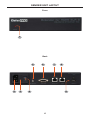
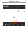
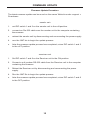
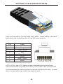
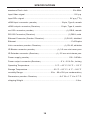
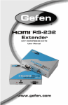
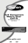
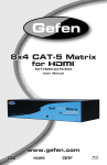
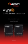
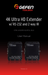
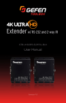
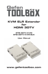
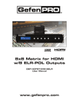
1080P
Extender for
HDMI ELR with POL
over CAT5
GEF-HDCAT5-ELRPOL
User Manual
www.gefenpro.com
®
ASKING FOR ASSISTANCE
Technical Support:
Telephone
Fax
(818) 772-9100
(800) 545-6900
(818) 772-9120
Technical Support Hours:
8:00 AM to 5:00 PM Monday thru Friday, Pacific Time
For 24 / 7 support, see the back of the product for the support number
Write To:
Gefen, LLC.
c/o Customer Service
20600 Nordhoff St
Chatsworth, CA 91311
www.gefenpro.com
[email protected]
Notice
Gefen, LLC reserves the right to make changes in the hardware, packaging, and
any accompanying documentation without prior written notice.
Extender for HDMI ELR with PoL over CAT5
is a trademark of Gefen, LLC
HDMI, the HDMI logo, and High-Definition Multimedia Interface are
trademarks or registered trademarks of HDMI Licensing in the United States and
other countries.
© 2012 Gefen, LLC. All rights reserved.
All trademarks are the property of their respective owners.
Rev A8
CONTENTS
1
Introduction
2
Operation Notes
3
Features
4
Sender Unit Layout
5
Sender Unit Descriptions
6
Receiver Unit Layout
7
Receiver Unit Descriptions
8
Connecting the Extender for HDMI ELR with PoL over CAT5
8
9
Wiring Diagram
DIP Switch Configuration
9
Sender Unit
11
Receiver Unit
15 Firmware Update
16 Network Cable Wiring Diagram
17 Troubleshooting
18 Specifications
19 Warranty
INTRODUCTION
Congratulations on your purchase of the Extender for HDMI ELR with PoL over
CAT5. Your complete satisfaction is very important to us.
GefenPRO
In the realm of video distribution, certain features are invaluable in a commercial
or broadcast environment. Accommodations such as a build-in power supply and
flat black rack-mount enclosures set GefenPRO apart from our traditional products. Complex distribution units allow for professional DVI, 3G-SDI, and HDMI
signals to be routed and converted easily and seamlessly, while being backed
up by a renowned and dependable technical support team. Gefen invites you to
explore the GefenPRO product line and hopes that you find the solution that fits
your needs.
The GefenPRO Extender for HDMI ELR with PoL over CAT5
The GefenPRO Extender for HDMI ELR with PoL (Power over Link) over CAT5
extends a Hi-Def source with multichannel digital audio at resolutions of up to
1080p Full HD to 330 feet (100 meters) using one CAT-5 cable. Also, it has the
capability to power a separate 5V DC device from the Receiver unit, sharing the
5V DC power, transmitted over the CAT-5 cable, up to 2.5 Amps at the Receiver
Unit. DVI-D is supported when used with an HDMI to DVI Adapter, providing
greater flexibility and options when integrating several home theater components.
This product also extends Ethernet and provides an IR back channel to control
AV sources using the same CAT-5 cable extension. 3D content is supported
when a 3DTV and a 3D source are connected to the Sender Unit. With the builtin IR Blaster, simply point the IR remote(s) at the display to control the Hi-Def
sources as if they were located in the same room as the display.
How It Works
The GefenPRO Extender for HDMI ELR with PoL over CAT5 Sender unit is
located next to a set-top box or DVD player source. Connect an HDMI source
with the supplied cables to the GefenPRO Extender for HDMI ELR with PoL over
CAT5 to the Sender Unit. The GefenPRO Extender for HDMI ELR with PoL over
CAT5 Receiver unit is located next to the display - up to 330 feet away from the
source. The HDTV display plugs into the back of the GefenPRO Extender for
HDMI ELR with PoL over CAT5 Receiver unit. One CAT-5 cable connects the
Sender and the Receiver units to each other. The Ethernet ports on both the
Sender and Receiver units are connected to standard network devices such as
Ethernet switches. Multichannel digital audio is embedded in the HDMI signal
(Dolby® TrueHD / DTS-HD Master Audio ™).
1
OPERATION NOTES
READ THESE NOTES BEFORE INSTALLING OR
OPERATING THE EXTENDER FOR HDMI ELR WITH POL OVER CAT5
•
The Extender for HDMI ELR with PoL over CAT5 units are housed in a metal
box for better RF shielding.
•
CAT-5 cables should not exceed 330 feet.
•
Shielded CAT-6 with metal RJ-45 connectors are recommended to safeguard
against random video flashes caused by electromagnetic interference (EMI).
•
The Extender for HDMI ELR with PoL over CAT5 features the ability
to generate compatible EDID and Hot Plug signals for troubleshooting
purposes when dealing with difficult interfacing issues between Source
devices and Displays. Refer to page 12 for details.
•
HDCP content is not supported when the unit is in DVI mode. See page 12
for details.
•
Ethernet works as a Full Duplex system.
2
FEATURES
HDMI Features
•
225 MHz (up to 12-bit YUV 444 @ 1080p)
•
Deep Color
•
x.v.Color
•
Dolby® TrueHD and DTS-HD Master Audio™
•
Lip-Sync
Features
•
Extends HDMI at 1080p Full HD and 1920x1200 up to 330 feet
•
Extends RS-232 up to 330 feet over a single CAT5
•
Supports high bit-rate audio formats (Dolby TrueHD and DTS-HD Master
Audio)
•
Supports 3DTV
•
Fully HDMI and HDCP compliant
•
EDID management for rapid integration of source and display devices
•
Built-in IR Blaster allows IR remote control of source devices from remote
viewing location
•
Internal 110 / 220 V AC Power Supply
•
5V DC, 2.5 A Locking Power Supply output connector on Receiver unit
•
Rack-mountable (with optional Gefen EXT-RACK-1U Rack Shelf)
•
Full-duplex Ethernet
Package Includes
(1)
(1)
(1)
(1)
(2)
(1)
Extender for HDMI ELR with PoL over CAT5 - Sender Unit
Extender for HDMI ELR with PoL over CAT5 - Receiver Unit
6 ft. HDMI locking cable (M-M)
AC power cord
Rack Ears
Quick-Start Guide
3
SENDER UNIT LAYOUT
Front
1
Back
5
2
3
6
7
4
8
9
4
SENDER UNIT DESCRIPTIONS
1
Power Indicator
This LED will glow bright red once power has been applied to the unit.
2
110 / 220 V AC Power Receptacle
Connect the included AC power cord to the power receptacle.
3
Fuse Drawer
Each power receptacle houses a fuse drawer. Within each fuse drawer are two
(2) 250 V fuses. One fuse is active and the other is a spare.
4
Power Switch
Turn the power ON or OFF using this switch.
5
IR Blaster Port
Connect an IR Blaster cable (Gefen part # EXT-2IREMIT) from this port to the
Hi-Def source to control the source from the viewing location.
6
RS-232 Serial Port
Connect an RS-232 control device to this port when extending RS-232. This
serial port is also used to update the Sender Unit firmware.
7
Ethernet Input Jack
Connects the Sender to the network using Ethernet cabling.
8
Link Jack
Connects the Sender to the Receiver unit using CAT-5 cabling.
9
Locking HDMI Port
Connect a Hi-Def source device to this HDMI port, using the included HDMI
cable.
5
RECEIVER UNIT LAYOUT
Front
1
2
Back
4
5
6
3
7
8
6
RECEIVER UNIT DESCRIPTIONS
1
IR Sensor
Receives signals from the Hi-Def source IR remote control. The IR signals are
sent back to the source device, when using an IR Blaster on the Sender.
2
Power Indicator
This LED will glow bright red once power has been applied to the unit.
3
5 V DC Locking Power Connector
Connect an optional locking (Gefen part no. CAB-PWR-06LL) or non-locking
(Gefen part no. CAB-PWR-06NL) to this power receptacle. This port supplies
5 V DC @ 2.5 A to power additional devices.
4
IR Extender Port
Connect an IR Extender (Gefen part no. EXT-RMT-EXTIR) cable from this port
to the Hi-Def source to extend the IR control.
5
RS-232 Serial Port
Used to extend RS-232. Connect the RS-232 controller to this port. This port is
also used to update the Receiver Unit firmware.
6
Ethernet Jack
Connects the Receiver Unit to the network device.
7
Link Jack
Connects the Receiver Unit to the Sender Unit using CAT-5 cabling.
8
Locking HDMI Port
Connect a Hi-Def source device to this HDMI port.
7
CONNECTING THE EXTENDER
FOR HDMI ELR WITH POL OVER CAT5
1.
Connect the Hi-Def source to the Sender Unit using the included HDMI cable.
2.
Use an HDMI cable to connect the HDTV display to the Receiver Unit.
3.
Connect the Ethernet device/router to the Ethernet input port on the Sender
unit using a CAT-5, CAT-5e or CAT-6 cable. Connect the Ethernet output port
on the Receiver Unit to the remote device/router with a CAT-5, CAT-5e or
CAT-6 cable.
4.
Use a CAT-5 or CAT-6 cable up to 330 ft (100 meters) to connect the Link
ports on both the Sender Unit and Receiver Unit.
NOTE: If terminating network cables in the field, please adhere to the
TIA/EIA568B specification. See page 16 for details.
5.
Connect the included AC power cord to the Sender Unit Plug the power
cord into an available electrical outlet.
NOTE: Connect an optional power cable (CAB-PWR-06LL or CAB-PWR06NL) to the Receiver Unit. The Receiver Unit supplies 5 V DC (@ 2A) to
power an additional device.
6.
Power on the HDTV display and the Hi-Def source.
CAT-5 LINK CABLE
(Up to 330 ft)
ETHERNET CABLE
RS-232 CABLE
HDMI CABLE
Set Top Box
5 V DC POWER
100BASE-T
Router
Sender
RS-232 Controller
Receiver
Digital Signage Creator
(or other Gefen device)
HD Display
GEF-HDCAT5-ELRPOL
WARNING: This product should always be connected to a
grounded electrical socket.
8
DIP SWITCH CONFIGURATION
Sender Unit
The GefenPRO Extender for HDMI ELR with PoL over CAT5 contains two DIP
switches on the bottom of the Sender Unit. Each DIP switch performs a different
function.
•
•
DIP switches located on the
bottom of the Sender Unit.
•
•
DIP Switch 1 - Green Mode (Default = OFF)
•
OFF
F - Enable Green Mode
When DIP switch 1 on the Sender Unt is set to the OFF position, the Sender
Unit is placed in Green Mode. In this mode, the unit is not powered unless
+5V is detected on pin 18 of the HDMI cable. Green Mode consumes less
than 1 Watt of power.
•
ON
N - Disable Green Mode
If DIP switch 1 is set to the ON position, then the Sender Unit is always
powered.
NOTE: Both the Sender Unit and Receiver Unit must be placed in
Green Mode in order to use the Green Mode feature
9
DIP SWITCH CONFIGURATION
Sender Unit
DIP Switch 2 - Field-Upgrade Mode (Default = OFF)
•
ON - Enable Field Upgrade Mode (VALENS chip)
Allows the firmware to be upgraded on the Receiver unit. If DIP switch 6
and/or 7 are in the ON position, RS-232 cannot be extended. See page 15
for details on upgrading the firmware.
•
OFF - RS-232 Pass-Through
Use when extending RS-232 between the Sender unit and the Receiver unit.
DIP switch 6 and 7 must be set to the OFF position for normal operation of
the Extender for HDMI ELR with PoL over CAT5.
10
DIP SWITCH CONFIGURATION
Receiver Unit
The GefenPRO Extender for HDMI ELR with PoL over CAT5 contains eight DIP
switches on the bottom of the Receiver Unit. Each of these DIP switch performs
a different function.
DIP switches located on the
bottom of the Receiver Unit.
See the next page for a description of the DIP switches.
11
DIP SWITCH CONFIGURATION
Receiver Unit
DIP Switch 1 - EDID Mode (Default = OFF)
•
ON
N - Pass-Through Mode
DDC and HPD are passed through. Both the connection status and the full
video capabilities of the monitor are used by the source device.
•
OFF
F - Local EDID Mode
Local EDID is used instead of the EDID from the display device. EDID
features newer than HDMI 1.3 are removed when the display is read. This
provides a general EDID which is compatible with more displays.
DIP Switch 2 - Hot Plug Detect (Default = OFF)
•
ON
N - HPD Pass-Through
HPD follows upstream HPD towards the source. The HPD signal will reflect
the connection status between the display device and the source device. If
the source or monitor is temporarily disconnected then reconnected, there
will be a delay of 20 - 30 seconds before the content is restored to the
monitor.
•
OFF
F - HPD Always High
The HPD signal remains high regardless of the downstream HPD state.
If the source or monitor does not properly handle HPD (no picture after
connecting / reconnecting source or display), set this DIP switch to the OFF
position.
DIP Switch 3 - Support DVI Connections (Default = OFF)
•
ON
N - Disable HDCP
If a DVI connection is used, set DIP 3 to the ON position. DVI is supported
by disabling HDCP pass-through.
•
OFF
F - Enable HDCP
If an HDMI device is connected, set DIP 3 in the OFF position.
NOTE: DIP switch 2 (HPD) and 3 (HDCP) are operational only if DIP
switch 1 (EDID mode) is set to the OFF position.
12
DIP SWITCH CONFIGURATION
Receiver Unit
DIP Switch 4 - Not Used
•
Reserved for future expansion.
DIP Switch 5 - Not Used
•
Reserved for future expansion.
DIP Switch 6 - Field-upgrade Mode (Default = OFF)
•
ON - Enable Field Upgrade Mode (Cortex chip)
Allows the firmware to be upgraded on the Receiver unit. If DIP switch 6
and/or 7 are in the ON position, RS-232 cannot be extended. See page 15
for details on upgrading the firmware.
•
OFF - RS-232 Pass-Through
Use when extending RS-232 between the Sender unit and the Receiver unit.
DIP switch 6 and 7 must be set to the OFF position for normal operation of
the Extender for HDMI ELR with PoL over CAT5.
DIP Switch 7 - Field-Upgrade Mode (Default = OFF)
•
ON - Enable Field Upgrade Mode (VALENS chip)
Allows the firmware to be upgraded on the Receiver unit. If DIP switch 6
and/or 7 are in the ON position, RS-232 cannot be extended. See page 15
for details on upgrading the firmware.
•
OFF - RS-232 Pass-Through
Use when extending RS-232 between the Sender unit and the Receiver unit.
DIP switch 6 and 7 must be set to the OFF position for normal operation of
the Extender for HDMI ELR with PoL over CAT5.
13
DIP SWITCH CONFIGURATION
Receiver Unit
DIP Switch 8 - Green Mode (Default = OFF)
•
OFF
F - Enable Green Mode
When DIP switch 1 on the Receiver Unt is set to the OFF position, the
Receiver Unit is placed in Green Mode. In this mode, the unit is not powered
unless +5V is detected on pin 18 of the HDMI cable. Green Mode consumes
less than 1 Watt of power.
•
ON
N - Disable Green Mode
If DIP switch 1 is set to the ON position, then the Receiver Unit is always
powered.
NOTE: Both the Sender Unit and Receiver Unit must be placed in
Green Mode in order to use the Green Mode feature
14
FIRMWARE UPDATE
Firmware Update Procedure
The latest firmware update can be found on the Gefen Web site under Support >
Downloads.
Sender Unit
1.
Set DIP switch 1 and 2 on the Sender unit to the ON position.
2.
Connect an RS-232 cable from the Sender unit to the computer containing
the firmware.
3.
Reboot the Sender unit by disconnecting and reconnecting the power supply.
4.
Run the .BAT file to begin the update process.
5.
After the firmware update process has completed, return DIP switch 1 and 2
to the OFF position.
Receiver Unit
1.
Set DIP switch 7 and 8 on the Receiver unit to the ON position.
2.
Connect a null modem RS-232 cable from the Receiver unit to the computer
containing the firmware.
3.
Reboot the Receiver unit by disconnecting and reconnecting the power
supply.
4.
Run the .BAT file to begin the update process.
5.
After the firmware update process has completed, return DIP switch 7 and 8
to the OFF position.
15
NETWORK CABLE WIRING DIAGRAM
Gefen recommends the TIA/EIA-568-B wiring option. Please adhere to the table
below when field terminating cable for use with Gefen products.
Pin
Color
1
Orange / White
2
Orange
3
Green / White
4
Blue
5
Blue / White
6
Green
7
Brown / White
8
Brown
12345678
CAT-5, CAT-5e, and CAT-6 cabling comes in stranded and solid core types.
Gefen recommends using solid core cabling. CAT-6 cable is also recommended.
It is recommended to use one continuous run from one end to the other. In some
cases, connecting through a patch bay might not work.
16
TROUBLESHOOTING
Cable recommendations
Solid core CAT-5e cable rated at 350 MHz and terminated in 568a or 568b is the
minimum requirement. For resolutions greater than 1280x1024 or 1080i, Gefen
recommends solid shielded CAT-6 cables.
No video
Make sure that DIP switch 2 on the Sender Unit is set to the OFF position. Also
make sure that DIP switch 7 on the Receiver Unit is set to the OFF position. If
either of these DIP switches are in the ON position (Field-Upgrade Mode, see
page 10 and 13) then the Sender Unit or Receiver Unit will not function as an
extender. Next, make sure that the CAT-5 cable, connecting the Sender Unit and
Receiver Unit is connected to the LINK port. If this does not solve the issue, try
disconnecting and then reconnecting the AC power cord from the Sender Unit.
Also, verify that both units are working with short CAT-5e cables (15 - 20 feet).
Intermittent loss of video
Flickering or a blinking image is the result of a loss of sync between the display
and the source. Try lowering the source resolution (e.g. from 1080p to 720p). If
this solves the issue, then the CAT-5 cables being used to connect the Sender
Unit and the Receiver Unit are unable to handle the bandwidth of the higher
resolution and thus you are losing sync. Replace the existing CAT-5 cables with
a shielded CAT-6 cable. Electromagnetic Interference (EMI) from fluorescent
lights, generators, and A/C unit motors can also cause intermittent loss of video.
Shielded CAT-6 cable with the drain wire soldered to the connectors will resolve
the issue. Also make sure to eliminate any patch panels and wall plates. Patch
panels and wall plates are prone to EMI if they are not shielded properly.
Image is tinted green or pink
An image that is tinted green or pink is the result of the incorrect color space
being transmitted. Make sure that the display and source both support the same
color space. Setting DIP switch 1 on the Receiver Unit, to the OFF position, will
use the Local EDID. EDID features newer than HDMI 1.3 are removed when
the display is read. This provides a general EDID which is compatible with more
displays.
17
SPECIFICATIONS
Maximum Pixel Clock .............................................................................. 225 MHz
Input Video Signal .................................................................................... 1.2V p-p
Input DDC Signal ............................................................................... 5V p-p (TTL)
HDMI Input Connector (Sender) ......................................... 19-pin, Type A, female
HDMI Output Connector (Receiver) ................................... 19-pin, Type A, female
RS-232 Connector (Sender) ........................................................ (1) DB-9, female
RS-232 Connector (Receiver) ........................................................ (1) DB-9, male
Ethernet Connector (Sender / Receiver) ................................. (1) RJ-45, shielded
Ethernet ................................................................................................ Full Duplex
Link Connectors (Sender / Receiver) ....................................... (1) RJ-45, shielded
IR Blaster connector (Sender) ..................................... (1) 3.5 mm mini-mono jack
IR Extender connector (Receiver) .............................. (1) 3.5 mm mini-stereo jack
Power Supply (Sender) .................................................................... 100 - 240VAC
Power Output Connector (Receiver) ...................................5 V / 2.5 A DC, locking
Operating Temperature............................................. 0 °C ~ 45 °C / 32 °F ~ 113 °F
Storage Temperature............................................. -20 °C ~ 60 °C / -4 °F ~ 140 °F
Humidity Range................................................. 20% - 90% RH (no condensation)
Dimensions (Sender / Receiver) ...................................... 8.4” W x 1.7” H x 6.7” D
Shipping Weight ............................................................................................ 8 lbs.
18
WARRANTY
Gefen warrants the equipment it manufactures to be free from defects in material
and workmanship.
If equipment fails because of such defects and Gefen is notified within two (2)
years from the date of shipment, Gefen will, at its option, repair or replace the
equipment, provided that the equipment has not been subjected to mechanical,
electrical, or other abuse or modifications. Equipment that fails under conditions
other than those covered will be repaired at the current price of parts and labor in
effect at the time of repair. Such repairs are warranted for ninety (90) days from
the day of reshipment to the Buyer.
This warranty is in lieu of all other warranties expressed or implied, including
without limitation, any implied warranty or merchantability or fitness for any
particular purpose, all of which are expressly disclaimed.
1.
Proof of sale may be required in order to claim warranty.
2.
Customers outside the US are responsible for shipping charges to and from
Gefen.
3.
Copper cables are limited to a 30 day warranty and cables must be in their
original condition.
The information in this manual has been carefully checked and is believed to
be accurate. However, Gefen assumes no responsibility for any inaccuracies
that may be contained in this manual. In no event will Gefen be liable for
direct, indirect, special, incidental, or consequential damages resulting from
any defect or omission in this manual, even if advised of the possibility of such
damages. The technical information contained herein regarding the features and
specifications is subject to change without notice.
For the latest warranty coverage information, refer to the Warranty and Return
Policy under the Support section of the Gefen Web site at www.gefen.com.
PRODUCT REGISTRATION
Please register your product online by visiting the Register Product page
under the Support section of the Gefen Web site.
19
Rev A8
20600 Nordhoff St., Chatsworth CA 91311
1-800-545-6900
818-772-9100
www.gefenpro.com
Pb
fax: 818-772-9120
[email protected]