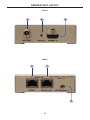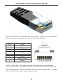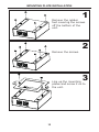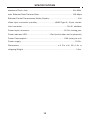
1
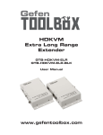
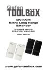
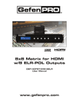
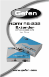
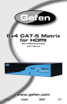
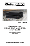
®
Extender for
HDMI 1.3 over CAT5
with Ethernet
EXT-HDMI1.3-CAT5-ELR
User Manual
®
1080P
www.gefen.com
ASKING FOR ASSISTANCE
Technical Support:
Telephone
Fax
(818) 772-9100
(800) 545-6900
(818) 772-9120
Technical Support Hours:
8:00 AM to 5:00 PM Monday thru Friday, Pacific Time
Write To:
Gefen, LLC.
c/o Customer Service
20600 Nordhoff St
Chatsworth, CA 91311
www.gefen.com
[email protected]
Notice
Gefen, LLC reserves the right to make changes in the hardware, packaging and
any accompanying documentation without prior written notice.
Extender for HDMI 1.3 over CAT5 with Ethernet
is a trademark of Gefen, LLC
HDMI, the HDMI logo, and High-Definition Multimedia Interface are
trademarks or registered trademarks of HDMI Licensing in the United States and
other countries.
© 2011 Gefen, LLC. All rights reserved.
All trademarks are the property of their respective owners.
Rev A13
CONTENTS
1
Introduction
2
Operation Notes
3
Features
4
Sender Unit Layout
5
Sender Panel Descriptions
6
Receiver Panel Layout
7
Receiver Panel Descriptions
8
Connecting the Extender for HDMI 1.3 over CAT-5 with Ethernet
8
Wiring Diagram
9
Network Cable Wiring Diagram
10
DIP Switches
11
DIP Switch Settings
12 Mounting Plate Installation
13 Terminology
14 Specifications
15 Warranty
INTRODUCTION
Congratulations on your purchase of the Extender for HDMI 1.3 over CAT5 with
Ethernet. Your complete satisfaction is very important to us.
Gefen
Gefen delivers innovative, progressive computer and electronics add-on solutions
that harness integration, extension, distribution and conversion technologies.
Gefen’s reliable, plug-and-play products supplement cross-platform computer
systems, professional audio/video environments and HDTV systems of all sizes
with hard-working solutions that are easy to implement and simple to operate.
The Gefen Extender for HDMI 1.3 over CAT5 with Ethernet
The Extender for HDMI 1.3 over CAT5 with Ethernet extends a Hi-Def Display with
multi-channel digital audio and Ethernet at resolutions of 1080p Full HD and 4K
(4096 x 2160 @ 24 Hz) t up to 330 feet (100 meters) using one CAT-5 cable.
DVI-D is supported when used with an HDMI to DVI Adapter, providing greater
flexibility and options when integrating several home theater components. 3D
content can be displayed when a 3DTV and 3D source are connected.
Extension of Ethernet connectivity enables internet or local area network access
for HDTVs, home PCs, video game consoles, DVRs and any device that needs
fast 10/100Base-T network access, at convenient locations.
The IR back-channel feature lets users control Hi-Def Sources as if they were
located at the Display. IR commands are processed by the IR eye on the receiver,
transmitted back over the CAT5 extension, and then sent to original A/V Source
devices located by the sender unit using the IR Blaster (sold separately).
How It Works
Connect the Gefen Extender for HDMI 1.3 over CAT5 with Ethernet sender
unit to the A/V and Ethernet Source devices such as infrastructure, routers and
switches using short HDMI and CAT5 cables. Do the same operation between
the Extender receiver and the extended HD Display and any network devices that
you are connecting to. When the Extender sender and receiver units have been
connected to Sources, Displays and network equipment, connect a single CAT5
extension cable between sender and receiver. The Extender sender and receiver
units may be up to 330 feet apart.
Note: The Extender for HDMI 1.3 over CAT5 with Ethernet is fully HDMI and
HDCP compliant.
1
OPERATION NOTES
READ THESE NOTES BEFORE INSTALLING OR
OPERATING THE EXTENDER FOR HDMI 1.3 OVER CAT5 WITH ETHERNET
•
The Extender for HDMI 1.3 over CAT5 with Ethernet units are housed in a
metal box for better RF shielding.
•
CAT-5 cables should not exceed 330 feet.
•
Shielded CAT-6 with metal RJ-45 connectors are recommended to safeguard
against random video flashes caused by electromagnetic interference (EMI).
•
The Extender for HDMI 1.3 over CAT5 with Ethernet features the ability
to generate compatible EDID and Hot Plug signals for troubleshooting
purposes when dealing with difficult interfacing issues between Source
devices and Displays. Refer to pages 9 and 10 for details.
•
HDCP content is not supported when the unit is in DVI mode. See page 10
for details.
2
FEATURES
HDMI 1.3 Features
•
225 MHz (up to 12-bit YUV 444 @ 1080p)
•
Deep Color
•
Dolby TrueHD and DTS-HD Master Audio
•
Lip-Sync
•
CEC Pass-Through
Features
•
Extends HDMI1.3 at 1080p60 over Ethernet up to 330 feet along with
Ethernet and IR commands
•
Built-in IR extender function allows IR remote control of Source devices from
remote viewing location by sending IR commands received in the vicinity of
the Display back to the Source devices
•
3DTV Pass-Through
•
Supports high bit-rate multi-channel audio formats (Dolby TrueHD / DTS
Master Audio) embedded in the HDMI 1.3 signal
•
Fully HDMI and HDCP compliant
•
Extends Ethernet protocol from a network switch to a device up to 330 feet
away
•
Locking power connectors on the Extender units and power supplies for
secure connections
•
Eliminates equipment noise in the viewing environment
•
All-digital signal transmission over the CAT-5 cable for zero signal loss
•
Built-in auto video signal equalization
•
EDID and Hot Plug signal generation features for troubleshooting difficult
Source-Display interfacing issues.
Package Includes
(1)
(1)
(1)
(2)
(2)
(1)
Extender for HDMI 1.3 over CAT5 with Ethernet - Sender
Extender for HDMI 1.3 over CAT5 with Ethernet - Receiver
6 ft. HDMI locking cable (M-M)
Mounting Plates
5V DC Locking Power Supply
Quick Start Guide
3
SENDER UNIT LAYOUT
Front
1
2
3
Back
4
5
6
4
SENDER UNIT DESCRIPTIONS
1
5V DC
Connect the included 5V DC locking power supply to this connector. Only use
the power supply shipped with this unit.
2
Power
This LED will glow bright red once the included 5V DC locking power supply
has been properly connected to the unit and the locking power supply has been
connected to an available wall outlet.
3
HDMI In
Connect an HDMI cable from this port to the Hi-Def source.
4
Link
Connects the Sender unit to the Receiver unit using CAT-5 cabling.
5
Ethernet
Connects the Sender to the network using Ethernet cabling.
6
IR Blaster
Connect an IR Blaster cable (Gefen part # EXT-2IREMIT) from this port to the
Hi-Def source to control the source from the viewing location.
5
RECEIVER UNIT LAYOUT
Front
1
3
4
2
Back
6
7
5
6
RECEIVER UNIT DESCRIPTIONS
1
IR
This IR sensor receives signals from the Hi-Def source IR remote control. The
IR signals are sent back to the source device, when using an IR Blaster on the
Sender.
2
HDMI Out
Connect a locking HDMI cable from this port to an HDTV display.
3
Power
This LED will glow bright red once the included 5V DC locking power supply
has been properly connected to the unit and the locking power supply has been
connected to an available wall outlet.
4
5V DC
Connect the included 5V DC locking power supply to this connector. Only use
the power supply shipped with this unit.
5
Ext IR
Connect an IR Extender (Gefen part no. EXT-RMT-EXTIR) cable from this port
to the Hi-Def source to extend the IR control.
6
Ethernet
Connects the receiver unit to the network device.
7
Link
Connects the Receiver unit to the Sender unit using CAT-5 cabling.
7
CONNECTING THE EXTENDER FOR
HDMI 1.3 OVER CAT5 WITH ETHERNET
1.
Connect the Hi-Def source to the Sender Unit using the included HDMI cable.
2.
Use an HDMI cable to connect the HDTV display to the Receiver Unit.
3.
Connect the Ethernet device/router to the Ethernet input port on the Sender
unit using a CAT-5, CAT-5e or CAT-6 cable. Connect the Ethernet output port
on the Receiver Unit to the remote device/router with a CAT-5, CAT-5e or
CAT-6 cable.
4.
Use a CAT-5 or CAT-6 cable up to 330 feet (100 meters) to connect the
Sender Unit and Receiver Unit.
NOTE: If terminating network cables in the field, please adhere to
the TIA/EIA568B specification (see page 11).
5.
Connect the included 5V DC Locking Power Supplies to the Sender Unit
and Receiver Unit. Do not overtighten the locking connectors. Plug the
two power supplies into an available electrical outlet using the included AC
power cords. The Sender and Receiver units will now power up.
NOTE: If the power LED indicator on the receiver unit is not on,
check to make sure that the CAT5 cables are not crossed (Ethernet
to Link instead of Ethernet to Ethernet, for instance).
Wiring Diagram for the Extender for HDMI 1.3 over CAT5 with Ethernet
CAT5 CABLE
HDMI CABLE
IR
ETHERNET
Ethernet
Source
Hi-Def
Source
(Up to 300 ft)
IR Extender
IR Emitter
Receiver
Sender
HD Display
with Ethernet
EXT-HDMI1.3-CAT5-ELR
8
DIP SWITCHES
DIP Switch Location
On the bottom of the Extender for HDMI 1.3 with Ethernet Receiver unit there are
four (4) DIP switches.
The DIP switches allow advanced EDID management of the Extender for HDMI
1.3 with Ethernet which may be necessary when troubleshooting or using
different brands of hardware. The DIP switches allow control over the EDID and
the HPD (Hot Plug Detect) status.
Rece
eiver Unit (bottom)
Default settings for DIP switches
DIP Switch
Position
1
ON
2
OFF
3
OFF
4
NOT USED
9
DIP SWITCH SETTINGS
DIP 1 - EDID Mode
ON (default) - External EDID Mode
•
DDC and HPD are passed through. Both the connection status and the full
A/V capabilities of the display. The HPD status will also be detected by the
source device.
OFF - Internal EDID Mode
•
Local EDID is used instead of the EDID from the display device. EDID
features newer than HDMI 1.3 are removed when the display is read. This
provides a general EDID which is compatible with more displays.
DIP 2 - Hot-Plug Detect
DIP switch 2 only works when DIP switch 1 is set to the OFF position.
ON - HPD Pass-Through
•
HPD follows upstream HPD towards the source. The HPD signal will reflect
the connection status between the display device and the source device. If
the source or display is temporarily disconnected then reconnected, there
will be a delay of 20 - 30 seconds before the A/V content is restored to the
display.
OFF (default) - HPD Always High
•
The HPD signal remains high regardless of the downstream HPD state. If
the source or display device does not properly handle HPD (no picture after
connecting / reconnecting source or display), set this DIP switch to the OFF
position.
DIP 3 - Supports DVI Connections
DIP switch 3 only works when DIP switch 1 is set to the OFF position.
ON
•
Set DIP switch 3 to the ON position when using a DVI source or display.
HDCP content is nott supported in this mode.
OFF (default)
•
If HDMI is connected, set DIP 3 in the OFF position.
10
NETWORK CABLE WIRING DIAGRAM
Gefen recommends the TIA/EIA-568-B wiring option. Please adhere to the table
below when field terminating cable for use with Gefen products.
Pin
Color
1
Orange / White
2
Orange
3
Green / White
4
Blue
5
Blue / White
6
Green
7
Brown / White
8
Brown
12345678
CAT-5, CAT-5e, and CAT-6 cabling comes in stranded and solid core types.
Gefen recommends using solid core cabling. CAT-6 cable is also recommended.
It is recommended to use one continuous run from one end to the other. In some
cases, connecting through a patch might not work.
11
MOUNTING PLATE INSTALLATION
1
Remove the rubber
feet covering the screws
off the bottom of the
unit.
Remove the screws.
2
3
Line up the mounting
plates and screw it on to
the unit.
12
TERMINOLOGY
CAT-5/CAT5e
Category 5 cable, commonly known as Cat 5, is an unshielded twisted pair type
cable designed for high signal integrity. The actual standard defines specific electrical
properties of the wire, but it is mostly known as being rated for its Ethernet capability of
100 Mbit/s. Its specific standard designation is EIA/TIA-568. Cat 5 cable typically has 3
twists per inch of each twisted pair of 24 gauge copper wires within the cable. CAT-5e
is similar to Cat 5 cable, but is enhanced to support speeds of up to 1000 Megabits/sec.
DDWG
Digital Display Working Group DDWG are the creators of the DVI specification.
DVI
Digital Visual Interface. A digital video standard established by DDWG, designed to
carry uncompressed digital video signals to a Display.
HDMI
The High-Definition Multi-media Interface (HDMI) is an industry-supported,
uncompressed, all-digital audio/video interface. HDMI provides an interface between
any compatible digital audio/video Source, such as a set-top box, DVD player, and
A/V receiver and a compatible digital audio and/or video monitor, such as a digital
television (DTV).
HDCP
High-Bandwidth Digital Content Protection. Created by Intel, HDCP is used with HDTV
signals over HDMI and HDMI connections and on D-Theater D-VHS recordings to
prevent unauthorized duplication of copy written material.
HDTV
High-Definition Television. The high-resolution subset of our DTV system. The ATSC
defines HDTV as a 16:9 image with twice the horizontal and vertical resolution of our
existing system, accompanied by 5.1 channels of Dolby Digital audio. The CEA defines
HDTV as an image with 720 progressive or 1080 interlaced active (top to bottom) scan
lines. 1280:720p and 1920:1080i are typically accepted as high-def scan rates.
HPD
Hot Plug Detect. HPD is an electronic status signal which is used to signal the presence
of absence of a Display device on the output of a digital audio/video interface, usually
an A/V media player, scaler, splitter, etc.
EDID
Electronic Data Information Display. EDID is an electronic ID containing the capabilities
of an audio/video output device such as an HDTV. Source devices will read the EDID
of a Display or output device in order to know what resolution(s) should be used to
draw a picture and how many channels to use when playing audio.
DDC
Display Data Channel. Provides information which allows rendering of a video picture.
11
SPECIFICATIONS
Maximum Pixel Clock .............................................................................. 225 MHz
Max. Ethernet Data Transfer Rate........................................................... 100 Mbps
Ethernet Packet Transmission Mode (Duplex): .................................................Full
Video Input Connector (Sender)............................... HDMI Type-A, 19-pin, female
Link Connector .............................................................................. RJ-45, shielded
Power Input Connector : ...........................................................5V DC locking jack
Power indicator LED: ........................................Red (active when unit is powered)
Power Consumption ................................................................ 10W (max) per unit
Power Supply .............................................................................................. 5V DC
Dimensions ................................................................... 3.4” D x 3.25” W x 1.25” H
Shipping Weight ............................................................................................ 3 lbs.
12
WARRANTY
Gefen warrants the equipment it manufactures to be free from defects in material
and workmanship.
If equipment fails because of such defects and Gefen is notified within two (2)
years from the date of shipment, Gefen will, at its option, repair or replace the
equipment, provided that the equipment has not been subjected to mechanical,
electrical, or other abuse or modifications. Equipment that fails under conditions
other than those covered will be repaired at the current price of parts and labor in
effect at the time of repair. Such repairs are warranted for ninety (90) days from
the day of reshipment to the Buyer.
This warranty is in lieu of all other warranties expressed or implied, including
without limitation, any implied warranty or merchantability or fitness for any
particular purpose, all of which are expressly disclaimed.
1.
Proof of sale may be required in order to claim warranty.
2.
Customers outside the US are responsible for shipping charges to and from
Gefen.
3.
Copper cables are limited to a 30 day warranty and cables must be in their
original condition.
The information in this manual has been carefully checked and is believed to
be accurate. However, Gefen assumes no responsibility for any inaccuracies
that may be contained in this manual. In no event will Gefen be liable for
direct, indirect, special, incidental, or consequential damages resulting from
any defect or omission in this manual, even if advised of the possibility of such
damages. The technical information contained herein regarding the features and
specifications is subject to change without notice.
For the latest warranty coverage information, refer to the Warranty and Return
Policy under the Support section of the Gefen Web site at www.gefen.com.
PRODUCT REGISTRATION
Please register your product online by visiting the Register Product page
under the Support section of the Gefen Web site.
13
Rev A13
20600 Nordhoff St., Chatsworth CA 91311
1-800-545-6900
818-772-9100
www.gefen.com
Pb
This product uses UL or CE listed power supplies.
fax: 818-772-9120
[email protected]