1
Operation/Reference Guide
®
Mio Modero R-4
ZigBee Pro Remote Control
M i o R e m o t e C on t r ol s
Last updated: 1/13/2012
AMX Limited Warranty and Disclaimer
AMX warrants its products to be free of defects in material and workmanship under normal use for three (3) years from
the date of purchase from AMX, with the following exceptions:
•
Electroluminescent and LCD Control Panels are warranted for three (3) years, except for the display and touch
overlay components that are warranted for a period of one (1) year.
•
Disk drive mechanisms, pan/tilt heads, power supplies, and MX Series products are warranted for a period of one
(1) year.
•
AMX Lighting products are guaranteed to switch on and off any load that is properly connected to our lighting
products, as long as the AMX Lighting products are under warranty. AMX does guarantee the control of dimmable
loads that are properly connected to our lighting products. The dimming performance or quality cannot be
guaranteed due to the random combinations of dimmers, lamps and ballasts or transformers.
•
Unless otherwise specified, OEM and custom products are warranted for a period of one (1) year.
•
AMX Software is warranted for a period of ninety (90) days.
•
Batteries and incandescent lamps are not covered under the warranty.
This warranty extends only to products purchased directly from AMX or an Authorized AMX Dealer.
All products returned to AMX require a Return Material Authorization (RMA) number. The RMA number is obtained
from the AMX RMA Department. The RMA number must be clearly marked on the outside of each box. The RMA is
valid for a 30-day period. After the 30-day period the RMA will be cancelled. Any shipments received not consistent
with the RMA, or after the RMA is cancelled, will be refused. AMX is not responsible for products returned without a
valid RMA number.
AMX is not liable for any damages caused by its products or for the failure of its products to perform. This includes any
lost profits, lost savings, incidental damages, or consequential damages. AMX is not liable for any claim made by a
third party or by an AMX Dealer for a third party.
This limitation of liability applies whether damages are sought, or a claim is made, under this warranty or as a tort claim
(including negligence and strict product liability), a contract claim, or any other claim. This limitation of liability cannot
be waived or amended by any person. This limitation of liability will be effective even if AMX or an authorized
representative of AMX has been advised of the possibility of any such damages. This limitation of liability, however, will
not apply to claims for personal injury.
Some states do not allow a limitation of how long an implied warranty last. Some states do not allow the limitation or
exclusion of incidental or consequential damages for consumer products. In such states, the limitation or exclusion of
the Limited Warranty may not apply. This Limited Warranty gives the owner specific legal rights. The owner may also
have other rights that vary from state to state. The owner is advised to consult applicable state laws for full
determination of rights.
EXCEPT AS EXPRESSLY SET FORTH IN THIS WARRANTY, AMX MAKES NO OTHER WARRANTIES,
EXPRESSED OR IMPLIED, INCLUDING ANY IMPLIED WARRANTIES OF MERCHANTABILITY OR FITNESS FOR
A PARTICULAR PURPOSE. AMX EXPRESSLY DISCLAIMS ALL WARRANTIES NOT STATED IN THIS LIMITED
WARRANTY. ANY IMPLIED WARRANTIES THAT MAY BE IMPOSED BY LAW ARE LIMITED TO THE TERMS OF
THIS LIMITED WARRANTY.
Table of Contents
Table of Contents
Mio Modero® R-4 Remote .................................................................................1
Overview .................................................................................................................. 1
Touch And Tilt Sensor ..................................................................................................... 2
Specifications............................................................................................................ 2
Display Features ....................................................................................................... 3
Device Navigation..................................................................................................... 3
FCC Compliance ....................................................................................................... 4
Patents...................................................................................................................... 4
Mio R-4 Setup .....................................................................................................5
Installing or Replacing the Mio R-4 Lithium-Ion Battery............................................ 5
Battery Low Indicator ............................................................................................... 6
Customized Keypads ..........................................................................................7
Installing Keypads..................................................................................................... 7
Device Setup Pages ............................................................................................9
Overview .................................................................................................................. 9
Accessing the Setup Pages ............................................................................................. 9
Project Information ................................................................................................. 10
Viewing Project Information.......................................................................................... 10
Remote & Display Settings ..................................................................................... 11
Changing the remote and display settings.................................................................... 12
Raising and lowering the LCD brightness...................................................................... 13
Raising and lowering the charge LED brightness .......................................................... 13
Setting the Home Hold Time......................................................................................... 13
Changing the remote inactivity page flip ...................................................................... 14
Checking remote display settings ................................................................................. 14
Date/Time Settings ................................................................................................. 15
Getting time and date from your NetLinx Master......................................................... 15
Sound Settings........................................................................................................ 16
Setting the volume........................................................................................................ 16
Testing the sound settings ............................................................................................ 16
Battery Settings ...................................................................................................... 17
Checking Dock Status ................................................................................................... 17
Toggling Brightness Limit ............................................................................................. 17
Protected Settings Menu ..................................................................................19
Overview ................................................................................................................ 19
Password Entry ....................................................................................................... 20
Mio R-4
i
Table of Contents
Entering a numeric password ........................................................................................ 20
Options & Recovery Page ....................................................................................... 21
Checking the device number......................................................................................... 21
Toggling the Function Show option .............................................................................. 21
Toggling the Page Tracking option ............................................................................... 22
Resetting System Settings............................................................................................. 22
Removing User Pages.................................................................................................... 22
Enabling Front Button Setup Access ............................................................................. 23
Edit Passwords........................................................................................................ 23
Changing the device password ..................................................................................... 23
Calibrate ................................................................................................................. 24
Calibrating the touch screen area ................................................................................. 24
System Settings ...................................................................................................... 25
Checking connection status........................................................................................... 25
Checking the master IP address .................................................................................... 25
Checking the gateway IP address.................................................................................. 26
Checking the Gateway EUI address............................................................................... 26
Checking the Extended PAN ID .................................................................................... 26
Changing the Device Number ....................................................................................... 26
Site Survey .............................................................................................................. 27
Joining a wireless network ............................................................................................ 27
ZigBee Diagnostics ................................................................................................. 28
Reboot Page ........................................................................................................... 29
Rebooting the device .................................................................................................... 29
Test Pages .............................................................................................................. 29
Programming the Mio R-4 ................................................................................31
Overview ................................................................................................................ 31
Using the Programming Jack on the Mio R-4.......................................................... 31
Downloading Configuration Files through TPDesign4................................................... 32
Updating Firmware ................................................................................................. 32
Updating Mio R-4 Firmware Through USB .................................................................... 32
USB ......................................................................................................................... 33
Prepare your PC for USB communication with the Mio R-4........................................... 33
Configure a Virtual NetLinx Master using NetLinx Studio ............................................. 33
Programming Numbers........................................................................................... 35
Fixed Fonts and ID numbers.......................................................................................... 37
Slider/Cursor Names ..................................................................................................... 38
Border Styles by Numbers ............................................................................................ 38
Text Effects Names ................................................................................................. 40
ii
Mio R-4
Table of Contents
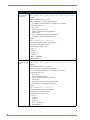
SEND_COMMANDs ................................................................................................ 41
Page Commands ........................................................................................................... 41
PAGE............................................................................................................................. 41
@APG ............................................................................................................................ 41
@CPG ............................................................................................................................ 41
@DPG ............................................................................................................................ 42
@PDR ............................................................................................................................ 42
@PHE............................................................................................................................. 42
@PHP............................................................................................................................. 42
@PHT............................................................................................................................. 43
@PPA............................................................................................................................. 43
@PPF ............................................................................................................................. 43
@PPG ............................................................................................................................ 43
@PPK............................................................................................................................. 44
@PPM ............................................................................................................................ 44
@PPN ............................................................................................................................ 44
@PPT ............................................................................................................................. 45
@PPX............................................................................................................................. 45
@PSE ............................................................................................................................. 45
@PSP ............................................................................................................................. 45
@PST ............................................................................................................................. 45
PPOF ............................................................................................................................. 46
PPOG ............................................................................................................................ 46
PPON ............................................................................................................................ 46
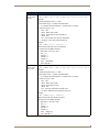
“^” Button Commands with Embedded Codes............................................................. 47
^BMF ............................................................................................................................ 47
“^” Button Commands.................................................................................................. 49
^ANI.............................................................................................................................. 49
^APF ............................................................................................................................. 49
^BAT ............................................................................................................................. 50
^BAU............................................................................................................................. 50
^BCB ............................................................................................................................. 50
^BCF ............................................................................................................................. 51
^BCT ............................................................................................................................. 51
^BDO ............................................................................................................................ 52
^BFB ............................................................................................................................. 52
^BIM ............................................................................................................................. 52
^BMC ............................................................................................................................ 53
^BMF ............................................................................................................................ 54
^BMI ............................................................................................................................. 55
Mio R-4
iii
Table of Contents
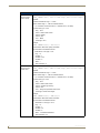
^BMP ............................................................................................................................ 56
^BOR............................................................................................................................. 56
^BPP.............................................................................................................................. 56
^BRD ............................................................................................................................. 57
^BSF.............................................................................................................................. 57
^BSM............................................................................................................................. 57
^BSP.............................................................................................................................. 57
^BWW ........................................................................................................................... 58
^CPF.............................................................................................................................. 58
^DPF ............................................................................................................................. 58
^ENA............................................................................................................................. 58
^FON ............................................................................................................................ 59
^GDI.............................................................................................................................. 59
^GIV .............................................................................................................................. 59
^GLH ............................................................................................................................. 59
^GLL.............................................................................................................................. 60
^GRD............................................................................................................................. 60
^GRU............................................................................................................................. 60
^GSC ............................................................................................................................. 60
^GSN............................................................................................................................. 61
^ICO.............................................................................................................................. 61
^JSB .............................................................................................................................. 62
^JSI ............................................................................................................................... 62
^JST .............................................................................................................................. 63
^SHO............................................................................................................................. 63
^TEC.............................................................................................................................. 63
^TEF .............................................................................................................................. 64
^TXT.............................................................................................................................. 64
^UNI.............................................................................................................................. 64
Button Query Commands .............................................................................................. 65
?BCB.............................................................................................................................. 66
?BCF .............................................................................................................................. 66
?BCT .............................................................................................................................. 67
?BMP ............................................................................................................................. 67
?BOP ............................................................................................................................. 68
?BRD ............................................................................................................................. 68
?BWW............................................................................................................................ 69
?FON ............................................................................................................................. 69
?ICO .............................................................................................................................. 70
?JSB............................................................................................................................... 70
iv
Mio R-4
Table of Contents
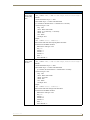
?JSI................................................................................................................................ 71
?JST............................................................................................................................... 71
?TEC .............................................................................................................................. 72
?TEF .............................................................................................................................. 72
?TXT .............................................................................................................................. 73
Remote Run Time Commands ....................................................................................... 74
ABEEP ........................................................................................................................... 74
ADBEEP......................................................................................................................... 74
AKEYR........................................................................................................................... 74
@AKP ............................................................................................................................ 74
@AKR ............................................................................................................................ 74
BEEP.............................................................................................................................. 75
BRIT............................................................................................................................... 75
DBEEP ........................................................................................................................... 75
@EKP............................................................................................................................. 75
PKEYP ........................................................................................................................... 75
@PKP............................................................................................................................. 76
SETUP ........................................................................................................................... 76
SLEEP ............................................................................................................................ 76
@TKP ............................................................................................................................. 76
TPAGEON ..................................................................................................................... 76
TPAGEOFF .................................................................................................................... 76
Input Commands ........................................................................................................... 77
^CAL ............................................................................................................................. 77
@VKB ............................................................................................................................ 77
WAKE............................................................................................................................ 77
Remote Setup Commands............................................................................................. 78
^MUT ............................................................................................................................ 78
@PWD ........................................................................................................................... 78
^PWD............................................................................................................................ 78
Listboxes................................................................................................................. 79
List Box Commands....................................................................................................... 79
^LDN............................................................................................................................. 79
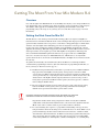
Getting The Most From Your Mio Modero R-4 .................................................87
Overview ................................................................................................................ 87
Getting the Most From the Mio R-4 ....................................................................... 87
The ZigBee Network Calculator.............................................................................. 89
The Mio Modero R-4 Return Button ....................................................................... 90
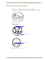
Mio Remote Charging Base ..............................................................................91
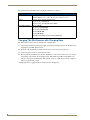
Specifications ......................................................................................................... 91
Mio R-4
v
Table of Contents
Charging The Mio Remote with Charging Base ...................................................... 92
vi
Mio R-4
Mio Modero® R-4 Remote
Mio Modero® R-4 Remote
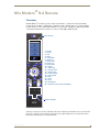
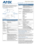
Overview
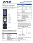
The Mio Modero® R-4 remote provides custom control features, contained in an elegant handheld
rechargeable device(FIG. 1). The Mio R-4 communicates with a NetLinx master via a wireless ZigBee
network: the device comes with installed firmware for connecting to a ZigBee Pro 2007 network, but it
can be updated with firmware to allow it to connect to older ZigBee 2004 networks.
1
Touch Screen
20
19
4
5
6
8
10
9
3
2
7
11
15
13
16
12
14
17
18
1 - Power
2 - Guide
3 - Exit
4 - Menu
5 - Information
6 - Move Up
7 - Move Down
8 - Move Left
9 - Move Right
10 - Select
11 - Volume Up
12 - Volume Down
13 - Channel Up
14 - Channel Down
15 - Last Viewed
16 - Mute
17 - Input
18 - Enter
19 - Back/Home
20 - Up/Down Touch Screen Navigation
Numeric Keypad
FIG. 1 The Mio R-4 (front panel)
Selecting a source device sends a command to the master and runs predetermined events associated with
that source. Selecting a macro will run predefined events, which might not be associated with sources
listed, then return the device to its previous mode.
Mio Modero R-4
1
Mio Modero® R-4 Remote
You will need TPDesign4 to properly program this device. Both the application and its documentation
are available from www.amx.com.
Touch And Tilt Sensor
The Mio R-4 wakes up upon touching the chrome side rails, touching the touch screen, or pressing a
button. If the remote should go to sleep when holding it, you can reawaken the device by tilting it. Errant
jostling, such as bumping a table on which the device rests, will not wake the device unless you are
holding it.
Specifications
The Mio Modero R-4 remote specifications are as follows:
Mio Modero R-4 (FG148-04) Specifications
Dimensions (HWD) 9.50" x 2.00" x .74" (241.3 mm x 50.8 mm x 18.80 mm)
Weight
• .45 lbs (20 g) without batteries
• .55 lbs (25 g) with batteries
Battery
Rechargeable Lithium-Ion
Transmission
Frequencies
ZigBee RF wireless network
Transmission
Range
• 100 feet (30.48m).
Memory
• Refer to the The ZigBee Network Calculator section on page 89 for more information
• 32 Mbytes of FLASH
• 64 Mbytes of SDRAM
Top Components
• LED - blue backlit buttons indicate device is awake
• LCD - high resolution (240x320) 76800 pixels with backlight and touch overlay
• Pushbuttons - the power button is red backlit; the rest are blue backlit buttons.
• 29 buttons total
Rear Components
• Programming Port
• Battery Door
• Rechargeable Battery Connection
Supported
Languages:
Certifications:
• English
• Portuguese
• Japanese
• Spanish
• Arabic
• Thai
• French
• Russian
• Hindi
• Italian
• Greek
• Korean
• German
• Simplified Chinese
• FCC ID: CWU-NXR-MO
• IC: 5078A-NXRMO
• CE
• IEC-60950
• Japan Approval
• Designed for ZigBee
2
Operating
Environment
• Operating Temperature: 0° to 40° C (32° to 104° F)
Included Items
• Mio-RBP Rechargeable Lithium-ion Battery (FG147-10)
• Storage Temperature: -20° to 70° C (-4° to 158° F)
Mio Modero R-4
Mio Modero® R-4 Remote
Mio Modero R-4 (FG148-04) Specifications (Cont.)
Optional Keypads:
• Mio-R4-KP-ITALIAN (FG148-141)
• Mio-R4-KP-FRENCH (FG148-142)
• Mio-R4-KP-ARABIC (FG148-143)
• Mio-R4-KP-CHINESE (FG148-144)
Other AMX
Equipment
• CC-USB Programming cable USB to mini USB (FG10-5965)
• Mio-RCC Charging Base (FG147-02) with power supply
• NXR-ZGW NetLinx ZigBee Gateway (FG5791-01)
• NXR-ZRP NetLinx ZigBee Repeater (FG5791-02)
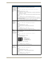
Display Features
The Mio R-4 remote device supports the following display features:
General Buttons
Bargraphs
Multistate General Buttons
Multistate Bargraph Buttons
Joystick Buttons
Animated Icons
List Buttons
Marquee Text
These features can be implemented using TPDesign4 or higher. For details, please refer to the
TPDesign4 online help or Instruction Manual, both available from www.amx.com.
Device Navigation
The Mio R-4 allows you to scroll through pages using the up and down buttons beneath the touch screen.
Pressing the Back buttons moves the selection back by one page while holding the button down returns
the device to the power up page.
Mio Modero R-4
3
Mio Modero® R-4 Remote
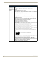
FCC Compliance
This radio module was tested and certified as a stand-alone device according to FCC Rules CFR 47, Part
15, Subpart C. If this device is installed in a manner such that the radio module FCC ID label is not
visible on the outside of the end product, a label must be placed on the end product with the following
statement:
This device complies with Part 15 of the FCC rules. Subject to the following two conditions:
1. This device must not cause harmful interference and
2. This device must accept all interference, including interference that interferes with the operation of
this device. "
The User Manual for the end-device must contain the following statements in a prominent place in the
manual.
“Modifications not expressly approved by the manufacturer will void the user’s authority to operate the
equipment.”
This device has been evaluated and found to be compliant with the FCC Rules for RF
Exposure when the device is operated at a minimum separation distance of 2 cm.
from the user and nearby persons. Operation of this device at closer distances
should be avoided.”
Patents
This product is covered by the following patents:
AMX
U.S. Patent No. D 602,858
U.S. Patent No. D 520,495
U.S. Patent No. 7,786,623
This product employs or practices certain features and/or methods of one or more of the following
patents:
SIPCO, LLC
U.S. Patent No. 7,103,511
U.S. Patent No. 6,914,893
U.S. Patent No. 7,697,492
4
Mio Modero R-4
Mio R-4 Setup
Mio R-4 Setup
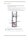
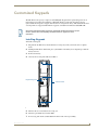
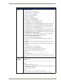
Installing or Replacing the Mio R-4 Lithium-Ion Battery
To install your lithium-ion battery into the Mio R-4:
1. Flip and turn the Mio R-4 so that the buttons are facing away from you and the device is upside
down.
2. Holding the device in both hands, place your thumbs on the battery door and slide the battery door
free. The battery door should slide toward the bottom end of the device.
3. Connect the terminal end of the Lithium Ion battery to the port shown in FIG. 2. It may be necessary
to use a thin, blunt non-conductive object to seat the battery connector fully within its port.
Programming Port
(USB)
Lithium-Ion Battery
Correct path for
battery wires and
connector
Rechargeable
Battery Port
Connection
Rear view battery compartment
FIG. 2 Rechargeable Battery Port on The Mio Remote
Make sure that the battery wires run alongside the battery in the compartment as
shown in FIG. 2. Otherwise, the wires may be damaged or the battery door may not
close properly.
4. Place the battery door back on the device, and slide the door upwards to lock it in place.
Mio Modero R-4
5
Mio R-4 Setup
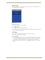
Battery Low Indicator
When the battery charge level is too low to sustain continuous operation, the Mio R-4’s touchscreen will
display a popup window reading “Battery Low” as an initial warning, and then a popup window reading
“Battery Very Low” to encourage the user to shut it down. The device will then shut down to prevent a
total discharge of the battery. To recharge the battery, insert the Mio R-4 into the Mio Remote Charging
Base (see Charging The Mio Remote with Charging Base section on page 92).
6
Mio Modero R-4
Customized Keypads
Customized Keypads
The Mio R-4 has the capacity to replace its default English keypad with an optional keypad in one of
four languages for Arabic, French, Italian, or Mandarin Chinese readers. The keypad may also be
replaced with other keypads to support other functions or arrangements of keys. The additional functions
or arrangements are supported with firmware upgrades, available for download at www.amx.com.
Each of the alternate keypads requires the appropriate firmware download for proper
function; please refer to the Updating Firmware section on page 32 for more
information.
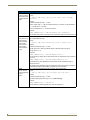
Installing Keypads
To install a new keypad:
1. Flip and turn the Mio R-4 so that the buttons are facing away from you and the device is upside
down.
2. Holding the Mio R-4 in both hands, place your thumbs on the battery door and push up to slide the
battery door free.
3. Remove the battery.
4. Unscrew the 6 screw points indicated in FIG. 3.
Programming Jack
6 Screw Points
FIG. 3 Internal Mio R-4 Components
5. Turn the unit over so the buttons are facing you.
6. Lift the top assembly away from the PCB.
7. If necessary, push out the standard buttons from the front of the top assembly.
Mio Modero R-4
7
Customized Keypads
8. Place the new keypad in the top assembly and verify the alignment with the guide posts on the PCB.
9. Place the top assembly back down on the PCB and turn the unit over again, exposing the 6 screw
points.
10. Tighten the 6 screw points.
11. Install the battery, replace the battery door, and slide the door to lock it in place.
8
Mio Modero R-4
Device Setup Pages
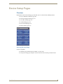
Device Setup Pages
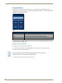
Overview
The Mio R-4 features onboard Setup pages that allow you to set and check the following features:
Project Information functions (page 10)
Remote & Display Settings (page 11)
Date/Time Settings (page 15)
Sound Settings (page 16)
Protected Settings(page 19)
Battery Settings (page 17)
FIG. 4 Setup Page Menu
Accessing the Setup Pages
To enter Setup Menu:
Hold the Input and Back buttons (see FIG. 1) for 6 seconds.
Navigate the Setup pages using the onscreen menu selections and the up and down arrows.
Mio Modero R-4
9
Device Setup Pages
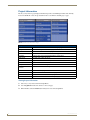
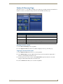
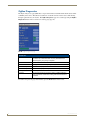
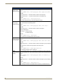
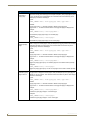
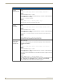
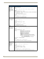
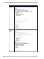
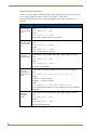
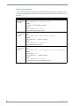
Project Information
The Project Information page displays information specific to the TPDesign4 remote file currently
located on the Mio R-4. Use the up and down arrows to scroll from viewable page to page.
FIG. 5 Mio R-4 Project Information Pages
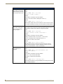
Project Information
File Name
The name of the file as it was created in the designing application.
Designer ID
The ID of the designer for the control pages.
File Revision
The revision number for the control pages.
Dealer ID
The ID of the dealer associated with the control pages.
Job Name
A friendly name for the job associated with the control pages.
Sales Order
The sales order number for the job.
Purchase Order
The purchase order number for the job.
Build Number
The current build version number for the device firmware.
Charger Sensor Port
The port number for the charger sensor.
Charger Sensor
Channel
The channel number for the charger sensor.
Creation Date
The date the control pages were created.
Revision Date
The date of the last revision for the control pages.
Last Save Date
The date of the last save for the control pages.
Job Comments
Any additional comments added in the designing application.
Viewing Project Information
1. Select Project Information from the Setup Menu.
2. Use the Up/Down touchscreen arrows to view each page.
3. When finished, select the Back button until you are out of the Setup Menu.
10
Mio Modero R-4
Device Setup Pages
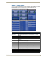
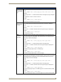
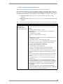
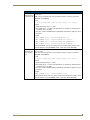
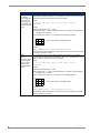
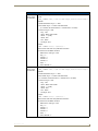
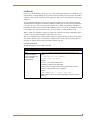
Remote & Display Settings
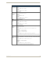
The device provides you with information concerning current displays settings and allows you to edit the
timeout and brightness. Use the up and down arrows to scroll from viewable page to page.
FIG. 6 Remote & Display Settings Pages
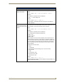
Remote & Display Settings
Mio Modero R-4
Display Timeout
The valid display timeout times are 0, 10, 15, 20, 25, and 30 seconds.
Sleep Timeout
The valid sleep timeout times are 0, 3, 5, 10, 15, 30, 60, 120, 180, and 240
minutes.
LCD
The current brightness of the touchscreen display, between 0 and 100.
Charge LED
The current brightness of the LED displaying charging status, between 0 and 100.
Home Hold Time
The amount of time (in seconds, 0-6) in which the selected home page will be
displayed.
Inactivity
The amount of time (in minutes, 0-240) spent inactive in its charging cradle before
the unit switches to its inactivity page.
Inactivity Page
The selected page displayed when the inactivity timer expires.
Panel Type
The type of unit connected to the ZigBee network. This is always R4.
Firmware Version
The most current firmware version uploaded to the unit.
ZigBee Version
The most current version of the ZigBee module firmware uploaded to the device.
S/N
The device serial number
Setup Pages Version
The current version of the Setup pages uploaded to the unit.
Power-up Page
The page displayed when the unit powers up.
File System
The total and available amounts of storage space in the unit.
RAM
The total amount of available RAM in the unit.
Setup Port
The port (usually 0) used to upload information to the unit.
11
Device Setup Pages
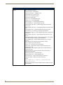
Remote & Display Settings (Cont.)
High Port
The highest port number specified in the project pages.
High Address
The highest address specified in the project pages.
High Channel
The highest channel specified in the project pages.
High Level
The highest level specified in the project pages
Refresh Rate
The refresh rate, in screen lines, of the Setup page screen display.
Screen Width
The width (in pixels) of the Setup page screen display.
Screen Height
The height (in pixels) of the Setup page screen display.
Blink Rate
The rate (in seconds) at which features on the screen will blink.
Wake-up String
The code string chosen by the NetLinx administrator for the unit wake-up.
Sleep String
The code string chosen by the NetLinx administrator for the unit sleep mode.
Start-up String
The code string chosen by the NetLinx administrator for the unit startup.
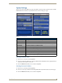
Changing the remote and display settings
The remote has two timeout levels to increase battery life; Display Timeout and Sleep Timeout. By
default, these are set to occur together. For these to occur separately, disable Sleep on Display Timeout.
When the Mio R-4 is in Display Timeout, the device only turns off the display, while the device
otherwise remains fully functional. Its display then comes on immediately upon registering a button or
screen press. Upon Display Timeout, the device will send the sleep string, defined in the TPD4 panel
page properties. to the NetLinx master. Besides turning on from a button or screen press, the device will
also turn on upon receiving a wake command from the Master.
When the unit is in Sleep Timeout, the display is off and the radio is put in low-power mode. In this
mode, the device takes slightly longer to wake up and respond to button presses or message updates from
the master. When the device enters Sleep Timeout at the time specified, it sends a standby event, which is
registered on the gateway and the master.
When the device is touched, it will bring the radio out of low-power mode and send an awake event to
the master. If defined in the TPD4 project properties, a wakeup string is also sent to the master when the
display comes on as the unit comes out of Display Timeout mode.
To change the Display Timeout and Sleep Timeout settings:
1. Select Remote & Display Settings from the Setup Page.
2. Under Display Timeout, use the Up/Down arrows to adjust the timeout period in five-second
increments, to a maximum of 30 seconds.
3. Under Sleep Timeout, use the Up/Down arrows to adjust the timeout period in regular increments, to
a maximum of 240 minutes.
The Sleep Timeout period increments are 0 (sleep timeout disabled, remote will stay
active until the battery charge runs low), 3, 5, 10, 15, 30, 60, 120, 180, and 240
minutes.
4. To disable the default setting and allow separate display and sleep timeouts, press the Sleep on
Display Timeout button. When Sleep on Display Timeout is engaged, the button is green (FIG. 7),
and the Sleep Timeout settings will be greyed out. Press the button again to re-enable the Sleep on
Display Timeout function.
12
Mio Modero R-4
Device Setup Pages
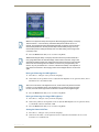
FIG. 7 Sleep on Display Timeout - enabled
Make sure to adjust the Sleep Timeout period after disengaging the Sleep on Display
Timeout function. From the factory, the default sleep timeout will be set for 15
minutes, but engaging and then disengaging the Sleep on Display Timeout function
will reset the period for 0 minutes (will not sleep until the battery charge runs low)
because the previous setting will already have 0 for that setting, even though it was
not actually used.
5. Select the Back button until you are out of the Setup Menu.
While deactivating the Sleep on Display Timeout function will prevent the Mio R-4
from going offline when the selected Display Timeout time is reached, doing so will
decrease the effective battery life. Setting the Sleep Timeout period to 0 will keep the
device from disconnecting from the network, but even a fully charged battery will
reach a very low point within 10 to 14 hours. If the device’s battery is too depleted, it
may need to be returned to the charging cradle and recharged before it can be used
again.
Raising and lowering the LCD brightness
1. Select Remote & Display Settings from the Setup Page.
2. Under LCD, use the Up/Down arrows to adjust the LCD brightness in one-point increments, from a
minimum of 0 to a maximum of 100.
Take care not to set the LCD brightness too low, as the screen may become too dark
to read. If you accidentally set the LCD brightness too low and the screen becomes
too dark, touch the center right of the touchscreen until the screen brightens again.
3. Select the Back button until you are out of the Setup Menu.
Raising and lowering the charge LED brightness
1. Select Remote & Display Settings from the Setup Page.
2. Under Charge LED, use the Up/Down arrows to adjust the LED brightness in one-point increments,
to a minimum of 0 and a maximum of 100.
3. Select the Back button until you are out of the Setup Menu.
Setting the Home Hold Time
1. Select Remote & Display Settings from the Setup Page.
2. Under Home Hold Time, use the Up/Down arrows to adjust the home hold time in one-second
increments, to a maximum of 6.
Mio Modero R-4
13
Device Setup Pages
A setting of 0 has special meaning: it disables the “home” function on button hold,
allowing the back/home button to operate like other external buttons.
3. Select the Back button until you are out of the Setup Menu.
Changing the remote inactivity page flip
1. Select Remote & Display Settings from the Setup Page.
2. Under Inactivity, use the Up/Down arrows to adjust the page flip time in increments, to a maximum
of 240.
3. Select the Back button until you are out of the Setup Menu.
Checking remote display settings
1. Select Remote & Display Settings from the Setup Page.
2. Use the device’s arrow down to navigate to the fourth and fifth Display Settings pages.
3. Select the Back button until you are out of the Setup Menu.
14
Mio Modero R-4
Device Setup Pages
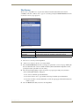
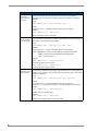
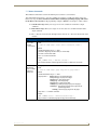
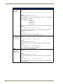
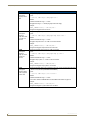
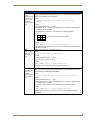
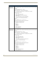
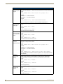
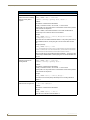
Date/Time Settings
The date and time can be set on the device or you can use the NetLinx Master to establish the time and
format used. Use the up and down arrows to scroll from viewable page to page.
FIG. 8 Date/Time Settings Pages
Date/Time Settings
Get Time & Date
Allows the user to get date and time information from the NetLinx master.
Time Format
Selects between displayed standard and military time formats.
Date Format
Selects displayed date format.
Year
Selects the chosen year for the date.
Month
Selects the chosen month for the date.
Day
Selects the chosen day for the date.
Hour
Selects the chosen hour for the time.
Minute
Selects the chosen minute for the time.
Second
Selects the chosen second for the time.
If the time and date are changed on the Mio R-4 and the device is online with a
NetLinx Master, the time and date will also be changed on the NetLinx Master.
Getting time and date from your NetLinx Master
1. Select Date/Time Settings from the Setup Page.
2. Select Get under Set Date & Time.
3. Select the Back button until you are out of the Setup Menu.
Mio Modero R-4
15
Device Setup Pages
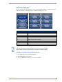
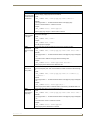
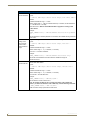
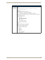
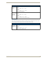
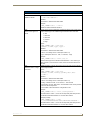
Sound Settings
The device can provide an audible indicator of both hit and miss of button selections.
FIG. 9 Sound Settings Page
Sound Settings
Volume
Adjusts the volume of the sound.
Mute
Silences any button sound.
Play Test
Plays a test tune consisting of a single octave of the musical scale.
Button Hit
Enables or disables the sound of a correctly chosen button.
Button Miss
Enables or disables the sound of an incorrectly chosen button.
Setting the volume
1. Select Sound Settings from the Setup Page.
2. Select the Up and Down arrow under Volume to increase or decrease the sound volume by one
setting. The settings are Mute, Low, Medium, and High.
3. Select the Back button until you are out of the Setup Menu.
Testing the sound settings
1. Select Sound Settings from the Setup Page.
2. Select either the Mute, Button Hit, or Button Miss button. The button will turn green when
properly selected.
3. Push Play Test to test the sound and the volume.
The Mio R-4 will allow the Mute button to be selected along with the Button Hit or
Button Miss buttons. In this case, the Mute button overrides any sound produced by
any of the other buttons.
4. Press the Mute button again until it is no longer green.
5. Select the Back button until you are out of the Setup Menu.
16
Mio Modero R-4
Device Setup Pages
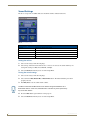
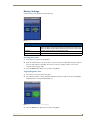
Battery Settings
Check the battery and charging status from this page.
FIG. 10 Battery Settings Pages
Battery Settings
Battery Charge
The quality of the charge is indicated by the number of green lights versus red
lights in the display. The more green lights, the higher the charge. While on the
charger, the Battery Charge indicator will always show a full bar of green lights.
Dock Status
Indicates whether the device is in the charging cradle.
Disable Brightness Limit
Disables limits on the LCD brightness; this will reduce battery life.
Checking Dock Status
1. Select Battery Settings in the Setup Menu.
2. If the Dock Status button is green, the device is seated correctly in its Mio-RCC charging cradle. If
the Dock Status button remains blue, the remote is not in the charging cradle or is not seated
correctly in the charging cradle.
3. Select the Back button until you are out of the Setup Menu.
Toggling Brightness Limit
1. Select Battery Settings from the Setup Page.
2. Select Disable Brightness Limit. The button will turn from green to blue to note that the backlight
brightness limit is no longer disabled (FIG. 11).
FIG. 11 Battery Settings - brightness limit disabled.
3. Select the Back button until you are out of the Setup Menu.
Mio Modero R-4
17
Device Setup Pages
18
Mio Modero R-4
Protected Settings Menu
Protected Settings Menu
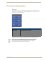
Overview
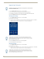
Some of the device settings are security sensitive or change the way the device behaves. These are
considered Protected Settings. The Protected Settings Menu (FIG. 12) is accessed via the Protected
Settings button in the Startup Menu (FIG. 4).
FIG. 12 Protected Settings Pages
Protected Settings Menu
Options & Recovery
Opens the Options & Recovery Page (page 21)
Change Passwords
Opens the Edit Passwords page (page 23)
Calibrate
Opens the Calibrate page (page 24)
System Settings
Opens the System Settings page (page 25)
Reboot Panel
Opens the Reboot Panel page (page 29)
Test Pages
Used to test for dead pixels in the touchscreen (page 29)
Accessing Protected Settings menu items usually requires a password confirmation (FIG. 13).
When accessing the Protected Settings for the first time, the Mio R-4 will request a
password. The default password is 1988. Changing the password after initial access
is highly recommended, and choosing to reset the Mio R-4’s system settings to
factory defaults will return the password to its default as well.
Mio Modero R-4
19
Protected Settings Menu
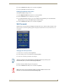
Password Entry
The Password Confirmation page protects the device’s system settings, network information and
calibration from casual changes. Use the Numeral Keypad pushbuttons (FIG. 1) to enter passwords. The
unit allows only numeric passwords.
FIG. 13 Password Confirmation Page
Password Confirmation
Back:
Goes to the Password Entry page
Clear:
Clears the entry field
Abort:
Shuts down the Password page without submitting a password
Done:
Submits the password
The default password is 1988, which has to be entered in the text entry field upon opening the Password
Confirmation page for the first time.
Entering a numeric password
1. Select Protected Settings in the Setup Menu.
2. Press any button on the Protected Settings Menu to invoke the Password Confirmation page.
3. Enter your password from the keypad.
Should you decide to leave the Password Confirmation page for any reason, press
the Exit button (FIG. 1) to return to the last page displayed.
4. After entering a password, select Done to submit it.
20
Mio Modero R-4
Protected Settings Menu
Options & Recovery Page
The Options & Recovery page (FIG. 14) enables you to enable page tracking and function identification
features, as well as to reset system settings and remove all currently loaded user pages.
FIG. 14 Options & Recovery Page
Options & Recovery
Device Number
The device’s NetLinx Device Number.
Function Show
When enabled, displays the function codes for each button push.
Page Tracking
When enabled, reports all page flips to the NetLinx master.
Reset System Settings
Returns all systems settings to factory defaults.
Remove User Pages
Removes any custom designed control pages.
Protection
Enables or disables Front Button Setup Access
Checking the device number
1. Select Protected Settings in the Setup Menu.
2. Select Options & Recovery. The device number is displayed at the top of the first page.
Toggling the Function Show option
1. Select Options & Recovery in the Protected Settings Menu.
2. Select Function Show. Not only will the button turn green, but every button or display with a
function code will display that function code.
3. To turn off the Function Show feature, select Function Show again. The function codes will
disappear and the button will return to its normal color.
4. Select the Back button until you are out of the Setup Menu.
Mio Modero R-4
21
Protected Settings Menu
Toggling the Page Tracking option
The NetLinx master will track all page flips if the String handler for the device Data
event is set in the NetLinx code.
1. Select Options & Recovery in the Protected Settings Menu.
2. Select Page Tracking; page tracking will start when the button turns green.
3. To disable page tracking, select Page Tracking again, and the button will return to blue.
4. Select the Back button until you are out of the Setup Menu.
Resetting System Settings
1. Select Options & Recovery in the Protected Settings Menu.
2. Select Reset System Settings.
3. At the page reading “Confirmation: Are sure you want to reset all system settings?”, select Yes to
confirm your selection or No to return to the Protected Settings Page (FIG. 15).
FIG. 15 Reset Systems Settings dialog page
The Yes button will be disabled for five seconds after this page opens, with a
countdown appearing at the top right of the screen. After the countdown, the Yes
button will change from gray to blue.
4. Select the Back button until you are out of the Setup Menu.
5. Press the Yes button to reboot the device.
Removing User Pages
1. Select Options & Recovery in the Protected Settings Menu.
2. Select Remove User Pages.
3. At the page reading “Confirmation: Are you sure you want to remove all user pages?”, select Yes to
confirm your selection or No to return to the Protected Settings Main Page.
The Yes button will be disabled for five seconds after this page opens, with a
countdown appearing at the top right of the screen. After the countdown, the Yes
button will change from gray to its normal color.
22
Mio Modero R-4
Protected Settings Menu
4. Select the Back button until you are out of the Setup Menu.
5. Press the Yes button to reboot the device.
Enabling Front Button Setup Access
To enable Front Button Setup Access:
1. Select Options & Recovery in the Protected Settings Menu.
2. Press the Down arrow to access the Protection page.
3. To enable Front Button Setup Access, press the button, which will turn green. To disable Front
Button Setup Access, press the button again to return it to blue.
4. Select the Back button until you are out of the Setup Menu.
Edit Passwords
The Edit Passwords page manages multiple passwords for the device. The first four passwords can be
used to protect access to the specific pages in each project. Password 5 is for access to the Protected
Setup pages.
FIG. 16 Edit Passwords Page
Changing the device password
1. Select Protected Settings in the Setup Menu.
2. Select Change Passwords on the Protected Settings Menu.
3. Select one of the five passwords to be changed.
Should you decide to leave the Password Confirmation page for any reason, press
the Exit button (FIG. 1) to return to the last page displayed.
4. Enter, edit and confirm changes to the password.
5. Select the Back button until you are out of the Setup Menu.
Make sure to save a copy of Password 5 after it is changed. Without access to the
password, you cannot access the Protected Settings page.
Mio Modero R-4
23
Protected Settings Menu
Calibrate
To make sure that button selections behave as expected, calibrating the touch screen area may be
necessary. The system will ask the user to touch crosshairs that appear in different portions of the screen.
FIG. 17 Calibrate page
Calibrating the touch screen area
1. Select Calibrate from the Protected Settings Menu.
2. Touch each target that appears on the screen.
3. If successfully calibrated, the Mio R-4 will return you to the Protected Settings Menu.
Alternate methods for accessing the calibration page:
Press and hold the Input and Back buttons (FIG. 1) for 9 seconds.
Touch and hold the touchscreen during a reboot (see the Reboot Page section on page 29 for
details) and release when the Calibrate page appears.
Hold the Calibrate button until the page flips to the Calibrate page. When on that page, a set
of crosshairs will go wherever the touch is registered.
24
Mio Modero R-4
Protected Settings Menu
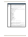
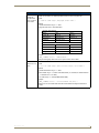
System Settings
The System Settings pages (FIG. 18) provide you with the connection status, gateway selection, and RF
link information. Use the device’s up and down arrows to move from page to page.
FIG. 18 System Settings Pages
Status
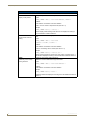
Status
Green light indicates the overall connection is good.
Connected to System
Shows the number of the connected system.
Master IP
The IP of the connected master.
Icsp Mode
The mode used for wireless communication. This is always defaulted to “ZigBee”.
Device Number
The number of the device in the NetLinx system.
Gateway IP
The IP for the Gateway providing the connection.
Gateway EUI Address
The EUI Address for the Gateway providing the connection.
Device EUI
A ZigBee network ID unique to the device.
Extended PANID
The ID for the ZigBee personal area network.
Network Scan
This button opens the Site Survey page (FIG. 19).
ZigBee Diagnostic
This button opens the ZigBee Diagnostics page (FIG. 20).
Checking connection status
1. Select Protected Settings in the Setup Menu.
2. Select System Settings in the Protected Settings Menu. If the round button at the top right of the first
page is green, the system is connected.
3. Select the Back button until you are out of the Setup Menu.
Checking the master IP address
1. Select Protected Settings in the Setup Menu.
2. Select System Settings in the Protected Settings Menu. The master IP is indicated on the first page.
3. Select the Back button until you are out of the Setup Menu.
Mio Modero R-4
25
Protected Settings Menu
Checking the gateway IP address
1. Select Protected Settings in the Setup Menu.
2. Select System Settings in the Protected Settings Menu. The gateway IP is indicated on the second
page.
3. Select the Back button until you are out of the Setup Menu.
Checking the Gateway EUI address
1. Select Protected Settings in the Setup menu.
2. Select System Settings in the Protected Settings Menu.
3. Select the device’s down arrow to navigate to the second page. The Gateway EUI address is
indicated on the second page.
4. Select the Back button until you are out of the Setup Menu.
Checking the Extended PAN ID
1. Select Protected Settings in the Setup Menu.
2. Select System Settings in the Protected Settings Menu.
3. Select the device’s down arrow to navigate to the second page. The Extended PAN ID is indicated at
the bottom of the page, above the Network Scan and ZigBee Statistics buttons.
4. Select the Back button until you are out of the Setup Menu.
Changing the Device Number
1. Select Protected Settings in the Setup Menu.
2. Select System Settings in the Protected Settings Menu.
3.
The Device Number button at the bottom of the first page lists the current NetLinx Device Number
for the unit.
4. To change the device number, press the Device Number button to open the Device Number page.
5. Enter the new device number with the device keypad.
To move the cursor back one number at a time, press the Back button.
To clear the entire device number field, press the Clear button.
To return to the System Settings page without saving any changes, press the Abort button.
To save any changes and return to the System Settings page, press the Done button.
6. Reboot the Mio R-4 from the Reboot Page (see the Reboot Page section on page 29).
In addition to the Abort button, should you decide not to change the Device Number
for any reason, press the Back button (FIG. 1) to return to the last page displayed.
7. Select the Back button until you are out of the Setup Menu.
26
Mio Modero R-4
Protected Settings Menu
Site Survey
The Site Survey page (FIG. 19) is a report of the wireless networks found and the status of their
availability to the device. The Site Survey page is accessed by pressing the Network Scan button on the
second System Settings page (page 25).
FIG. 19 Site Survey page
Site Survey
Extended PAN ID
The Personal Area Network ID.
Join
The availability of the network. Yes indicates that it is open to join.
Stack Profile
The Stack Profile indicates the capabilities of that wireless network.
Joining a wireless network
1. Select Protected Settings in the Setup Menu.
2.
Select System Settings in the Protected Settings Menu.
3. Press the Network Scan button on the second page to open the Wireless Networks page. Pushing the
Extended PAN ID header sorts the available networks by Extended PAN ID in alphabetical order;
pressing the header again will reverse the sorting.
4. Select the network by pushing it on the touch screen. A pop-up page reading “Do you wish to
connect to PAN [PAN number]” will appear.
To connect to the PAN, press the Yes button.
To return to the Site Survey page without connecting to the PAN, press the No button.
If you do not make a selection within three seconds, the pop-up page will automatically close
in three seconds.
5. Select the Back button until you return to the Setup Menu.
Mio Modero R-4
27
Protected Settings Menu
ZigBee Diagnostics
The ZigBee Diagnostics page (FIG. 20) is a report of the wireless networks found and the status of their
availability to the device. This allows assessment of a network connection to the device while moving
through a particular area, for instance. The ZigBee Diagnostics page is accessed by pressing the ZigBee
Diagnostics button on the second System Settings page (page 25)
FIG. 20 ZigBee Diagnostics page
RF Link Info
Parent ID:
The ID number of the ZigBee gateway currently being contacted by
the device. Any number other than “0” (zero) indicates that the
network signal is going through a repeater.
Pan ID:
The PAN ID number of the device.
Channel:
The ZigBee channel currently being used by the device.
TX Link Quality
The connection quality for transmission.
RX Link Quality
The connection quality for reception.
Latency:
The delay detected in the network connection.
Progress:
This scroll bar shows the progress of finding a ZigBee PAN within
range of the device. Continuous scrolling means that the device is
connected.
To return to the previous page when finished, press the Back button on the remote.
28
Mio Modero R-4
Protected Settings Menu
Reboot Page
Some changes to the device settings require a reboot before the changes are accepted. This may be
accessed through the Reboot page (FIG. 21).
FIG. 21 Reboot Page
Rebooting the device
1. Select Protected Settings from the Setup Page.
2. Select Reboot Panel.
3. Select Reboot. The device will reboot and restart.
4. To calibrate the touchscreen, touch and hold the touchscreen during the reboot and release when the
Calibrate Test page (page 24) appears.
Test Pages
The Test Pages are for testing the Mio R-4’s touchscreen. To check the touchscreen:
1. Select Protected Settings from the Setup Page.
2. Select Test Pages.
3. The subsequent displayed pages are all one color, intended to differentiate touchscreen pixels that
may no longer be functioning. After checking each colored page, touch the screen to move to the
next colored page. The pages run through blue, green, red, white, black, and then blue again.
4. When finished inspecting the colored pages, select the Back button until you are out of the Setup
Menu.
Mio Modero R-4
29
Protected Settings Menu
30
Mio Modero R-4
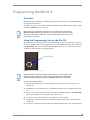
Programming the Mio R-4
Programming the Mio R-4
Overview
Most functionality of the Mio R-4 is handled using the application TPDesign4. Go to www.amx.com for
the supporting documentation.
The Mio R-4 recognizes a select number of NetLinx Commands. For a full list and descriptions, consult
the SEND_COMMANDs section on page 41.
Before doing any programming for the Mio R-4, you must download and install the
latest AMX USB LAN driver from www.amx.com. The user will be required to install
the driver, put the device in USB mode, and connect the device to the computer prior
to any upload or download.
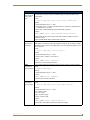
Using the Programming Jack on the Mio R-4
The programming jack located on the back of the Mio R-4 (FIG. 22) is used for communication between
the device and AMX software. The programming jack uses a CC-USB Programming cable, USB to mini
USB (FG10-5965), which can be ordered from AMX. Make sure the device is situated in the charging
cradle before starting download of configuration files.
Programming Jack
FIG. 22 The Mio R-4 Programming Jack
USB file transfers should only be performed while the unit is on the charging cradle
and with the sleep timeout set to 0 (off). Set the sleep timeout (in the Setup Menu,
Remote and Display Settings->Timeout) to 0 BEFORE attaching the USB cable.
To download Configuration Files:
1. Flip and turn the Mio R-4 device so that the buttons are facing away from you and the device is
upside down.
2. Holding the device in both hands, place your thumbs on the battery door and slide the battery door
free.
3. Place the device in the charging cradle and connect the mini USB programming cable (FG10-5965)
into the programming jack on the back side of the remote device.
4. Connect the other end of the USB cable to the USB port on your computer.
5. Configure the communication parameters in NetLinx Studio or File Transfer 2 and download the
resultant file.
6. Disconnect the USB cable after the download. The Mio R-4 will self-reboot after the file download.
Mio Modero R-4
31
Programming the Mio R-4
Downloading Configuration Files through TPDesign4
TPDesign4 may also be used to download configuration files to the Mio R-4. To download files directly
from TPDesign4:
1. Place the device in the charging cradle and connect the mini USB programming cable (FG10-5965)
into the programming jack on the back side of the remote device.
2. Connect the other end of the USB cable to the USB port on your computer.
3. In TPDesign4, select Transfer->Connect...
4. Wait until the connection icon in the Mio R-4 setup pages turns green.
5. Select Transfer to device in TPDesign4.
If the Mio R-4's connection icon does not turn green within 10-15 seconds of enabling
the virtual NetLinx master (“Refresh System” in NetLinx Studio, “Connect...” in
TPDesign4), unplug the device for at least 5 seconds and then reconnect it.
Updating Firmware
Main Mio R-4 firmware updates are only available at this time via USB connection to the Virtual
NetLinx Master.
Updating Mio R-4 Firmware Through USB
To update the main firmware for the Mio R-4:
1. Connect the Mio R-4 to your computer via the USB programming jack (FIG. 22).
2. Open NetLinx Studio.
3. Connect to the Virtual NetLinx Master.
4. Select Tools > Firmware Transfer.
5. Choose the firmware file to be transferred.
6. Enter the Mio R-4’s Device ID.
7. Select Send.
8. The unit reboots after the upgrade and enters un-archiving mode, during which the AMX logo is
displayed and the POWER LED continuously flashes. The unit reboots again after un-archiving
with the new firmware running.
If you are using the Mio R-4 in conjunction with other ZigBee-enabled devices, such
as the Mio R-3 and the NXR-ZGW wireless gateway, you should update the ZigBee
firmware to all of the ZigBee devices at the same time.
32
Mio Modero R-4
Programming the Mio R-4
USB
NetLinx Studio can be set up to run a Virtual Master where the PC acts as the Master by supplying its
own IP Address for communication to the Mio R-4. For a PC to establish a USB connection with a Mio
R-4, it must have the AMX USBLAN driver installed.
The AMX USBLAN driver for Windows XP can be downloaded as a stand-alone
application from www.amx.com.
Prepare your PC for USB communication with the Mio R-4
If you haven’t already done so, download and install the latest versions of NetLinx Studio and
TPDesign4 (from www.amx.com), and restart your PC.
Configure a Virtual NetLinx Master using NetLinx Studio
A Virtual NetLinx Master (VNM) is used when the target Mio R-4 is not connected to a physical
NetLinx Master. In this situation, the PC takes on the functions of a Master via a Virtual NetLinx Master.
This connection is made by either using the PC’s Ethernet Address (via TCP/IP using a known PC’s IP
Address as the Master) or using a direct mini-USB connection to communicate directly to the Mio R-4.
Before beginning:
1. Download the latest AMX USB LAN driver from www.amx.com.
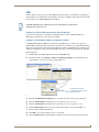
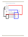
2. In NetLinx Studio, select Settings > Master Communication Settings, from the Main menu to
open the Master Communication Settings dialog (FIG. 23).
IP Address of computer
(not needed as this is a direct
USB connection)
FIG. 23 Assigning Communication Settings for a Virtual Master
3. Click the Communications Settings button to open the Communications Settings dialog box.
4. Click the NetLinx Master radio button (from the Platform Selection section).
5. Click the Virtual Master radio button (from the Transport Connection Option section).
6. Click the Edit Settings button to open the Virtual NetLinx Master Settings dialog (FIG. 23).
7. Enter the System number (default is 1).
8. Click OK to close all open dialogs and save your settings.
9. Click the OnLine Tree tab in the Workspace window to view the devices on the Virtual System.
Mio Modero R-4
33
Programming the Mio R-4
10. Right-click on Empty Device Tree/System and select Refresh System to re-populate the list.
The Mio R-4 will not appear as a device below the virtual system number (in the Online Tree tab)
until both the system number (default = 1) is entered into the Master Connection section of the
System Settings page and the Mio R-4 is restarted.
The Connection status turns green after a few seconds to indicate an active USB connection to
the PC (Virtual Master).
If the System Connection icon does not turn green, check the USB connection and
communication settings and refresh the system.
34
Mio Modero R-4
Programming the Mio R-4
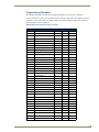
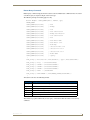
Programming Numbers
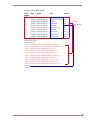
The following information provides the programming numbers for colors, fonts, and borders.
Colors can be used to set the colors on buttons, sliders, and pages. The lowest color number represents
the lightest color-specific display; the highest number represents the darkest display. For example, 0
represents light red, and 5 is dark red.
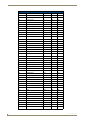
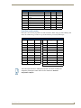
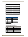
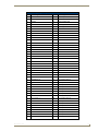
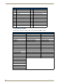
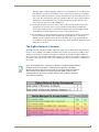
RGB triplets and names for basic 88 colors
RGB Values for all 88 Basic Colors
Mio Modero R-4
Index No. Name
Red
Green
Blue
00
Very Light Red
255
0
0
01
Light Red
223
0
0
02
Red
191
0
0
03
Medium Red
159
0
0
04
Dark Red
127
0
0
05
Very Dark Red
95
0
0
06
Very Light Orange
255
128
0
07
Light Orange
223
112
0
08
Orange
191
96
0
09
Medium Orange
159
80
0
10
Dark Orange
127
64
0
11
Very Dark Orange
95
48
0
12
Very Light Yellow
255
255
0
13
Light Yellow
223
223
0
14
Yellow
191
191
0
15
Medium Yellow
159
159
0
16
Dark Yellow
127
127
0
17
Very Dark Yellow
95
95
0
18
Very Light Lime
128
255
0
19
Light Lime
112
223
0
20
Lime
96
191
0
21
Medium Lime
80
159
0
22
Dark Lime
64
127
0
23
Very Dark Lime
48
95
0
24
Very Light Green
0
255
0
25
Light Green
0
223
0
26
Green
0
191
0
27
Medium Green
0
159
0
28
Dark Green
0
127
0
29
Very Dark Green
0
95
0
30
Very Light Mint
0
255
128
31
Light Mint
0
223
112
32
Mint
0
191
96
33
Medium Mint
0
159
80
34
Dark Mint
0
127
64
35
Very Dark Mint
0
95
48
36
Very Light Cyan
0
255
255
35
Programming the Mio R-4
RGB Values for all 88 Basic Colors (Cont.)
36
Index No. Name
Red
Green
Blue
37
Light Cyan
0
223
223
38
Cyan
0
191
191
39
Medium Cyan
0
159
159
40
Dark Cyan
0
127
127
41
Very Dark Cyan
0
95
95
42
Very Light Aqua
0
128
255
43
Light Aqua
0
112
223
44
Aqua
0
96
191
45
Medium Aqua
0
80
159
46
Dark Aqua
0
64
127
47
Very Dark Aqua
0
48
95
48
Very Light Blue
0
0
255
49
Light Blue
0
0
223
50
Blue
0
0
191
51
Medium Blue
0
0
159
52
Dark Blue
0
0
127
53
Very Dark Blue
0
0
95
54
Very Light Purple
128
0
255
55
Light Purple
112
0
223
56
Purple
96
0
191
57
Medium Purple
80
0
159
58
Dark Purple
64
0
127
59
Very Dark Purple
48
0
95
60
Very Light Magenta
255
0
255
61
Light Magenta
223
0
223
62
Magenta
191
0
191
63
Medium Magenta
159
0
159
64
Dark Magenta
127
0
127
65
Very Dark Magenta
95
0
95
66
Very Light Pink
255
0
128
67
Light Pink
223
0
112
68
Pink
191
0
96
69
Medium Pink
159
0
80
70
Dark Pink
127
0
64
71
Very Dark Pink
95
0
48
72
White
255
255
255
73
Grey1
238
238
238
74
Grey3
204
204
204
75
Grey5
170
170
170
76
Grey7
136
136
136
77
Grey9
102
102
102
78
Grey4
187
187
187
79
Grey6
153
153
153
80
Grey8
119
119
119
Mio Modero R-4
Programming the Mio R-4
RGB Values for all 88 Basic Colors (Cont.)
Index No. Name
Red
Green
Blue
81
Grey10
85
85
85
82
Grey12
51
51
51
83
Grey13
34
34
34
84
Grey2
221
221
221
85
Grey11
68
68
68
86
Grey14
17
17
17
87
Black
0
0
0
255
TRANSPARENT
99
53
99
Fixed Fonts and ID numbers
Font styles can be used to program the text fonts on buttons, sliders, and pages. The following chart
shows the default font type and their respective ID numbers generated by TPDesign4.
Fixed Fonts and ID Numbers
Font ID
#
Font type
Size
Font ID
#
Font type
Size
1
Courier New
9
19
Arial
9
2
Courier New
12
20
Arial
10
3
Courier New
18
21
Arial
12
4
Courier New
26
22
Arial
14
5
Courier New
32
23
Arial
16
6
Courier New
18
24
Arial
18
7
Courier New
26
25
Arial
20
8
Courier New
34
26
Arial
24
9
AMX Bold
14
27
Arial
36
10
AMX Bold
20
28
Arial Bold
10
11
AMX Bold
36
29
Arial Bold
8
32 - Variable Fonts start at 32.
You must import fonts into a TPDesign4 project file. The font ID numbers are
assigned by TPDesign4. These values are also listed in the Generate
Programmer’s Report.
Mio Modero R-4
37
Programming the Mio R-4
Slider/Cursor Names
Slider/Cursor Names
Bargraph Slider Names
Joystick Cursor Names
None
None
Ball
Arrow
Circle -L
Ball
Circle -M
Circle
Circle -S
Crosshairs
Precision
Gunsight
Rectangle -L
Hand
Rectangle -M
Metal
Rectangle -S
Spiral
Smart Button Bubbled - L
Smart Button Bubbled
Smart Button Bubbled - S
Target
Windows
View Finder
Windows Active
Border Styles by Numbers
Border styles can be used to program borders on buttons, sliders, and popup pages.
Border Styles by Numbers
No.
Border styles
No.
Border styles
0-1
No border
10-11
Picture frame
2
Single line
12
Double line
3
Double line
20
Bevel-S
4
Quad line
21
Bevel-M
5-6
Circle 15
22-23
Circle 15
7
Single line
24-27
Neon inactive-S
8
Double line
40-41
Diamond 55
9
Quad line
The TPDesign4 Touch Panel Design program has pre-set border styles that are user selectable.
You cannot use the following number values for programming purposes when changing border styles.
TPD4 border styles can ONLY be changed by using the name.
TPD4 Border Styles by Name
38
No.
Border styles
No.
Border styles
1
None
22
Circle 155
2
AMX Elite -L
23
Circle 165
3
AMX Elite -M
24
Circle 175
4
AMX Elite -S
25
Circle 185
5
Bevel -L
26
Circle 195
6
Bevel -M
27
Cursor Bottom
7
Bevel -S
28
Cursor Bottom with Hole
8
Circle 15
29
Cursor Top
Mio Modero R-4
Programming the Mio R-4
TPD4 Border Styles by Name (Cont.)
Mio Modero R-4
No.
Border styles
No.
Border styles
9
Circle 25
30
Cursor Top with Hole
10
Circle 35
31
Cursor Left
11
Circle 45
32
Cursor Left with Hole
12
Circle 55
33
Cursor Right
13
Circle 65
34
Cursor Right with Hole
14
Circle 75
35
Custom Frame
15
Circle 85
36
Diamond 15
16
Circle 95
37
Diamond 25
17
Circle 105
38
Diamond 35
18
Circle 115
39
Diamond 45
19
Circle 125
40
Diamond 55
20
Circle 135
41
Diamond 65
21
Circle 145
42
Diamond 75
43
Diamond 85
85
Menu Bottom Rounded 65
44
Diamond 95
86
Menu Bottom Rounded 75
45
Diamond 105
87
Menu Bottom Rounded 85
46
Diamond 115
88
Menu Bottom Rounded 95
47
Diamond 125
89
Menu Bottom Rounded 105
48
Diamond 135
90
Menu Bottom Rounded 115
49
Diamond 145
91
Menu Bottom Rounded 125
50
Diamond 155
92
Menu Bottom Rounded 135
51
Diamond 165
93
Menu Bottom Rounded 145
52
Diamond 175
94
Menu Bottom Rounded 155
53
Diamond 185
95
Menu Bottom Rounded 165
54
Diamond 195
96
Menu Bottom Rounded 175
55
Double Bevel -L
97
Menu Bottom Rounded 185
56
Double Bevel -M
98
Menu Bottom Rounded 195
57
Double Bevel -S
99
Menu Top Rounded 15
58
Double Line
100
Menu Top Rounded 25
59
Fuzzy
101
Menu Top Rounded 35
60
Glow-L
102
Menu Top Rounded 45
61
Glow-S
103
Menu Top Rounded 55
62
Help Down
104
Menu Top Rounded 65
63
Neon Active -L
105
Menu Top Rounded 75
64
Neon Active -S
106
Menu Top Rounded 85
65
Neon Inactive -L
107
Menu Top Rounded 95
66
Neon Inactive -S
108
Menu Top Rounded 105
67
Oval H 60x30
109
Menu Top Rounded 115
68
Oval H 100x50
110
Menu Top Rounded 125
69
Oval H 150x75
111
Menu Top Rounded 135
70
Oval H 200x100
112
Menu Top Rounded 145
71
Oval V 30x60
113
Menu Top Rounded 155
72
Oval V 50x100
114
Menu Top Rounded 165
73
Oval V 75x150
115
Menu Top Rounded 175
39
Programming the Mio R-4
TPD4 Border Styles by Name (Cont.)
No.
Border styles
No.
Border styles
74
Oval V 100x200
116
Menu Top Rounded 185
75
Picture Frame
117
Menu Top Rounded 195
76
Quad Line
118
Menu Right Rounded 15
77
Single Line
119
Menu Right Rounded 25
78
Windows Style Popup
120
Menu Right Rounded 35
79
Windows Style Popup (Status Bar)
121
Menu Right Rounded 45
80
Menu Bottom Rounded 15
122
Menu Right Rounded 55
81
Menu Bottom Rounded 25
123
Menu Right Rounded 65
82
Menu Bottom Rounded 35
124
Menu Right Rounded 75
83
Menu Bottom Rounded 45
125
Menu Right Rounded 85
84
Menu Bottom Rounded 55
126
Menu Right Rounded 95
Text Effects Names
The following is a listing of text effects names associated with the ^TEF command.
Text Effects
• Glow -S
• Medium Drop Shadow 1
• Hard Drop Shadow 1
• Glow -M
• Medium Drop Shadow 2
• Hard Drop Shadow 2
• Glow -L
• Medium Drop Shadow 3
• Hard Drop Shadow 3
• Glow -X
• Medium Drop Shadow 4
• Hard Drop Shadow 4
• Outline -S
• Medium Drop Shadow 5
• Hard Drop Shadow 5
• Outline -M
• Medium Drop Shadow 6
• Hard Drop Shadow 6
• Outline -L
• Medium Drop Shadow 7
• Hard Drop Shadow 7
• Outline -X
• Medium Drop Shadow 8
• Hard Drop Shadow 8
• Soft Drop Shadow 1
• Medium Drop Shadow 1 with outline • Hard Drop Shadow 1 with outline
• Soft Drop Shadow 2
• Medium Drop Shadow 2 with outline • Hard Drop Shadow 2 with outline
• Soft Drop Shadow 3
• Medium Drop Shadow 3 with outline • Hard Drop Shadow 3 with outline
• Soft Drop Shadow 4
• Medium Drop Shadow 4 with outline • Hard Drop Shadow 4 with outline
• Soft Drop Shadow 5
• Medium Drop Shadow 5 with outline • Hard Drop Shadow 5 with outline
• Soft Drop Shadow 6
• Medium Drop Shadow 6 with outline • Hard Drop Shadow 6 with outline
• Soft Drop Shadow 7
• Medium Drop Shadow 7 with outline • Hard Drop Shadow 7 with outline
• Soft Drop Shadow 8
• Medium Drop Shadow 8 with outline • Hard Drop Shadow 8 with outline
• Soft Drop Shadow 1 with outline
• Soft Drop Shadow 2 with outline
• Soft Drop Shadow 3 with outline
• Soft Drop Shadow 4 with outline
• Soft Drop Shadow 5 with outline
• Soft Drop Shadow 6 with outline
• Soft Drop Shadow 7 with outline
• Soft Drop Shadow 8 with outline
40
Mio Modero R-4
Programming the Mio R-4
SEND_COMMANDs
Below is a list of SEND_COMMANDs accepted by the Mio R-4 from NetLinx masters. To use these
commands, establish a Telnet session from the PC to the NetLinx master. Additionally, you could use
NetLinx Studio 2.4 or the master’s web page to send the commands.
All text is based on a Unicode index.
Page Commands
Page Commands are used in the NetLinx Programming Language and are case insensitive.
Page Commands
PAGE
Flip to a specified
page
Flips to a page with a specified page name. If the page is currently active, it will not redraw
the page.
Syntax:
"'PAGE-<page name>'"
Variables:
• page name = 1 - 50 ASCII characters. Name of the page the popup is displayed On.
Example:
SEND_COMMAND Device,"'PAGE-Page1'"
Flips to page1.
@APG
Add a specific popup page to a specified popup group. Add the popup page to a group if it
Add a popup page does not already exist. If the new popup is added to a group which has a popup displayed
to a popup group on the current page along with the new pop-up, the displayed popup will be hidden and
the new popup will be displayed.
Syntax:
SEND_COMMAND <DEV>,"'@APG-<popup page name>;<popup group name>'"
Variables:
• popup page name = 1 - 50 ASCII characters. Name of the popup page.
• popup group name = 1 - 50 ASCII characters. Name of the popup group.
Example:
SEND_COMMAND Device,"'@APG-Popup1;Group1'"
Adds the popup page 'Popup1' to the popup group 'Group1'.
@CPG
Clear all popup pages from a specified popup group.
Clear all popup
pages from a
popup group
Syntax:
SEND_COMMAND <DEV>,"'@CPG-<popup group name>'"
Variable:
• popup group name = 1 - 50 ASCII characters. Name of the popup group.
Example:
SEND_COMMAND Device,"'@CPG-Group1'"
Clears all popup pages from the popup group 'Group1'.
Mio Modero R-4
41
Programming the Mio R-4
Page Commands (Cont.)
@DPG
Delete a specific popup page from a specified popup group if it exists.
Delete a popup
Syntax:
page from a group SEND_COMMAND <DEV>,"'@DPG-<popup page name>;<popup group name>'"
Variables:
• popup page name = 1 - 50 ASCII characters. Name of the popup page.
• popup group name = 1 - 50 ASCII characters. Name of the popup group.
Example:
SEND_COMMAND Device,"'@DPG-Popup1;Group1'"
Deletes the popup page 'Popup1' from the popup group 'Group1'.
@PDR
Set the popup
location reset flag
Set the popup location reset flag. If the flag is set, the popup will return to its default location on show instead of its last drag location.
Syntax:
SEND_COMMAND <DEV>,"'@PDR-<popup page name>;<reset flag>'"
Variables:
• popup page name = 1 - 50 ASCII characters. Name of the page the
• popup is displayed On.
• reset flag = 1 = Enable reset flag
0 = Disable reset flag
Example:
SEND_COMMAND Device,"'@PDR-Popup1'"
Popup1 will return to its default location when turned On.
@PHE
Set the hide effect for the specified popup page to the named hide effect.
Set the hide effect Syntax:
for a popup page
SEND_COMMAND <DEV>,"'@PHE-<popup page name>;<hide effect name>'"
Variables:
• popup page name = 1 - 50 ASCII characters. Name of the page the popup is displayed
On.
• hide effect name = Refers to the popup effect names being used.
Example:
SEND_COMMAND Panel,"'@PHE-Popup1;Slide Left'"
Sets the Popup1 hide effect name to 'Slide Left'.
@PHP
Set the hide effect position. Only 1 coordinate is ever needed for an effect, however the
Set the hide effect command will specify both. This command sets the location at which the effect will end at.
position
Syntax:
SEND_COMMAND <DEV>,"'@PHP-<popup page name>;<x coordinate>,<y
coordinate>'"
Variable:
• popup page name = 1 - 50 ASCII characters. Name of the page the popup is displayed
On.
Example:
SEND_COMMAND Device,"'@PHP-Popup1;75,0'"
Sets the Popup1 hide effect x-coordinate value to 75 and the y-coordinate value to 0.
42
Mio Modero R-4
Programming the Mio R-4
Page Commands (Cont.)
@PHT
Set the hide effect time for the specified popup page.
Set the hide effect Syntax:
time for a popup
SEND_COMMAND <DEV>,"'@PHT-<popup page name>;<hide effect time>'"
page
Variables:
• popup page name = 1 - 50 ASCII characters. Name of the page the popup is displayed
On.
• hide effect time = Given in 1/10ths of a second.
Example:
SEND_COMMAND Device,"'@PHT-Popup1;50'"
Sets the Popup1 hide effect time to 5 seconds.
@PPA
Close all popups
on a page
Close all popups on a specified page. If the page name is empty, the current page is used.
This command works in the same way as the 'Clear Page' command in TPDesign4.
Syntax:
SEND_COMMAND <DEV>,"'@PPA-<page name>'"
Variable:
• page name = 1 - 50 ASCII characters. Name of the page the popup is displayed On.
Example:
SEND_COMMAND Device,"'@PPA-Page1'"
Close all popups on Page1.
@PPF
Deactivate a
popup page
Deactivate a specific popup page on either a specified page or the current page. If the
page name is empty, the current page is used (see example 2). If the popup page is part of
a group, the whole group is deactivated. This command works in the same way as the
'Hide popup' command in TPDesign4.
Syntax:
SEND_COMMAND <DEV>,"'@PPF-<popup page name>;<page name>'"
Variables:
• popup page name = 1 - 50 ASCII characters. Name of the popup page.
• page name = 1 - 50 ASCII characters. Name of the page the popup is displayed On.
Example 1:
SEND_COMMAND Device,"'@PPF-Popup1;Main'"
Deactivates the popup page 'Popup1' on the Main page.
Example 2:
SEND_COMMAND Device,"'@PPF-Popup1'"
Deactivates the popup page 'Popup1' on the current page.
@PPG
Toggle a popup
page
Toggle a specific popup page on either a specified page or the current page. If the page
name is empty, the current page is used (see example 2). Toggling refers to the activating/
deactivating (On/Off) of a popup page. This command works in the same way as the
'Toggle Popup' command in TPDesign4.
Syntax:
SEND_COMMAND <DEV>,"'@PPG-<popup page name>;<page name>'"
Variables:
• popup page name = 1 - 50 ASCII characters. Name of the popup page.
• page name = 1 - 50 ASCII characters. Name of the page the popup is displayed On.
Example:
SEND_COMMAND Device,"'@PPG-Popup1;Main'"
Toggles the popup page 'Popup1' on the 'Main' page from one state to another (On/Off).
Example 2:
SEND_COMMAND Device,"'@PPG-Popup1'"
Toggles the popup page 'Popup1' on the current page from one state to another (On/Off).
Mio Modero R-4
43
Programming the Mio R-4
Page Commands (Cont.)
@PPK
Deactivate a
popup page from
all pages
Kill a specific popup page from all pages. Kills refers to the deactivating (Off) of a popup
window from all pages. If the pop-up page is part of a group, the whole group is
deactivated. This command works in the same way as the 'Clear Group' command in
TPDesign4.
Syntax:
SEND_COMMAND <DEV>,"'@PPK-<popup page name>'"
Variable:
• popup page name = 1 - 50 ASCII characters. Name of the popup page.
Example:
SEND_COMMAND Device,"'@PPK-Popup1'"
Kills the popup page 'Popup1' on all pages.
@PPM
Set the modality
for a popup page
Set the modality for a specific popup page to either Modal or Non-Modal. A Modal popup
page, when active, only allows you to use the buttons and features on that popup page. All
other buttons on the panel page are inactivated.
Syntax:
SEND_COMMAND <DEV>,"'@PPM-<popup page name>;<mode>'"
Variables:
• popup page name = 1 - 50 ASCII characters. Name of the popup page.
• mode = NONMODAL converts a previously Modal popup page to a NonModal.
MODAL converts a previously NonModal popup page to Modal.
modal = 1 and non-modal = 0
Examples:
SEND_COMMAND Device,"'@PPM-Popup1;Modal'"
Sets the popup page 'Popup1' to Modal.
SEND_COMMAND Device,"'@PPM-Popup1;1'"
Sets the popup page 'Popup1' to Modal.
@PPN
Activate a popup
page to launch
Activate a specific popup page to launch on either a specified page or the current page. If
the page name is empty, the current page is used (see example 2). If the popup page is
already on, do not re-draw it. This command works in the same way as the 'Show Popup'
command in TPDesign4.
Syntax:
SEND_COMMAND <DEV>,"'@PPN-<popup page name>;<page name>'"
Variables:
• popup page name = 1 - 50 ASCII characters. Name of the popup page.
• page name = 1 - 50 ASCII characters. Name of the page the popup is displayed On
Example:
SEND_COMMAND Device,"'@PPN-Popup1;Main'"
Activates 'Popup1' on the 'Main' page.
Example 2:
SEND_COMMAND Device,"'@PPN-Popup1'"
Activates the popup page 'Popup1' on the current page.
44
Mio Modero R-4
Programming the Mio R-4
Page Commands (Cont.)
@PPT
Set a specific popup page to timeout within a specified time. Timeout is in 1/10 seconds. If
timeout is empty, popup page will clear the timeout.
Set a popup page
to timeout within a Syntax:
specified time
SEND_COMMAND <DEV>,"'@PPT-<popup page name>;<timeout>'"
Variables:
• popup page name = 1 - 50 ASCII characters. Name of the popup page.
• timeout = timeout duration in 1/10ths of a second.
Example:
SEND_COMMAND Device,"'@PPT-Popup1;30'"
Sets the popup page 'Popup1' to timeout within 3 seconds.
@PPX
Close all popups
on all pages
Close all popups on all pages. This command works in the same way as the 'Clear All'
command in TPDesign4.
Syntax:
SEND_COMMAND <DEV>,"'@PPX'"
Example:
SEND_COMMAND Panel,"'@PPX'"
Close all popups on all pages.
@PSE
Set the show effect for the specified popup page to the named show effect.
Set the show
effect for a popup
page
Syntax:
SEND_COMMAND <DEV>,"'@PSE-<popup page name>;<show effect name>'"
Variables:
• popup page name = 1 - 50 ASCII characters. Name of the page the popup is displayed
On.
• show effect name = Refers to the popup effect name being used.
Example:
SEND_COMMAND Device,"'@PSE-Popup1;Slide from Left'"
Sets the Popup1 show effect name to 'Slide from Left'.
@PSP
Set the show
effect position
Set the show effect position. Only 1 coordinate is ever needed for an effect, however the
command will specify both. This command sets the location at which the effect will begin
at.
Syntax:
SEND_COMMAND <DEV>,"'@PSP-<popup page name>;<x coordinate>,<y
coordinate>'"
Variable:
• popup page name = 1 - 50 ASCII characters. Name of the page the popup is displayed
On.
Example:
SEND_COMMAND Device,"'@PSP-Popup1;100,0'"
Sets the Popup1 show effect x-coordinate value to 100 and the y-coordinate value to 0.
@PST
Set the show effect time for the specified popup page.
Set the show
effect time for a
popup page
Syntax:
SEND_COMMAND <DEV>,"'@PST-<popup page name>;<show effect time>'"
Variables:
• popup page name = 1 - 50 ASCII characters. Name of the page the popup is displayed
On.
• show effect time = Given in 1/10ths of a second.
Example:
SEND_COMMAND Device,"'@PST-Popup1;50'"
Sets the Popup1 show effect time to 5 seconds.
Mio Modero R-4
45
Programming the Mio R-4
Page Commands (Cont.)
PPOF
Deactivate a
popup page
Deactivate a specific popup page on either a specified page or the current page. If the
page name is empty, the current page is used (see example 2). If the popup page is part of
a group, the whole group is deactivated. This command works in the same way as the
'Hide Popup' command in TPDesign4.
Syntax:
SEND_COMMAND <DEV>,"'PPOF-<popup page name>;<page name>'"
Variables:
• popup page name = 1 - 50 ASCII characters. Name of the popup page.
• page name = 1 - 50 ASCII characters. Name of the page the popup is displayed On.
Example:
SEND_COMMAND Device,"'PPOF-Popup1;Main'"
Deactivates the popup page 'Popup1' on the Main page.
Example 2:
SEND_COMMAND Device,"'PPOF-Popup1'"
Deactivates the popup page 'Popup1' on the current page.
PPOG
Toggle a popup
page.
Toggle a specific popup page on either a specified page or the current page. If the page
name is empty, the current page is used (see example 2). Toggling refers to the activating/
deactivating (On/Off) of a popup page. This command works in the same way as the
'Toggle Popup' command in TPDesign4.
Syntax:
SEND_COMMAND <DEV>,"'PPOG-<popup page name>;<page name>'"
Variables:
• popup page name = 1 - 50 ASCII characters. Name of the popup page.
• page name = 1 - 50 ASCII characters. Name of the page the popup is displayed On.
Example:
SEND_COMMAND Device,"'PPOG-Popup1;Main'"
Toggles the popup page 'Popup1' on the Main page from one state to another (On/Off).
Example 2:
SEND_COMMAND Device,"'PPOG-Popup1'"
Toggles the popup page 'Popup1' on the current page from one state to another (On/Off).
PPON
Activate a popup
page to launch.
Activate a specific popup page to launch on either a specified page or the current page. If
the page name is empty, the current page is used (see example 2). If the popup page is
already On, do not re-draw it. This command works in the same way as the 'Show Popup'
command in TPDesign4.
Syntax:
SEND_COMMAND <DEV>,"'PPON-<popup page name>;<page name>'"
Variable:
• popup page name = 1 - 50 ASCII characters. Name of the popup page.
• page name = 1 - 50 ASCII characters. Name of the page the popup is displayed On.
Example:
SEND_COMMAND Device,"'PPON-Popup1;Main'"
Activates the popup page 'Popup1' on the Main page.
Example 2:
SEND_COMMAND Device,"'PPON-Popup1'"
Activates the popup page 'Popup1' on the current page.
46
Mio Modero R-4
Programming the Mio R-4
“^” Button Commands with Embedded Codes
These Button Commands are used in the NetLinx protocol and are case insensitive.
All commands that begin with “^” have the capability of assigning a variable text address range and
button state range. A device must first be defined in the NetLinx programming language with values
for the Device: Port: System (in all programming examples - Remote is used in place of these values).
Variable text ranges allow you to target 1 or more variable text channels in a single
command.
Button State ranges allow you to target 1 or more states of a variable text button with a single
command.
The "." Character is used for the 'through' notation, also the "&" character is used for the 'And' notation.
"^" Button Commands with Embedded Codes
^BMF
Set any/all button
parameters by sending
embedded codes and data.
Syntax:
"'^BMF-<vt addr range>,<button states range>,<data>'"
Variables:
• variable text address char array = 1 - 4000.
• button states range = 1 - 256 for multi-state buttons (0 = All states, for
General buttons
1 = Off state and 2 = On state).
• level range = 1 - 600 (level value is 1 - 65535).
• data:
• ’%B<border style>’ = Set the border style name. See theBorder Styles by
Numbers table on page 38.
• ’%B’,<border 0-27,40,41> = Set the border style number.
• ’%DO<1-5><1-5><1-5><1-5><1-5> = Set the draw order. Listed from bottom
to top. Refer to the ^BDO command on page 52 for more information.
• ’%F’,<font 1-8,10,11,20-29,32-xx> = Set the font.
• ’%F<font 01-08,10,11,20-29,32-xx>’ = Set the font.
• ’%MI<mask image>’ = Set the mask image.
• ’%T<text >’ = Set the text using ASCII characters (empty is clear).
• ’%P<bitmap>’ = Set the picture/bitmap filename (empty is clear).
• ’%I’,<icon 01-9900, 0-clear>’ = Set the icon using values of 01 - 9900 (icon
numbers are assigned in the TPDesign4 Resource Manager tab - Slots
section).
• ’%I<icon 01-9900, 0-clear>’ = Set the icon using values of 01 - 9900 (icon
numbers are assigned in the TPDesign4 Resource Manager tab - Slots
section).
• ’%J’,<alignment of text 1-9> = As shown the following telephone keypad
alignment chart:
• ’%JT<alignment of text 0-9>’ = As shown the above telephone keypad
alignment chart, BUT the 0 (zero) is absolute and followed by ’,<left>,<top>’
• ’%JB<alignment of bitmap/picture 0-9>’ = As shown the above telephone
keypad alignment chart BUT the 0 (zero) is absolute and followed by
’,<left>,<top>’
• ’%JI<alignment of icon 0-9>’ = As shown the above telephone keypad
alignment chart, BUT the 0 (zero) is absolute and followed by ’,<left>,<top>’
• '%R<left>,<top>,<right>,<bottom>' = Set rectangle.
Mio Modero R-4
47
Programming the Mio R-4
"^" Button Commands with Embedded Codes
^BMF
(Cont.)
For some of these commands and values, refer to theRGB Values for all 88
Basic Colors table on page 35.
• ’%CF<on fill color>’ = Set Fill Color.
• ’%CB<on border color>’ = Set Border Color.
• ’%CT<on text color>’ = Set Text Color.
• ’%SW<1 or 0>’ = Show/hide a button.
• ’%ST<style>’ = Button style.
• ’%EN<1 or 0>’ = Enable/disable a button.
• ’%WW<1 or 0>’ = Word wrap ON/OFF.
• ’%GH<bargraph hi>’ = Set the bargraph upper limit.
• ’%GL<bargraph low>’ = Set the bargraph lower limit.
• ’%GN<bargraph slider name>’ = Set the bargraph slider name/Joystick
cursor name.
• ’%GC<bargraph slider color>’ = Set the bargraph slider color/Joystick cursor
color.
• ’%GI<bargraph invert>’ = Set the bargraph invert/noninvert or joystick
coordinate (0,1,2,3). ^GIV section on page 59 more information.
• ’%GU<bargraph ramp up>’ = Set the bargraph ramp up time in intervals of 1/
10 second.
• ’%GD<bargraph ramp down>’ = Set the bargraph ramp down time in 1/10
second.
• ’%GG<bargraph drag increment> = Set the bargraph drag increment. Refer
to the ^GDI command on page 59 for more information.
• ’%OT<feedback type>’ = Set the Feedback (Output) Type to one of the
following:
None, Channel,Invert, ON (Always ON), Momentary, or Blink.
• ’%SM’ = Submit a text for text area button.
• ’%SF<1 or 0>’ = Set the focus for text area button.
• ’%OP<0-255>’ = Set the button opacity to either Invisible (value=0) or
Opaque (value=255).
• ’%OP#<00-FF>’ = Set the button opacity to either Invisible (value=00) or
Opaque (value=FF).
• ’%UN<Unicode text>’ = Set the Unicode text. See the^UNI section on
page 64 for the text format.
• ’%EF<text effect name>’ = Set the text effect.
• ’%EC<text effect color>’ = Set the text effect color.
• ’%ML<max length>’ = Set the maximum length of a text area.
• ’%MK<input mask>’ = Set the input mask of a text area.
Example:
SEND_COMMAND Device,"'^BMF-500,1,%B10%CFRed%CB Blue
%CTBlack%Ptest.png'"
Sets the button OFF state as well as the Border, Fill Color, Border Color, Text
Color, and Bitmap.
48
Mio Modero R-4
Programming the Mio R-4
“^” Button Commands
These Button Commands are used in the NetLinx protocol and are case insensitive.
All commands that begin with "^" have the capability of assigning a variable text address range and
button state range. A device must first be defined in the NetLinx programming language with values
for the Device: Port: System (in all programming examples - Remote is used in place of these values).
Variable text ranges allow you to target one or more variable text channels in a single
command.
Button State ranges allow you to target one or more states of a variable text button with a
single command.
The “.” Character is used for the 'through' notation, also the “&” character is used for the 'And'
notation.
"^" Button Commands
^ANI
Run a button animation (in 1/10 second).
Run a button
animation
(in 1/10 second)
Syntax:
"'^ANI-<vt addr range>,<start state>,<end state>,<time>'"
Variable:
• variable text address range = 1 - 4000.
• start state = Beginning of button state (0= current state).
• end state = End of button state.
• time = In 1/10 second intervals.
Example:
SEND_COMMAND Panel,"'^ANI-500,1,25,100'"
Runs a button animation at text range 500 from state 1 to state 25 for 10 second.
^APF
Add page flip action to a button if it does not already exist.
Add page flip
action to a button
if it does not
already exist
Syntax:
"'^APF-<vt addr range>,<page flip action>,<page name>'"
Variable:
• variable text address range = 1 - 4000.
• page flip action =
Stan[dardPage] - Flip to standard page
Prev[iousPage] - Flip to previous page
Show[Popup] - Show Popup page
Hide[Popup] - Hide Popup page
Togg[lePopup] - Toggle popup state
ClearG[roup] - Clear popup page group from all pages
ClearP[age] - Clear all popup pages from a page with the
specified page name
ClearA[ll] - Clear all popup pages from all pages
• page name = 1 - 50 ASCII characters.
Example:
SEND COMMAND Device,"'^APF-400,Stan,Main Page'"
Assigns a button to a standard page flip with page name 'Main Page'.
Mio Modero R-4
49
Programming the Mio R-4
"^" Button Commands (Cont.)
^BAT
Append non-unicode text.
Append
non-unicode text
Syntax:
"'^BAT-<vt addr range>,<button states range>,<new text>'"
Variable:
• variable text address range = 1 - 4000.
• button states range = 1 - 256 for multi-state buttons (0 = All states, for General buttons
1 = Off state and 2 = On state).
• new text = 1 - 50 ASCII characters.
Example:
SEND_COMMAND Device,"'^BAT-520,1,Enter City'"
Appends the text 'Enter City' to the button’s OFF state.
^BAU
Append unicode text. Same format as ^UNI.
Append
unicode text
Syntax:
"'^BAU-<vt addr range>,<button states range>,<unicode text>'"
Variable:
• variable text address range = 1 - 4000.
• button states range = 1 - 256 for multi-state buttons (0 = All states, for General buttons
1 = Off state and 2 = On state).
• unicode text = 1 - 50 ASCII characters. Unicode characters must be entered in Hex
format.
Example:
SEND_COMMAND Device,"'^BAU-520,1,00770062'"
Appends Unicode text '00770062' to the button’s OFF state.
^BCB
Set the border
color to the
specified color
Set the border color to the specified color only if the specified border color is not the same
as the current color.
Note: Color can be assigned by color name (without spaces), number or R,G,B value
(RRGGBB or RRGGBBAA).
Syntax:
"'^BCB-<vt addr range>,<button states range>,<color value>'"
Variable:
• variable text address range = 1 - 4000.
• button states range = 1 - 256 for multi-state buttons (0 = All states, for General buttons
1 = Off state and 2 = On state).
• color value = Refer to theRGB Values for all 88 Basic Colors table on page 35 for more
information.
Example:
SEND_COMMAND Device,"'^BCB-500.504&510,1,12'"
Sets the Off state border color to 12 (Yellow). Colors can be set by Color Numbers, Color
name, R,G,B,alpha colors (RRGGBBAA) and R, G & B colors values (RRGGBB).
Refer to theRGB Values for all 88 Basic Colors table on page 35.
50
Mio Modero R-4
Programming the Mio R-4
"^" Button Commands (Cont.)
^BCF
Set the fill color to the specified color only if the specified fill color is not the same as the
current color.
Set the fill color to
the specified color Note: Color can be assigned by color name (without spaces), number or R,G,B value
(RRGGBB or RRGGBBAA).
Syntax:
"'^BCF-<vt addr range>,<button states range>,<color value>'"
Variable:
• variable text address range = 1 - 4000.
• button states range = 1 - 256 for multi-state buttons (0 = All states, for General buttons
1 = Off state and 2 = On state).
• color value = Refer to theRGB Values for all 88 Basic Colors table on page 35 for more
information.
Example:
SEND_COMMAND Device,"'^BCF-500.504&510.515,1,12'"
SEND_COMMAND Device,"'^BCF-500.504&510.515,1,Yellow'"
SEND_COMMAND Device,"'^BCF-500.504&510.515,1,#F4EC0A63''"
SEND_COMMAND Device,"'^BCF-500.504&510.515,1,#F4EC0A'"
Sets the Off state fill color by color number. Colors can be set by Color Numbers, Color
name, R,G,B,alpha colors (RRGGBBAA) and R, G & B colors values (RRGGBB).
^BCT
Set the text color
to the specified
color.
Set the text color to the specified color only if the specified text color is not the same as
the current color.
Note: Color can be assigned by color name (without spaces), number or R,G,B value
(RRGGBB or RRGGBBAA).
Syntax:
"'^BCT-<vt addr range>,<button states range>,<color value>'"
Variable:
• variable text address range = 1 - 4000.
• button states range = 1 - 256 for multi-state buttons (0 = All states, for General buttons
1 = Off state and 2 = On state).
• color value = Refer to theRGB Values for all 88 Basic Colors table on page 35 for more
information.
Example:
SEND_COMMAND Device,"'^BCT-500.504&510,1,12'"
Sets the Off state border color to 12 (Yellow). Colors can be set by Color Numbers, Color
name, R,G,B,alpha colors (RRGGBBAA) and R, G & B colors values (RRGGBB).
Mio Modero R-4
51
Programming the Mio R-4
"^" Button Commands (Cont.)
^BDO
Determines what order each layer of the button is drawn.
Set the button
draw order
Syntax:
"'^BDO-<vt addr range>,<button states range>,<1-5><1-5><1-5><15><1-5>'"
Variable:
• variable text address range = 1 - 4000.
• button states range = 1 - 256 for multi-state buttons (0 = All states, for General buttons
1 = Off state and 2 = On state).
• layer assignments = Fill Layer
= 1
Image Layer = 2
Icon Layer = 3
Text Layer = 4
Border Layer = 5
Note: The layer assignments are from bottom to top. The default draw order is 12345.
Example:
SEND_COMMAND Device,"'^BDO-530,1&2,51432'"
Sets the button’s variable text 530 ON/OFF state draw order (from bottom to top) to
Border, Fill, Text, Icon, and Image.
Example 2:
SEND_COMMAND Device,"'^BDO-1,0,12345'"
Sets all states of a button back to its default drawing order.
^BFB
Set the feedback type of the button. ONLY works on General-type buttons.
Set the feedback
type of the button
Syntax:
"'^BFB-<vt addr range>,<feedback type>'"
Variables:
• variable text address range = 1 - 4000.
• feedback type = (None, Channel, Invert, On (Always on), Momentary, and Blink).
Example:
SEND_COMMAND Remote,"'^BFB-500,Momentary'"
Sets the Feedback type of the button to 'Momentary'.
^BIM
Set the input mask for the specified address.
Set the input
Syntax:
mask for the
"'^BIM-<vt addr range>,<input mask>'"
specified address.
Variable:
• variable text address range = 1 - 4000.
• input mask = Refer to the Input Commands section on page 77 for character types.
Example:
SEND_COMMAND Device,"'^BIM-500,AAAAAAAAAA'"
Sets the input mask to ten ’A’ characters, that are required, to either a letter or digit
(entry is required).
52
Mio Modero R-4
Programming the Mio R-4
"^" Button Commands (Cont.)
^BMC
Copy attributes of the source button to all the destination buttons.
Copy attributes of
the source button
to all the
destination
buttons.
Note that the source is a single button state. Each state must be copied as a separate
command. The <codes> section represents what attributes will be copied. All codes are
2 char pairs that can be separated by comma, space, percent or just ran together.
Syntax:
"'^BMC-<vt addr range>,<button states range>,<source
port>,<source address>,<source state>,<codes>'"
Variable:
• variable text address range = 1 - 4000.
• button states range = 1 - 256 for multi-state buttons (0 = All states, for General buttons
1 = Off state and 2 = On state).
• source port = 1 - 100.
• source address = 1 - 4000.
• source state = 1 - 256.
codes:
BM - Picture/Bitmap
BR - Border
CB - Border Color
CF - Fill Color
CT - Text Color
EC - Text effect color
EF - Text effect
FT - Font
IC - Icon
JB - Bitmap alignment
JI - Icon alignment
JT - Text alignment
LN - Lines of video removed
OP - Opacity
TX - Text
WW - Word wrap on/off
Example:
SEND_COMMAND Device,"'^BMC-425,1,1,500,1,BR'"
or
SEND_COMMAND Device,"'^BMC-425,1,1,500,1,%BR'"
Copies the OFF state border of button with a variable text address of 500 onto the OFF
state border of button with a variable text address of 425.
Example 2:
SEND_COMMAND Device,"'^BMC-150,1,1,315,1,%BR%FT%TX%BM%IC%CF%CT'"
Copies the OFF state border, font, Text, bitmap, icon, fill color and text color of the button
with a variable text address of 315 onto the OFF state border, font, Text, bitmap, icon, fill
color and text color of the button with a variable text address of 150.
Mio Modero R-4
53
Programming the Mio R-4
"^" Button Commands (Cont.)
^BMF
Set any/all button parameters by sending embedded codes and data.
Set any/all button
parameters by
sending
embedded codes
and data
Syntax:
"'^BMF-<vt addr range>,<button states range>,<data>'"
Variables:
• variable text address char array = 1 - 4000.
• button states range = 1 - 256 for multi-state buttons (0 = All states, for General buttons
1 = Off state and 2 = On state).
• level range = 1 - 600 (level value is 1 - 65535).
• data:
• ’%B<border style>’ = Set the border style name. See theBorder Styles by Numbers table
on page 38.
• ’%B’,<border 0-27,40,41> = Set the borer style number. See theBorder Styles by
Numbers table on page 38.
• ’%DO<1-5><1-5><1-5><1-5><1-5> = Set the draw order. Listed from bottom to top.
Refer to the ^BDO command on page 52 for more information.
• ’%F’,<font 1-8,10,11,20-29,32-xx> = Set the font.
• ’%F<font 01-08,10,11,20-29,32-xx>’ = Set the font.
• ’%MI<mask image>’ = Set the mask image. Refer to the ^BMI command on page 55 for
more information.
• ’%T<text >’ = Set the text using ASCII characters (empty is clear).
• ’%P<bitmap>’ = Set the picture/bitmap filename (empty is clear).
• ’%I’,<icon 01-9900, 0-clear>’ = Set the icon using values of 01 - 9900 (icon numbers are
assigned in the TPDesign4 Resource Manager tab - Slots section).
• ’%I<icon 01-9900, 0-clear>’ = Set the icon using values of 01 - 9900 (icon numbers are
assigned in the TPDesign4 Resource Manager tab - Slots section).
• ’%J’,<alignment of text 1-9> = As shown the following telephone keypad alignment
chart:
0
1
2
3
4
5
6
7
8
9
Zero can be used for an absolute position
• ’%JT<alignment of text 0-9>’ = As shown the above telephone keypad alignment chart,
BUT the 0 (zero) is absolute and followed by ’,<left>,<top>’
• ’%JB<alignment of bitmap/picture 0-9>’ = As shown the above telephone keypad
alignment chart BUT the 0 (zero) is absolute and followed by ’,<left>,<top>’
• ’%JI<alignment of icon 0-9>’ = As shown the above telephone keypad alignment chart,
BUT the 0 (zero) is absolute and followed by ’,<left>,<top>’
• '%R<left>,<top>,<right>,<bottom>' = Set rectangle.
54
Mio Modero R-4
Programming the Mio R-4
"^" Button Commands (Cont.)
^BMF
(Cont.)
For some of these commands and values, refer to theRGB Values for all 88 Basic
Colors table on page 35.
• ’%CF<on fill color>’ = Set Fill Color.
• ’%CB<on border color>’ = Set Border Color.
• ’%CT<on text color>’ = Set Text Color.
• ’%SW<1 or 0>’ = Show/hide a button.
• ’%ST<style>’ = Button style.
• ’%EN<1 or 0>’ = Enable/disable a button.
• ’%WW<1 or 0>’ = Word wrap ON/OFF.
• ’%GH<bargraph hi>’ = Set the bargraph upper limit.
• ’%GL<bargraph low>’ = Set the bargraph lower limit.
• ’%GN<bargraph slider name>’ = Set the bargraph slider name/Joystick cursor name.
• ’%GC<bargraph slider color>’ = Set the bargraph slider color/Joystick cursor color.
• ’%GI<bargraph invert>’ = Set the bargraph invert/noninvert or joystick coordinate
(0,1,2,3). ^GIV section on page 59 more information.
• ’%GU<bargraph ramp up>’ = Set the bargraph ramp up time in intervals of 1/10 second.
• ’%GD<bargraph ramp down>’ = Set the bargraph ramp down time in 1/10 second.
• ’%GG<bargraph drag increment> = Set the bargraph drag increment. Refer to the ^GDI
command on page 59 for more information.
• ’%OT<feedback type>’ = Set the Feedback (Output) Type to one of the following:
None, Channel,Invert, ON (Always ON), Momentary, or Blink.
• ’%SM’ = Submit a text for text area button.
• ’%SF<1 or 0>’ = Set the focus for text area button.
• ’%OP<0-255>’ = Set the button opacity to either Invisible (value=0) or Opaque
(value=255).
• ’%OP#<00-FF>’ = Set the button opacity to either Invisible (value=00) or Opaque
(value=FF).
• ’%UN<Unicode text>’ = Set the Unicode text. See the^UNI section on page 64 for the
text format.
• ’%EF<text effect name>’ = Set the text effect.
• ’%EC<text effect color>’ = Set the text effect color.
• ’%ML<max length>’ = Set the maximum length of a text area.
• ’%MK<input mask>’ = Set the input mask of a text area.
Example:
SEND_COMMAND Device,"'^BMF-500,1,%B10%CFRed%CB Blue
%CTBlack%Ptest.png'"
Sets the button OFF state as well as the Border, Fill Color, Border Color, Text Color, and
Bitmap.
^BMI
Set the button
mask image
Mask image is used to crop a borderless button to a non-square shape. This is typically
used with a bitmap.
Syntax:
"'^BMI-<vt addr range>,<button states range>,<mask image>'"
Variable:
• variable text address range = 1 - 4000.
• button states range = 1 - 256 for multi-state buttons (0 = All states, for General buttons
1 = Off state and 2 = On state).
• mask image = Graphic file used.
Example:
SEND_COMMAND Device,"'^BMI-530,1&2,newMac.png'"
Sets the button with variable text 530 ON/OFF state mask image to 'newmac.png'.
Mio Modero R-4
55
Programming the Mio R-4
"^" Button Commands (Cont.)
^BMP
Assign a picture to those buttons with a defined address range.
Assign a picture to Syntax:
those buttons with
"'^BMP-<vt addr range>,<button states range>,<name of bitmap/
a defined address
picture>'"
range
Variable:
• variable text address range = 1 - 4000.
• button states range = 1 - 256 for multi-state buttons (0 = All states, for General buttons
1 = Off state and 2 = On state).
• name of bitmap/picture = 1 - 50 ASCII characters.
Example:
SEND_COMMAND Device,"'^BMP-500.504&510.515,1,bitmap.png'"
Sets the OFF state picture for the buttons with variable text ranges of 500-504 & 510-515.
^BOR
Set a border to a
specific border
style associated
with a border
value for those
buttons with a
defined address
range
Set a border to a specific border style associated with a border value for those buttons
with a defined address range.
Syntax:
"'^BOR-<vt addr range>,<border style name or border value>'"
Variable:
• variable text address range = 1 - 4000.
• border style name = Refer to theBorder Styles by Numbers table on page 38.
• border value = 0 - 41.
Examples:
SEND_COMMAND Device,"'^BOR-500.504&510.515,10'"
Sets the border by number (#10) to those buttons with the variable text range of 500-504
& 510-515.
SEND_COMMAND Device,"'^BOR-500.504&510,AMX Elite -M'"
Sets the border by name (AMX Elite) to those buttons with the variable text range of
500-504 & 510-515.
The border style is available through the TPDesign4 border-style drop-down list. Refer to
theTPD4 Border Styles by Name table on page 38 for more information.
^BPP
Set or clear the protected page flip flag of a button. Zero clears the flag.
Syntax:
Set or clear the
protected page flip
"'^BPP-<vt addr range>,<protected page flip flag value>'"
flag of a
Variable:
button
• variable text address range = 1 - 4000.
• protected page flip flag value range = 0 - 4 (0 clears the flag).
Example:
SEND_COMMAND Device,"'^BPP-500,1'"
Sets the button to protected page flip flag 1 (sets it to password 1).
56
Mio Modero R-4
Programming the Mio R-4
"^" Button Commands (Cont.)
^BRD
Set the border of
a button state/
states
Set the border of a button state/states only if the specified border is not the same as the
current border. The border names are available through the TPDesign4 border-name
drop-down list.
Syntax:
"'^BRD-<vt addr range>,<button states range>,<border name>'"
Variable:
• variable text address range = 1 - 4000.
• button states range = 1 - 256 for multi-state buttons (0 = All states, for General buttons
1 = Off state and 2 = On state).
• border name = Refer toBorder Styles by Numbers table on page 38.
Example:
SEND_COMMAND Device,"'^BRD-500.504&510.515,1&2,Quad Line'"
Sets the border by name (Quad Line) to those buttons with the variable text range of
500-504 & 510-515.
Refer to theTPD4 Border Styles by Name table on page 38.
^BSF
Set the focus to the text area.
Set the focus to
the text area
Note: Select one button at a time (single variable text address). Do not assign a variable
text address range to set focus to multiple buttons. Only one variable text address can be
in focus at a time.
Syntax:
"'^BSF-<vt addr range>,<selection value>'"
Variable:
• variable text address range = 1 - 4000.
• selection value = Unselect = 0 and select = 1.
Example:
SEND_COMMAND Device,"'^BSF-500,1'"
Sets the focus to the text area of the button.
^BSM
This command causes the text areas to send their text as strings to the NetLinx Master.
Submit text for
text area buttons.
Syntax:
"'^BSM-<vt addr range>'"
Variable:
• variable text address range = 1 - 4000.
Example:
SEND_COMMAND Device,"'^BSM-500'"
Submits the text of the text area button.
^BSP
Set the button size and its position on the page.
Set the button
size and position
Syntax:
"'^BSP-<vt addr range>,<left>,<top>,<right>,<bottom>'"
Variable:
• variable text address range = 1 - 4000.
• left = left side of page.
• top = top of page.
• right = right side of page.
• bottom = bottom of page.
Example:
SEND_COMMAND Device,"'^BSP-530,left,top'"
Sets the button with variable text 530 in the left side top of page.
Mio Modero R-4
57
Programming the Mio R-4
"^" Button Commands (Cont.)
^BWW
Set the button
word wrap
feature to those
buttons with a
defined address
range.
Set the button word wrap feature to those buttons with a defined address range. By
default, word-wrap is Off.
Syntax:
"'^BWW-<vt addr range>,<button states range>,<word wrap>'"
Variable:
• variable text address range = 1 - 4000.
• button states range = 1 - 256 for multi-state buttons (0 = All states, for General buttons
1 = Off state and 2 = On state).
• word wrap = (0=Off and 1=On). Default is Off.
Example:
SEND_COMMAND Device,"'^BWW-500,1,1'"
Sets the word wrap on for the button’s Off state.
^CPF
Clear all page flips from a button.
Clear all page flips Syntax:
from a button
"'^CPF-<vt addr range>'"
Variables:
• variable text address range = 1 - 4000.
Example:
SEND_COMMAND Remote,"'^CPF-500'"
Clears all page flips from the button.
^DPF
Delete page flips from button if it already exists.
Delete page flips
from button if it
already exists
Syntax:
"'^DFP-<vt addr range>,<actions>,<page name>'"
Variable:
• variable text address range = 1 - 4000.
• actions =
Stan[dardPage] - Flip to standard page
Prev[iousPage] - Flip to previous page
Show[Popup] - Show Popup page
Hide[Popup] - Hide Popup page
Togg[lePopup] - Toggle popup state
ClearG[roup] - Clear popup page group from all pages
ClearP[age] - Clear all popup pages from a page with the
specified page name
ClearA[ll] - Clear all popup pages from all pages
• page name = 1 - 50 ASCII characters.
Example:
SEND COMMAND Device,"'^DPF-409,Prev'"
Deletes the assignment of a button from flipping to a previous page.
^ENA
Enable or disable buttons with a set variable text range.
Enable or
disable buttons
with a set
variable text
range
Syntax:
"'^ENA-<vt addr range>,<command value>'"
Variables:
• variable text address range = 1 - 4000.
• command value = (0= disable, 1= enable)
Example:
SEND_COMMAND Device,"'^ENA-500.504&510.515,0'"
Disables button pushes on buttons with variable text range 500-504 & 510-515.
58
Mio Modero R-4
Programming the Mio R-4
"^" Button Commands (Cont.)
^FON
Set a font to a
specific Font ID
value for those
buttons with a
defined address
range
Set a font to a specific Font ID value for those buttons with a defined address range. Font
ID numbers are generated by the TPDesign4 programmers report.
Syntax:
"'^FON-<vt addr range>,<button states range>,<font value>'"
Variable:
• variable text address range = 1 - 4000.
• button states range = 1 - 256 for multi-state buttons (0 = All states, for General buttons
1 = Off state and 2 = On state).
• font value = range = 1 - XXX. Refer to theFixed Fonts and ID Numbers table on page 37.
Example:
SEND_COMMAND Device,"'^FON-500.504&510.515,1&2,4'"
Sets the font size to font ID #4 for the On and Off states of buttons with the variable text
range of 500-504 & 510-515.
Note: The Font ID is generated by TPD4 and is located in TPD4 through the Main menu.
Panel > Generate Programmer's Report >Text Only Format >Readme.txt.
^GDI
Change the bargraph drag increment.
Change the
bargraph drag
increment
Syntax:
"'^GDI-<vt addr range>,<bargraph drag increment>'"
Variable:
• variable text address range = 1 - 4000.
• bargraph drag increment = The default drag increment is 256.
Example:
SEND_COMMAND Device,"'^GDI-7,128'"
Sets the bargraph with variable text 7 to a drag increment of 128.
^GIV
Invert the
joystick axis to
move the origin to
another corner
Invert the joystick axis to move the origin to another corner. Parameters 1,2, and 3 will
cause a bargraph or slider to be inverted regardless of orientation. Their effect will be as
described for joysticks.
Syntax:
"'^GIV-<vt addr range>,<joystick axis to invert>'"
Variable:
• variable text address range = 1 - 4000.
• joystick axis to invert = 0 - 3.
0
1
2
3
0 = Normal
1 = Invert horizontal axis
2 = Invert vertical axis
3 = Invert both axis locations
For a bargraph 1 = Invert , 0 = Non Invert
Example:
SEND_COMMAND Device,"'^GIV-500,3'"
Inverts the joystick axis origin to the bottom right corner.
^GLH
Change the bargraph upper limit.
Change the
bargraph upper
limit
Syntax:
"'^GLH-<vt addr range>,<bargraph hi>'"
Variable:
• variable text address range = 1 - 4000.
• bargraph limit range = 1 - 65535 (bargraph upper limit range).
Example:
SEND_COMMAND Device,"'^GLH-500,1000'"
Changes the bargraph upper limit to 1000.
Mio Modero R-4
59
Programming the Mio R-4
"^" Button Commands (Cont.)
^GLL
Change the bargraph lower limit.
Change the
bargraph lower
limit
Syntax:
"'^GLL-<vt addr range>,<bargraph low>'"
Variable:
• variable text address range = 1 - 4000.
• bargraph limit range = 1 - 65535 (bargraph lower limit range).
Example:
SEND_COMMAND Device,"'^GLL-500,150'"
Changes the bargraph lower limit to 150.
^GRD
Change the bargraph ramp-down time in 1/10th of a second.
Change the
bargraph
ramp-down time
in 1/10th of a
second
Syntax:
"'^GRD-<vt addr range>,<bargraph ramp down time>'"
Variable:
• variable text address range = 1 - 4000.
• bargraph ramp down time = In 1/10th of a second intervals.
Example:
SEND_COMMAND Device,"'^GRD-500,200'"
Changes the bargraph ramp down time to 20 seconds.
^GRU
Change the bargraph ramp-up time in 1/10th of a second.
Change the
bargraph
ramp-up time in
1/10th of a
second
Syntax:
"'^GRU-<vt addr range>,<bargraph ramp up time>'"
Variable:
• variable text address range = 1 - 4000.
• bargraph ramp up time = In 1/10th of a second intervals.
Example:
SEND_COMMAND Device,"'^GRU-500,100'"
Changes the bargraph ramp up time to 10 seconds.
^GSC
Change the
bargraph slider
color or joystick
cursor color
Change the bargraph slider color or joystick cursor color. A user can also assign the color
by Name and R,G,B value (RRGGBB or RRGGBBAA).
Syntax:
"'^GSC-<vt addr range>,<color value>'"
Variable:
• variable text address range = 1 - 4000.
• color value = Refer to theRGB Values for all 88 Basic Colors table on page 35.
Example:
SEND_COMMAND Device,"'^GSC-500,12'"
Changes the bargraph or joystick slider color to Yellow.
60
Mio Modero R-4
Programming the Mio R-4
"^" Button Commands (Cont.)
^GSN
Change the
bargraph slider
name or joystick
cursor name
Change the bargraph slider name or joystick cursor name. Slider names and cursor
names can be found in the TPDesign4 slider name and cursor drop-down list.
Syntax:
"'^GSN-<vt addr range>,<bargraph slider name>'"
Variable:
• variable text address range = 1 - 4000.
• bargraph slider name = See table below.
Bargraph Slider Names:
None
Ball
Circle -L
Circle -M
Circle -S
Precision
Rectangle -L
Rectangle -M
Rectangle -S
Windows
Windows Active
Joystick Cursor Names:
None
Arrow
Ball
Circle
Crosshairs
Gunsight
Hand
Metal
Spiral
Target
View Finder
Example:
SEND_COMMAND Device,"'^GSN-500,Ball'"
Changes the bargraph slider name or the Joystick cursor name to ’Ball’.
^ICO
Set the icon to a button.
Set the icon to a
button
Syntax:
"'^ICO-<vt addr range>,<button states range>,<icon index>'"
Variable:
• variable text address range = 1 - 4000.
• button states range = 1 - 256 for multi-state buttons (0 = All states, for General buttons
1 = Off state and 2 = On state).
• icon index range = 0 - 9900 (a value of 0 is clear).
Example:
SEND_COMMAND Device,"'^ICO-500.504&510.515,1&2,1'"
Sets the icon for On and Off states for buttons with variable text ranges of 500-504 &
510-515.
Mio Modero R-4
61
Programming the Mio R-4
"^" Button Commands (Cont.)
^JSB
Set bitmap/picture alignment using a numeric keypad layout for those buttons with a
defined address range.The alignment of 0 is followed by ',<left>,<top>'. The left and top
coordinates are relative to the upper left corner of the button.
Set bitmap/
picture alignment
using a numeric Syntax:
keypad layout for
"'^JSB-<vt addr range>,<button states range>,<new text
those buttons with
alignment>'"
a defined address
Variable:
range
• variable text address range = 1 - 4000.
• button states range = 1 - 256 for multi-state buttons (0 = All states, for General buttons
1 = Off state and 2 = On state).
• new text alignment = Value of 1- 9 corresponds to the following locations:
0
1
2
3
4
5
6
7
8
9
Zero can be used for an absolute position
Example:
SEND_COMMAND Device,"'^JSB-500.504&510.515,1&2,1'"
Sets the off/on state picture alignment to upper left corner for those buttons with variable
text ranges of 500-504 & 510-515.
^JSI
Set icon
alignment using a
numeric keypad
layout for those
buttons with a
defined address
range
Set icon alignment using a numeric keypad layout for those buttons with a defined
address range. The alignment of 0 is followed by ',<left>,<top>'. The left and top coordinates are relative to the upper left corner of the button.
Syntax:
"'^JSI-<vt addr range>,<button states range>,<new icon
alignment>'"
Variable:
• variable text address range = 1 - 4000.
• button states range = 1 - 256 for multi-state buttons (0 = All states, for General buttons
1 = Off state and 2 = On state).
• new icon alignment = Value of 1 - 9 corresponds to the following locations:
0
1
2
3
4
5
6
7
8
9
Zero can be used for an absolute position
Example:
SEND_COMMAND Device,"'^JSI-500.504&510.515,1&2,1'"
Sets the Off/On state icon alignment to upper left corner for those buttons with variable
text range of 500-504 & 510-515.
62
Mio Modero R-4
Programming the Mio R-4
"^" Button Commands (Cont.)
Set text alignment using a numeric keypad layout for those buttons with a defined address
range. The alignment of 0 is followed by ',<left>,<top>'. The left and top coordinates are
Set text
alignment using a relative to the upper left corner of the button.
Syntax:
numeric keypad
layout for those
"'^JST-<vt addr range>,<button states range>,<new text
buttons with a
alignment>'"
defined address
Variable:
range
• variable text address range = 1 - 4000.
^JST
• button states range = 1 - 256 for multi-state buttons (0 = All states, for General buttons
1 = Off state and 2 = On state).
• new text alignment = Value of 1 - 9 corresponds to the following locations:
0
1
2
3
4
5
6
7
8
9
Zero can be used for an absolute position
Example:
SEND_COMMAND Device,"'^JST-500.504&510.515,1&2,1'"
Sets the text alignment to the upper left corner for those buttons with variable text ranges
of 500-504 & 510-515.
^SHO
Show or hide a button with a set variable text range.
Show or hide a
button with a set
variable text
range
Syntax:
"'^SHO-<vt addr range>,<command value>'"
Variables:
• variable text address range = 1 - 4000.
• command value = (0= hide, 1= show).
Example:
SEND_COMMAND Device,"'^SHO-500.504&510.515,0'"
Hides buttons with variable text address range 500-504 & 510-515.
^TEC
Set the text effect
color for the
specified
addresses/states
to the specified
color
Set the text effect color for the specified addresses/states to the specified color. The Text
Effect is specified by name and can be found in TPD4. You can also assign the color by
name or RGB value (RRGGBB or RRGGBBAA).
Syntax:
"'^TEC-<vt addr range>,<button states range>,<color value>'"
Variable:
• variable text address range = 1 - 4000.
• button states range = 1 - 256 for multi-state buttons (0 = All states, for General buttons
1 = Off state and 2 = On state).
• color value = Refer to theRGB Values for all 88 Basic Colors table on page 35.
Example:
SEND_COMMAND Device,"'^TEC-500.504&510.515,1&2,12'"
Sets the text effect color to Very Light Yellow on buttons with variable text 500-504
and 510-515.
Mio Modero R-4
63
Programming the Mio R-4
"^" Button Commands (Cont.)
^TEF
Set the text effect. The Text Effect is specified by name and can be found in TPD4.
Set the text effect. Syntax:
"'^TEF-<vt addr range>,<button states range>,<text effect name>'"
Variable:
• variable text address range = 1 - 4000.
• button states range = 1 - 256 for multi-state buttons (0 = All states, for General buttons
1 = Off state and 2 = On state).
• text effect name = Refer to theText Effects table on page 40 for a listing of text
effect names.
Example:
SEND_COMMAND Device,"'^TEF-500.504&510.515,1&2,Soft Drop Shadow
3'"
Sets the text effect to Soft Drop Shadow 3 for the button with variable text range 500-504
and 510-515.
^TXT
Assign a text string to those buttons with a defined address range. Sets Non-Unicode text.
Assign a text
string to those
buttons with a
defined address
range
Syntax:
"'^TXT-<vt addr range>,<button states range>,<new text>'"
Variables:
• variable text address range = 1 - 4000.
• button states range = 1 - 2 (1 = Off state, 2 = On state).
• new text = 1 - 50 ASCII characters.
Example:
SEND_COMMAND Device,"'^TXT-500.504&510.515,1&2,Test Only'"
Sets the On and Off state text for buttons with the variable text ranges of
500-504 & 510-515.
^UNI
Set Unicode text
Set Unicode text. For the ^UNI command (%UN and ^BMF command), the Unicode text is
sent as ASCII-HEX nibbles.
Syntax:
"'^UNI-<vt addr range>,<button states range>,<unicode text>'"
Variables:
• variable text address range = 1 - 4000.
• button states range = 1 - 2 (1 = Off state, 2 = On state).
• unicode text = Unicode HEX value.
Example:
SEND_COMMAND Device,"'^UNI-500,1,0041'"
Sets the button’s unicode character to ’A’.
Note: To send the variable text ’A’ in unicode to all states of the variable text
button 1, (for which the character code is 0041 Hex), send the following command:
SEND_COMMAND Device,"'^UNI-1,0,0041'"
Note: Unicode is always represented in a HEX value.
64
Mio Modero R-4
Programming the Mio R-4
Button Query Commands
Button Query commands reply back with a custom event. Each button/state combination has one custom
event. Each query is assigned a unique custom event type.
The following example is for debug purposes only:
NetLinx Example: CUSTOM_EVENT[device, Address, type]
DEFINE_EVENT
CUSTOM_EVENT[TP,529,1001]
// Text
CUSTOM_EVENT[TP,529,1002]
// Bitmap
CUSTOM_EVENT[TP,529,1003]
// Icon
CUSTOM_EVENT[TP,529,1004]
// Text Justification
CUSTOM_EVENT[TP,529,1005]
// Bitmap Justification
CUSTOM_EVENT[TP,529,1006]
// Icon Justification
CUSTOM_EVENT[TP,529,1007]
// Font
CUSTOM_EVENT[TP,529,1008]
// Text Effect Name
CUSTOM_EVENT[TP,529,1009]
// Text Effect Color
CUSTOM_EVENT[TP,529,1010]
// Word Wrap
CUSTOM_EVENT[TP,529,1011]
// ON state Border Color
CUSTOM_EVENT[TP,529,1012]
// ON state Fill Color
CUSTOM_EVENT[TP,529,1013]
// ON state Text Color
CUSTOM_EVENT[TP,529,1014]
// Border Name
CUSTOM_EVENT[TP,529,1015]
// Opacity
{
Send_String 0,"'ButtonGet Id=',ITOA(CUSTOM.ID),' Type=',ITOA(CUSTOM.TYPE)"
Send_String 0,"'Flag
=',ITOA(CUSTOM.FLAG)"
Send_String 0,"'VALUE1 =',ITOA(CUSTOM.VALUE1)"
Send_String 0,"'VALUE2 =',ITOA(CUSTOM.VALUE2)"
Send_String 0,"'VALUE3 =',ITOA(CUSTOM.VALUE3)"
Send_String 0,"'TEXT
=',CUSTOM.TEXT"
Send_String 0,"'TEXT LENGTH =',ITOA(LENGTH_STRING(CUSTOM.TEXT))"
}
All custom events have the following 6 fields:
Field
Description
Uint Flag
0 means text is a standard string, 1 means Unicode encoded string
slong value1
button state number
slong value2
actual length of string (this is not encoded size)
slong value3
index of first character (usually 1 or same as optional index)
string text
the text from the button
text length
button text length
These fields are populated differently for each query command. The Encode field is not used in any
command.
Mio Modero R-4
65
Programming the Mio R-4
?Button Query Commands
?BCB
Get the current
border color
Syntax:
SEND_COMMAND <DEV>,"'?BCB-<vt addr range>,<button states range>'"
Variables:
• variable text address range = 1 - 4000.
• button states range = 1 - 256 for multi-state buttons
(0 = All states, for General buttons 1 = Off state and 2 = On state).
• custom event type = 1011:
Flag - Zero
Value1 - Button state number
Value2 - Actual length of string (should be 9)
Value3 - Zero
Text - Hex encoded color value (ex: #000000FF)
Text length - Color name length (should be 9)
Example:
SEND COMMAND Device,"'?BCB-529,1'"
Gets the button 'OFF state' border color information.
The result sent to the Master would be:
ButtonGet Id = 529 Type = 1011
Flag = 0
VALUE1 = 1
VALUE2 = 9
VALUE3 =0
TEXT = #222222FF
TEXT LENGTH = 9
?BCF
Get the current fill
color
Syntax:
SEND_COMMAND <DEV>,"'?BCB-<vt addr range>,<button states range>'"
Variables:
• variable text address range = 1 - 4000.
• button states range = 1 - 256 for multi-state buttons
(0 = All states, for General buttons 1 = Off state and 2 = On state).
• custom event type = 1012:
Flag - Zero
Value1 - Button state number
Value2 - Actual length of string (should be 9)
Value3 - Zero
Text - Hex encoded color value (ex: #000000FF)
Text length - Color name length (should be 9)
Example:
SEND COMMAND Device,"'?BCF-529,1'"
Gets the button 'OFF state' fill color information.
The result sent to the Master would be:
ButtonGet Id = 529 Type = 1012
Flag = 0
VALUE1 = 1
VALUE2 =9
VALUE3 = 0
TEXT = #FF8000FF
TEXT LENGTH = 9
66
Mio Modero R-4
Programming the Mio R-4
? Button Query Commands (Cont.)
?BCT
Get the current
text color
Syntax:
SEND_COMMAND <DEV>,"'?BCT-<vt addr range>,<button states range>'"
Variables:
• variable text address range = 1 - 4000.
• button states range = 1 - 256 for multi-state buttons
(0 = All states, for General buttons 1 = Off state and 2 = On state).
• custom event type = 1013:
Flag - Zero
Value1 - Button state number
Value2 - Actual length of string (should be 9)
Value3 - Zero
Text - Hex encoded color value (ex: #000000FF)
Text length - Color name length (should be 9)
Example:
SEND COMMAND Device,"'?BCT-529,1'"
Gets the button 'OFF state' text color information.
The result sent to the Master would be:
ButtonGet Id = 529 Type = 1013
Flag = 0
VALUE1 = 1
VALUE2 = 9
VALUE3 = 0
TEXT = #FFFFFEFF
TEXT LENGTH = 9
?BMP
Get the current
bitmap name
Syntax:
SEND_COMMAND <DEV>,"'?BMP-<vt addr range>,<button states range>'"
Variables:
• variable text address range = 1 - 4000.
• button states range = 1 - 256 for multi-state buttons
(0 = All states, for General buttons 1 = Off state and 2 = On state).
• custom event type = 1002:
Flag - Zero
Value1 - Button state number
Value2 - Actual length of string
Value3 - Zero
Text - String that represents the bitmap name
Text length - Bitmap name text length (should be 9)
Example:
SEND COMMAND Device,"'?BMP-529,1'"
Gets the button 'OFF state' bitmap information.
The result sent to the Master would be:
ButtonGet Id = 529 Type = 1002
Flag = 0
VALUE1 = 1
VALUE2 = 9
VALUE3 = 0
TEXT = Buggs.png
TEXT LENGTH = 9
Mio Modero R-4
67
Programming the Mio R-4
? Button Query Commands (Cont.)
?BOP
Get the overall
button opacity.
Syntax:
SEND_COMMAND <DEV>,"'?BOP-<vt addr range>,<button states range>'"
Variables:
• variable text address range = 1 - 4000.
• button states range = 1 - 256 for multi-state buttons
(0 = All states, for General buttons 1 = Off state and 2 = On state).
• custom event type = 1015:
Flag - Zero
Value1 - Button state number
Value2 - Opacity
Value3 - Zero
Text - Blank
Text length - Zero
Example:
SEND COMMAND Device,"'?BOP-529,1'"
Gets the button 'OFF state' opacity information.
The result sent to the Master would be:
ButtonGet Id = 529 Type = 1015
Flag = 0
VALUE1 = 1
VALUE2 = 200
VALUE3 = 0
TEXT =
TEXT LENGTH = 0
?BRD
Get the current
border name
Syntax:
SEND_COMMAND <DEV>,"'?BRD-<vt addr range>,<button states range>'"
Variables:
• variable text address range = 1 - 4000.
• button states range = 1 - 256 for multi-state buttons
(0 = All states, for General buttons 1 = Off state and 2 = On state).
• custom event type = 1014:
Flag - Zero
Value1 - Button state number
Value2 - Actual length of string
Value3 - Zero
Text - String that represents border name
Text length - Border name length
Example:
SEND COMMAND Device,"'?BRD-529,1'"
Gets the button 'OFF state' border information.
The result sent to the Master would be:
ButtonGet Id = 529 Type = 1014
Flag = 0
VALUE1 = 1
VALUE2 = 22
VALUE3 = 0
TEXT = Double Bevel Raised -L
TEXT LENGTH = 22
68
Mio Modero R-4
Programming the Mio R-4
? Button Query Commands (Cont.)
?BWW
Get the current
word wrap flag
status
Syntax:
SEND_COMMAND <DEV>,"'?BWW-<vt addr range>,<button states range>'"
Variables:
• variable text address range = 1 - 4000.
• button states range = 1 - 256 for multi-state buttons
(0 = All states, for General buttons 1 = Off state and 2 = On state).
• custom event type = 1010:
Flag - Zero
Value1 - Button state number
Value2 - 0 = no word wrap, 1 = word wrap
Value3 - Zero
Text - Blank
Text length - Zero
Example:
SEND COMMAND Device,"'?BWW-529,1'"
Gets the button 'OFF state' word wrap flag status information.
The result sent to the Master would be:
ButtonGet Id = 529 Type = 1010
Flag = 0
VALUE1 = 1
VALUE2 = 1
VALUE3 = 0
TEXT =
TEXT LENGTH = 0
?FON
Get the current
font index
Syntax:
SEND_COMMAND <DEV>,"'?FON-<vt addr range>,<button states range>'"
Variables:
• variable text address range = 1 - 4000.
• button states range = 1 - 256 for multi-state buttons
(0 = All states, for General buttons 1 = Off state and 2 = On state).
• custom event type = 1007:
Flag - Zero
Value1 - Button state number
Value2 - Font index
Value3 - Zero
Text - Blank
Text length - Zero
Example:
SEND COMMAND Device,"'?FON-529,1'"
Gets the button 'OFF state' font type index information.
The result sent to the Master would be:
ButtonGet Id = 529 Type = 1007
Flag = 0
VALUE1 = 1
VALUE2 =72
VALUE3 = 0
TEXT =
TEXT LENGTH = 0
Mio Modero R-4
69
Programming the Mio R-4
? Button Query Commands (Cont.)
?ICO
Get the current
icon index
Syntax:
SEND_COMMAND <DEV>,"'?ICO-<vt addr range>,<button states range>'"
Variables:
• variable text address range = 1 - 4000.
• button states range = 1 - 256 for multi-state buttons
(0 = All states, for General buttons 1 = Off state and 2 = On state).
• custom event type = 1003:
Flag - Zero
Value1 - Button state number
Value2 - Icon index
Value3 - Zero
Text - Blank
Text length - Zero
Example:
SEND COMMAND Device,"'?ICO-529,1'"
Gets the button 'OFF state' icon index information.
The result sent to the Master would be:
ButtonGet Id = 529 Type = 1003
Flag = 0
VALUE1 = 2
VALUE2 = 12
VALUE3 = 0
TEXT =
TEXT LENGTH = 0
?JSB
Get the current
bitmap
justification
Syntax:
SEND_COMMAND <DEV>,"'?JSB-<vt addr range>,<button states range>'"
Variables:
• variable text address range = 1 - 4000.
• button states range = 1 - 256 for multi-state buttons
(0 = All states, for General buttons 1 = Off state and 2 = On state).
• custom event type = 1005:
Flag - Zero
Value1 - Button state number
Value2 - 1 - 9 justify
Value3 - Zero
Text - Blank
Text length - Zero
Example:
SEND COMMAND Device,"'?JSB-529,1'"
Gets the button 'OFF state' bitmap justification information.
The result sent to the Master would be:
ButtonGet Id = 529 Type = 1005
Flag = 0
VALUE1 = 1
VALUE2 = 5
VALUE3 = 0
TEXT =
TEXT LENGTH = 0
70
Mio Modero R-4
Programming the Mio R-4
? Button Query Commands (Cont.)
?JSI
Get the current icon justification.
Get the current
icon justification
Syntax:
SEND_COMMAND <DEV>,"'?JSI-<vt addr range>,<button states range>'"
Variables:
• variable text address range = 1 - 4000.
• button states range = 1 - 256 for multi-state buttons
(0 = All states, for General buttons 1 = Off state and 2 = On state).
• custom event type = 1006:
Flag - Zero
Value1 - Button state number
Value2 - 1 - 9 justify
Value3 - Zero
Text - Blank
Text length - Zero
Example:
SEND COMMAND Device,"'?JSI-529,1'"
Gets the button 'OFF state' icon justification information.
The result sent to the Master would be:
ButtonGet Id = 529 Type = 1006
Flag = 0
VALUE1 = 1
VALUE2 = 6
VALUE3 = 0
TEXT =
TEXT LENGTH = 0
?JST
Syntax:
Get the current
text justification
Variables:
SEND_COMMAND <DEV>,"'?JST-<vt addr range>,<button states range>'"
• variable text address range = 1 - 4000.
• button states range = 1 - 256 for multi-state buttons
(0 = All states, for General buttons 1 = Off state and 2 = On state).
• custom event type = 1004:
Flag - Zero
Value1 - Button state number
Value2 - 1 - 9 justify
Value3 - Zero
Text - Blank
Text length - Zero
Example:
SEND COMMAND Device,"'?JST-529,1'"
Gets the button 'OFF state' text justification information.
The result sent to the Master would be:
ButtonGet Id = 529 Type = 1004
Flag = 0
VALUE1 = 1
VALUE2 = 1
VALUE3 = 0
TEXT =
TEXT LENGTH = 0
Mio Modero R-4
71
Programming the Mio R-4
? Button Query Commands (Cont.)
?TEC
Get the current
text effect color
Syntax:
SEND_COMMAND <DEV>,"'?TEC-<vt addr range>,<button states range>'"
Variables:
• variable text address range = 1 - 4000.
• button states range = 1 - 256 for multi-state buttons
(0 = All states, for General buttons 1 = Off state and 2 = On state).
• custom event type = 1009:
Flag - Zero
Value1 - Button state number
Value2 - Actual length of string (should be 9)
Value3 - Zero
Text - Hex encoded color value (ex: #000000FF)
Text length - Color name length (should be 9)
Example:
SEND COMMAND Device,"'?TEC-529,1'"
Gets the button 'OFF state' text effect color information.
The result sent to the Master would be:
ButtonGet Id = 529 Type = 1009
Flag = 0
VALUE1 = 1
VALUE2 = 9
VALUE3 = 0
TEXT = #5088F2AE
TEXT LENGTH = 9
?TEF
Get the current
text effect name
Syntax:
SEND_COMMAND <DEV>,"'?TEF-<vt addr range>,<button states range>'"
Variables:
• variable text address range = 1 - 4000.
• button states range = 1 - 256 for multi-state buttons
(0 = All states, for General buttons 1 = Off state and 2 = On state).
• custom event type = 1008:
Flag - Zero
Value1 - Button state number
Value2 - Actual length of string
Value3 - Zero
Text - String that represents the text effect name
Text length - Text effect name length
Example:
SEND COMMAND Device,"'?TEF-529,1'"
Gets the button 'OFF state' text effect name information.
The result sent to the Master would be:
ButtonGet Id = 529 Type = 1008
Flag = 0
VALUE1 = 1
VALUE2 = 18
VALUE3 = 0
TEXT = Hard Drop Shadow 3
TEXT LENGTH = 18
72
Mio Modero R-4
Programming the Mio R-4
? Button Query Commands (Cont.)
?TXT
Get the current text information.
Get the current
text information
Syntax:
SEND_COMMAND <DEV>,"'?TXT-<vt addr range>,<button states
range>,<optional index>'"
Variables:
• variable text address range = 1 - 4000.
• button states range = 1 - 256 for multi-state buttons
(0 = All states, for General buttons 1 = Off state and 2 = On state).
• optional index = This is used if a string was too long to get back in one command. The
reply will start at this index.
• custom event type = 1001:
Flag - Zero
Value1 - Button state number
Value2 - Actual length of string
Value3 - Index
Text - Text from the button
Text length - Button text length
Example:
SEND COMMAND Device,"'?TXT-529,1'"
Gets the button 'OFF state' text information.
The result sent to the Master would be:
ButtonGet Id = 529 Type = 1001
Flag = 0
VALUE1 = 1
VALUE2 = 14
VALUE3 = 1
TEXT = This is a test
TEXT LENGTH = 14
Mio Modero R-4
73
Programming the Mio R-4
Remote Run Time Commands
A device must first be defined in the NetLinx programming language with values or the Device: Port:
System. In all programming examples - Remote is used in place of these values.
Serial Commands are used in the AxcessX Terminal Emulator mode. These commands are case
insensitive.
Remote Run Time Commands
ABEEP
Output a single beep even if beep is Off.
Output a single
beep even if beep
is Off
Syntax:
SEND_COMMAND <DEV>,"'ABEEP'"
Example:
SEND_COMMAND Device,"'ABEEP'"
Outputs a beep of duration 1 beep even if beep is Off.
ADBEEP
Outputs a double beep even if beep is off.
Outputs a double
beep even if beep
is off
Syntax:
SEND_COMMAND <DEV>,"'ADBEEP'"
Example:
SEND_COMMAND Device,"'ADBEEP'"
Outputs a double beep even if beep is Off.
AKEYR
Remove the Keyboard/Keypad. Remove keyboard or keypad that was displayed using
'AKEYB', 'AKEYP', 'PKEYP', @AKB, @AKP, @PKP, @EKP, or @TKP commands.
Remove the
Keyboard/Keypad Syntax:
SEND_COMMAND <DEV>,"'AKEYR'"
Example:
SEND_COMMAND Device,"'AKEYR'"
Removes the Keyboard/Keypad.
@AKP
Pop up the
keypad icon and
initialize the text
string
Pop up the keypad icon and initialize the text string to that specified. Keypad string is set
to null on power up and is stored until power is lost. The Prompt Text is optional.
Syntax:
SEND_COMMAND <DEV>,"'@AKP-<initial text>;<prompt text>'"
Variables:
• initial text = 1 - 50 ASCII characters.
• prompt text = 1 - 50 ASCII characters.
Example:
SEND_COMMAND Device,"'@AKP-12345678;ENTER PASSWORD'"
Pops up the Keypad and initializes the text string '12345678' with prompt text 'ENTER
PASSWORD'.
@AKR
Remove the
Keyboard or
Keypad
Remove the Keyboard or Keypad. Remove keyboard or keypad that was displayed using
'AKEYB', 'AKEYP', 'PKEYP', @AKB, @AKP, @PKP, @EKP, or @TKP commands.
Syntax:
SEND_COMMAND <DEV>,"'@AKR'"
Example:
SEND_COMMAND Device,"'@AKR'"
Removes the Keyboard/Keypad.
74
Mio Modero R-4
Programming the Mio R-4
Remote Run Time Commands (Cont.)
BEEP
Output a beep.
Output a beep
Syntax:
SEND_COMMAND <DEV>,"'BEEP'"
Example:
SEND_COMMAND Device,"'BEEP'"
Outputs a beep.
BRIT
Set the remote
brightness.
Syntax:
"'BRIT-<brightness level>'"
Variables:
• brightness level = 0 - 100.
Example:
SEND COMMAND Device,"'BRIT-50'"
Sets the brightness level to 50.
DBEEP
Output a double beep.
Output a double
beep
Syntax:
SEND_COMMAND <DEV>,"'DBEEP'"
Example:
SEND_COMMAND Device,"'DBEEP'"
Outputs a double beep.
@EKP
Extend the
keypad
Extend the keypad. Pops up the keypad icon and initializes the text string to that specified.
The Prompt Text is optional.
Syntax:
SEND_COMMAND <DEV>,"'@EKP-<initial text>;<prompt text>'"
Variables:
• initial text = 1 - 50 ASCII characters.
• prompt text = 1 - 50 ASCII characters.
Example:
SEND_COMMAND Device,"'@EKP-33333333;Enter Password'"
Pops up the Keypad and initializes the text string '33333333' with prompt text 'Enter Password'.
PKEYP
Present a private
keypad
Present a private keypad. Pops up the keypad icon and initializes the text string to that
specified. Keypad displays a '*' instead of the numbers typed. The Prompt Text is optional.
Syntax:
SEND_COMMAND <DEV>,"'PKEYP-<initial text>'"
Variables:
• initial text = 1 - 50 ASCII characters.
Example:
SEND_COMMAND Device,"'PKEYP-123456789'"
Pops up the Keypad and initializes the text string '123456789' in '*'.
Mio Modero R-4
75
Programming the Mio R-4
Remote Run Time Commands (Cont.)
@PKP
Present a private
keypad
Present a private keypad. Pops up the keypad icon and initializes the text string to that
specified. Keypad displays a '*' instead of the numbers typed. The Prompt Text is optional.
Syntax:
SEND_COMMAND <DEV>,"'@PKP-<initial text>;<prompt text>'"
Variables:
• initial text = 1 - 50 ASCII characters.
• prompt text = 1 - 50 ASCII characters.
Example:
SEND_COMMAND Device,"'@PKP-1234567;ENTER PASSWORD'"
Pops up the Keypad and initializes the text string 'ENTER PASSWORD' in '*'.
SETUP
Send remote to Setup page.
Send remote to
Setup page
Syntax:
SEND_COMMAND <DEV>,"'SETUP'"
Example:
SEND_COMMAND Device,"'SETUP'"
Sends the remote to the Setup Page.
SLEEP
Force the remote into screen saver mode.
Force the remote
into screen saver
mode
Syntax:
SEND_COMMAND <DEV>,"'SLEEP'"
Example:
SEND_COMMAND Device,"'SLEEP'"
Forces the remote into screen saver mode.
@TKP
Present a
telephone keypad
Present a telephone keypad. Pops up the keypad icon and initializes the text string to that
specified. The Prompt Text is optional.
Syntax:
SEND_COMMAND <DEV>,"'@TKP-<initial text>;<prompt text>'"
Variables:
• initial text = 1 - 50 ASCII characters.
• prompt text = 1 - 50 ASCII characters.
Example:
SEND_COMMAND Device,"'@TKP-999.222.1211;Enter Phone Number'"
Pops-up the Keypad and initializes the text string '999.222.1211' with prompt text 'Enter
Phone Number'.
TPAGEON
Turn On page
tracking
Turn On page tracking. This command turns On page tracking, whereby when the page or
popups change, a string is sent to the Master. This string may be captured with a
CREATE_BUFFER command for one panel and sent directly to another remote.
Syntax:
SEND_COMMAND <DEV>,"'TPAGEON'"
Example:
SEND_COMMAND Device,"'TPAGEON'"
Turns On page tracking.
TPAGEOFF
Turn Off page tracking.
Turn Off page
tracking
Syntax:
SEND_COMMAND <DEV>,"'TPAGEOFF'"
Example:
SEND_COMMAND Device,"'TPAGEOFF'"
Turns Off page tracking.
76
Mio Modero R-4
Programming the Mio R-4
Remote Run Time Commands (Cont.)
@VKB
Popup the virtual keyboard.
Popup the virtual
keyboard
Syntax:
SEND_COMMAND <DEV>,"'@VKB'"
Example:
SEND_COMMAND Device,"'@VKB'"
Pops-up the virtual keyboard.
WAKE
Force the remote out of screen saver mode.
Force the remote
out of screen
saver mode
Syntax:
SEND_COMMAND <DEV>,"'WAKE'"
Example:
SEND_COMMAND Device,"'WAKE'"
Forces the remote out of the screen saver mode.
Input Commands
A device must first be defined in the NetLinx programming language with values for the Device: Port:
System. In all programming examples, Remote is used in place of these values.
Input Commands
^CAL
Put remote in
calibration mode.
Syntax:
"'^CAL'"
Example:
SEND_COMMAND Device,"'^CAL'"
Puts the remote in calibration mode.
Mio Modero R-4
77
Programming the Mio R-4
Remote Setup Commands
A device must first be defined in the NetLinx programming language with values for the Device: Port:
System (in all programming examples, Panel is used in place of these values). These commands are case
insensitive.
Remote Setup Commands
^MUT
Set the remote
mute state
Syntax:
SEND_COMMAND <DEV>,"'^MUT-<mute state>'"
Variables:
• mute state = 0 = Mute Off and 1 = Mute On.
Example:
SEND_COMMAND Device,"'^MUT-1'"
Sets the remote's master volume to mute.
@PWD
@PWD sets the level 1 password only.
Set the page flip
password
Syntax:
SEND_COMMAND <DEV>,"'@PWD-<page flip password>'"
Variables:
• page flip password = 1 - 50 ASCII characters.
Example:
SEND_COMMAND Device,"'@PWD-Main'"
Sets the page flip password to 'Main'.
^PWD
Password level is required and must be 1 - 4.
Set the page flip
password
Syntax:
SEND_COMMAND <DEV>,"'^PWD-<password level>,<page flip password>'"
Variables:
• password level = 1 - 4.
• page flip password = 1 - 50 ASCII characters.
Example:
SEND_COMMAND Device,"'^PWD-Main'"
Sets the page flip password on Password Level 1 'Main'.
78
Mio Modero R-4
Programming the Mio R-4
Listboxes
Listboxes provide flexibility to remote pages once constrained by physical display areas. Both static and
dynamic tables can display multiple devices and items when used with proper navigation tools. List Box
commands can be used in conjunction with the application TPDesign4 to create both static and dynamic
commands.
Any data field (including primary data) may be enclosed in double quotes so that commas within that
data field will not be interpreted as delimiters. Within the double quotes in such a field, the backslash (\)
is treated as an escape character so that double quote literals can still be used within the field. When a
backslash is encountered, it is discarded and the following character is treated as a literal. This meansthat
if a backslash is part of the data field, it needs to be escaped with a preceding backlash as well.
When a column or row number is required as a field in any command, note that the numbering begins at
1, not 0 (i.e. the first column is column 1 and the first row is row 1).
There are no hard limits enforced for the number of list boxes and such list box parameters as list address
and column count. The range is determined by available memory, which is affected by things like how
many lists are defined and how many items will be added for each list.
List Box Commands
The Mio R-4 supports Data List Box Commands.
List Box Commands
Data List Commands
^LDN
It is up to the program to make sure the list address and name are unique.
Creates a new data list.
Unique list addresses and
names are handled
programmatically.
Syntax:
"'^LDN-<list port>,<list address>,
<column count>,<list name>'"
Variables:
• list port = 1-100. Port where data resides
• list address = address where data resides
• column count = the number of data columns (includes hidden columns)
• list name = User specified name for the data list
Example:
SEND_COMMAND Device, "'^LDN-5,1,4,my songs'"
Creates a data list of 4 columns named "my songs" and places it at port 5,
address 1.
Mio Modero R-4
79
Programming the Mio R-4
List Box Commands (Cont.)
Data List Commands
^LDA
Adds a new row to an existing
data list. Primary data is
required.
Syntax:
SEND_COMMAND <DEV>,"'^LDA-<list
address>,<uniflag>,<primary data>,<data2>…'"
Variables:
• list address = address where data resides
• uniflag = indicates unicode; 0 - No unicode, 1 - Uses unicode
• primary data = the "key" data column. The information in this column provides
each row with its uniqueness.
• data2 = variable, column data information. The number of data fields is
limited only to the number of columns in the data list.
Example:
SEND_COMMAND Device,"'^LDA-1,0,Entry5,Meatloaf,Best
of,Anything for Love'"
Adds a text row to the data list located at address 1. The primary data is set as
Entry5. Meatloaf, Best of, and Anything for Love are all cells within the new
row.
Example (unicode):
SEND_COMMAND Device,"'^LDA1,1,0045006E0074007200790035,004D006500610074006C006F006
10061,00420065007300740020006F0066,0041006E0079007400680
069006E006700200066006F00720020004C006F00760065'"
Adds a unicode text row to the data list located at address 1. The primary data
is set as Entry5. Meatloaf, Best of, and Anything for Love are all cells within the
new row.
^LDR
Removes a row from an
existing data list
Syntax:
SEND_COMMAND <DEV>,"'^LDR-<list
address>,<uniflag>,<primary data>'"
Variables:
• list address = address where data resides
• uniflag = indicates unicode; 0 - No unicode, 1 - Uses unicode
• primary data = the "key" data column. The information in this column provides
each row with its uniqueness.
Example:
SEND_COMMAND Device,"'^LDR-1,0,Entry5'"
Removes the text row with primary data Entry5 from an existing data list at
address 1.
^LDC
Clears all rows in a given list
Syntax:
"'^LDC-<list address>'"
Variables:
• list address = address where data resides
Example:
SEND_COMMAND Device, "'^LDC-1'"
Clears all rows in data list located at address 1.
80
Mio Modero R-4
Programming the Mio R-4
List Box Commands (Cont.)
Data List Commands
^LDD
Deletes the data list
Syntax:
"'^LDD-<list address>'"
Variables:
• list address = address where data resides
Example:
SEND_COMMAND Device, "'^LDD-1'"
Deletes the data list located at address 1.
^LDT
Sets the column type for a
data list
Set the column type for a data list by modifying its column type. Column is the
index of the first type to set. Additional types sent will be set in this order:
0 - Text
1 - Reserved
2 - Reserved
3 - Channel
4 - Page
Syntax:
SEND_COMMAND <DEV>,"'^LDT-<list
address>,<column>,<type>,<type>…'"
Variables:
• list address = address where data resides
• column = the starting column number (first column is 1)
• type = subsequent columns. 0 - Text; 3 - Channel; 4 - Page
Example:
SEND_COMMAND Device,"'^LDT-1,1,0,0,0'"
Sets the column type for the data list located at address 1. The column type
starts at column 1, the first column is Text, the second and third columns are
also Text.
^LDL
Modifies the data in a single
column field
Modifies the data in a single column field. This can be used to load a data list
that has long text fields.
Syntax:
SEND_COMMAND <DEV>,"'^LDL-<list
address>,<column>,<uniflag>,<primary data>,<data
column>'"
Variables:
• list address = address where data resides
• column = the starting column number (first column is 1)
• uniflag = indicates unicode; 0 - No unicode, 1 - Uses unicode
• primary data = the "key" data column. The information in this column provides
each row with its uniqueness.
• new cell data = data information for a single field or "cell"
Example:
SEND_COMMAND Device,"'^LDL-1,1,0,Entry5,Music'"
The field located in column 1, in the row with the primary data "Entry5" and in
the data list located at the address of 1 is a text value of Music.
Example (unicode):
SEND_COMMAND Device, "'^LDL1,1,1,0045006E0074007200790035,004D0075007300690063'"
The field located in column 1, in the row with the primary data "Entry5" and in
the data list located at the address of 1 is a text value of Music.
Mio Modero R-4
81
Programming the Mio R-4
List Box Commands (Cont.)
^LVC
Set the table column display
order according to the order
of the entered column values
Set the table column display order according to the order of the entered column
values.
Syntax:
SEND_COMMAND <DEV>,"'^LVC-<view
address>,<column>,<column>…'"
Variables:
• view address = the address of the view definition
• column = the column number to display (first column is 1)
Example:
SEND_COMMAND Device,"'^LVC-3,5,2,1'"
Sets the column display order to column 5 first, then column 2 and then column
1. The data list is displayed according to the view definitions located at address
3.
^LVF
Filter a list by setting what
column to use and what
string to compare
Filter a list by setting what column to use and what string to compare. Note that
setting column to zero or data to none makes the filtered ordering the same as
sorted ordering. Update must be called for changes to take effect.
Syntax:
SEND_COMMAND <DEV>,"'^LVF-<view
address>,<uniflag>,<column>,<search data>'"
Variables:
• view address = the address of the view definition
• uniflag = indicates unicode; 0 - No unicode, 1 - Uses unicode
• column = the starting column number (first column is 1)
• search data = the data on which to filter
Example:
SEND_COMMAND Device,"'LVF-1,0,2,Smith'"
Filters list based on column 2 such that only those rows whose column 2
contains Smith are displayed. The data is displayed according to the view
definitions located at address 1. Filter is case sensitive.
^LVL
Set the data list to be displayed.
Set the data list to be
displayed
Syntax:
SEND_COMMAND <DEV>,"'^LVL-<view address>,<list
port>,<list address>'"
Variables:
• view address = the address of the view definition
• list port = 1-100. port where data resides
• list address = address where data resides
Example:
SEND_COMMAND Device,"'^LVL-5,my songs'"
Sets the data list viewed to my songs and displays it according to the view definitions located at address 5.
82
Mio Modero R-4
Programming the Mio R-4
List Box Commands (Cont.)
List View Commands
^LVM
Display a new position. If select is set, then select that new position.
Display a new position
Syntax:
SEND_COMMAND <DEV>,"'^LVM-<view address>,<offset>'"
Variables:
• view address = the address of the view definition
• offset = + / - numeric display shift
Example:
SEND_COMMAND Device,"'^LVM-2,-4'"
Shifts the display -4 and displays the list according to the view definitions
located at address 2.
^LVO
Display a data list according
to a preset sort/ordering view
definition.
Display a data list according to a preset sort/ordering view definition. This command tells the view which of the possible orderings to use. Note that the <sort>
field is a bitmask, so that the 3 bit positions may be combined.
Syntax:
SEND_COMMAND <DEV>,"'^LVO-<view address>,<sort>'"
Variables:
• view address = the address of the view definition
• sort = bitmask with the following bit assignments:
0x0001 = Sort
0x0002 = Reverse
0x0004 = Filter
Note: Of special note is the reverse bit (0x0002), which reverses the list no
matter what order it is currently in. When used on a sorted list, it results in a
reverse sort. When used on a reverse sorted list, it results in a forward sorted
list. In most cases, the reverse bit should not be used alone, but should be
used in combination with the sort bit (0x0003) such that it always results in a
reverse sorted list.
Possible values for the sort field:
0 = None
1 = Forward Sort
2 = Reverse the current list ordering (may or may not be sorted)
3 = Reverse Sort
4 = Filter
5 = Forward Sort + Filter
6 = Reverse current + filter
7 = Reverse sort + filter
Example:
SEND_COMMAND Device,"'^LVO-1,7'"
Displays the data list according to the view definitions located at address 1 and
filters and reverse sorts the list.
Mio Modero R-4
83
Programming the Mio R-4
List Box Commands (Cont.)
List View Commands
^LVP
Display a new position. If the select option is set, then select that position.
Display a new position
Syntax:
SEND_COMMAND <DEV>,"'^LVP-<view address>,<index>'"
Variables:
• view address = the address of the view definition
• index = the row number in sequential order (first row is 1)
Example:
SEND_COMMAND Device,"'^LVP-5,3'"
Sets the display position starting at the third row and displays it according to
the view definitions located at address 5.
^LVS
Set the column order for
sorting
Set the column order for sorting. Update must be called for changes to take
effect.
Syntax:
SEND_COMMAND <DEV>,"'^LVS-<view
address>,<column>,<column>…'"
Variables:
• view address = the address of the view definition
• column = the starting column number (first column is 1)
Example:
SEND_COMMAND Device,"'^LVS-3,5,2,1'"
Sets the column sort order to column 5 first, then column 2 and then column 1.
The data list is displayed according to the view definitions located at address 3.
^LVU
Update any view currently looking at this list.
Update any view currently
looking at this list
NOTE: This must be called after changes to list data.
Syntax:
SEND_COMMAND <DEV>,"'^LVU-<view address>'"
Variables:
• view address = the address of the view definition
Example:
SEND_COMMAND Device,"'LVU-3'"
Updates the data list and displays it according to the view definitions located at
address 3.
84
Mio Modero R-4
Programming the Mio R-4
List Box Command: My Music
Track
Number
Artist
1
Album
Title
Channel
The Shins Chutes Too Narrow
Kissing the Lipless
10,1
2
The Shins Chutes Too Narrow
Mine’s Not a High Horse 10,2
3
The Shins Chutes Too Narrow
So Says I
10,3
4
The Shins Chutes Too Narrow
Young Pilgrim
10,4
5
The Shins Chutes Too Narrow
Saint Simon
10,5
6
The Shins Chutes Too Narrow
Fighting in a Sack
10,6
7
The Shins Chutes Too Narrow
Pink Bullets
10,7
8
The Shins Chutes Too Narrow
Turn a Square
10,8
9
The Shins Chutes Too Narrow
Gone for Good
10,9
10
The Shins Chutes Too Narrow
Those to Come
10,10
Data Rows
Displayed Data
"’^LDN-1,1,5,my music’"
"’^LDT-1,1,0,0,0,0,3’"
"’^LDA-1,0,1,The Shins,Chutes Too Narrow,Kissing the Lipless,"10,1"’"
"’^LDA-1,0,2,The Shins,Chutes Too Narrow,Mine’s Not a High Horse,"10,2"’"
"’^LDA-1,0,3,The Shins,Chutes Too Narrow,So Says I,"10,3"’"
"’^LDA-1,0,4,The Shins,Chutes Too Narrow,Young Pilgrim,"10,4"’"
"’^LDA-1,0,5,The Shins,Chutes Too Narrow,Saint Simon,"10,5"’"
"’^LDA-1,0,6,The Shins,Chutes Too Narrow,Fighting in a Sack,"10,6"’"
"’^LDA-1,0,7,The Shins,Chutes Too Narrow,Pink Bullets,"10,7"’"
"’^LDA-1,0,8,The Shins,Chutes Too Narrow,Turn a Square,"10,8"’"
"’^LDA-1,0,9,The Shins,Chutes Too Narrow,Gone for Good,"10,9"’"
"’^LDA-1,0,10,The Shins,Chutes Too Narrow,Those to Come,"10,10"’"
"’^LVC-2,4’"
"’^LVU-2’"
Mio Modero R-4
85
Programming the Mio R-4
List Box Command: My Music with Changes
"’^LDR-1,0,4’"
"’^LDL-1,1,0,5,4’"
"’^LDL-1,1,0,6,5’"
"’^LDL-1,1,0,7,6’"
"’^LDL-1,1,0,8,7’"
"’^LDL-1,1,0,9,8’"
"’^LDL-1,1,0,10,9’"
"’^LVC-2,4’"
Displayed Data
"’^LVU-2’"
Modified Data
86
Track
Number
Artist
Album
Title
Channel
1
The Shins Chutes Too Narrow Kissing the Lipless
2
The Shins Chutes Too Narrow Mine’s Not a High Horse 10,2
3
The Shins Chutes Too Narrow So Says I
10,3
4
The Shins Chutes Too Narrow Saint Simon
10,5
5
The Shins Chutes Too Narrow Fighting in a Sack
10,6
6
The Shins Chutes Too Narrow Pink Bullets
10,7
7
The Shins Chutes Too Narrow Turn a Square
10,8
8
The Shins Chutes Too Narrow Gone for Good
10,9
9
The Shins Chutes Too Narrow Those to Come
10,10
10,1
Row has been
removed
Mio Modero R-4
Getting The Most From Your Mio Modero R-4
Getting The Most From Your Mio Modero R-4
Overview
One of the strengths of the Mio Modero R-4 is its flexibility. Not only may a user change the Mio R-4’s
basic functionality, such as changing presets, but it also has the capacity for upgrades to add or improve
other abilities. These upgrades are available by direct uploading of new firmware via the USB
programming jack (see the Using the Programming Jack on the Mio R-4 section on page 31 for more
information).
Getting the Most From the Mio R-4
The Mio R-4 uses a new wireless personal network technology (802.15.4) and protocol (ZigBee) to
transmit and receive information. With the advent of new technologies that surpass previous ones both in
speed and in data transmission, the average user is accustomed to a design philosophy of “smaller, better,
and faster”. Because ZigBee and its underlying protocol were designed for a mesh- type network
topology, low power consumption, and interoperability, not for bandwidth, that philosophy cannot be
applied to this technology. WiFi (802.11b/g) products from AMX are wireless Ethernet devices and can
sustain speeds in the tens of megabits per second, while ZigBee was designed for small, low-power
devices with minimal bandwidth requirements. The best way to approach the use of AMX ZigBee
devices is to treat them as if they were AMX AXLink devices. AXLink devices can only handle a
specific amount of data at one time due to bandwidth limitations, and ZigBee devices must be treated in
the same way.
To optimize the functionality and extend the battery life of the Mio R-4, several things should be
considered when programming its interface. (For more information on programming the Mio R-4, see
the Programming the Mio R-4 section on page 31.)
Installations using standard wireless must adhere to precautions, just as in WiFi installations.
Proper placement of the ZigBee network gateway and repeater(s) is critical for reliable
coverage. Just as in WiFi, avoid placing these devices near large metal objects, behind, under,
or on top of metal objects, or any other place where interference could be an issue. Due to the
wireless nature of the ZigBee network, temporary interference (such as leaving a room or
having objects pass between the Mio R-4 and its gateway device) may prevent a command
from reaching the NetLinx master.
Because of temporary interference issues (such as leaving a room or large objects passing
between the Mio R-4 and its gateway device) preventing commands from reaching the
NetLinx master, special attention must be paid to volume control.
If a remote command is lost while increasing volume, the master may receive the
command to increase the volume but not the command to stop increasing it.
Programmers should consider setting safeguards for volume control (either established
volume limits or timeouts with the NetLinx master, or more interactive adjustment from the
Mio R-4 such as direct volume control) to prevent issues with lost commands.
To avoid a frustrating user experience, a programmer's understanding of the type of device
being used and the amount of data being sent to and from the device is crucial. While a touch
panel can handle large amounts of data for functions such as list boxes, variable text fields,
and commands to alter button behavior, the Mio R-4 cannot. The programmer must always be
aware of how many messages will be sent to the remote for any given event (online/offline
events, button push/release, channel updates, variable text field updates, etc.). Sending many
Mio Modero R-4
87
Getting The Most From Your Mio Modero R-4
commands at one time over a low bandwidth interface will cause the commands to back up
and updates will occur more slowly.
Care should be taken when sending device updates to a remote. For instance, many MP3
players constantly send status updates: when a song is being played, the time remaining may
be updated once per second along with the song title and artist. The title and artist do not
change during the course of the song, so those fields on the remote do not need to be updated.
Likewise, instead of sending updates for time remaining on a song once per second, the
updates could be sent to the remote once every five seconds.
As with any wireless device, the farther away from the receiving point (either gateway or
repeater access point), the lower the available bandwidth. Try to limit the number of hops
between the remote and the master, as each hop will increase the response time (for example,
2 hops = 2x response time, 3 hops = 3x response time, etc.). “Hops” are defined as the number
of gateways or repeaters the data must travel through to get to the master. As an example,
consider a simple system with one gateway. Events on the remote are communicated to the
gateway and then to the master, which constitutes one hop. Two hops would occur if an event
must go through a repeater to a gateway, and then to a master. Limiting the number of hops
made greatly improves the user experience.
Levels designed on the Mio R-4 panel pages generate a large number of messages between the
R-4 and the master. If other remotes are in use at the same time, this could limit the bandwidth
available for all devices. The amount of messages generated by a level can be artificially
limited by the programmer/designer by adjusting the time up and time down values in the
programming properties for the level button in TPDesign4. For example, assume a volume
level ranging from 1-100. If the time up/time down for this is set to 5 seconds, the remote
must generate messages very frequently within that time span to cover 100 discrete points of
volume. If this was spread to 10 or 15 seconds, it would cut in half (10 seconds) or one-third
(15 seconds) the bandwidth required. Another option is to step the volume in increments of
two by setting the level range to 1-50. Whenever a level_event is processed in the NetLinx
program, the programmer would multiply the level value by 2 before it is sent to the volume
control device. If the ramp time is left the same, it would cut in half yet again the bandwidth
required.
When loading custom images, use graphic files the same size as the original image button into
which it was designed to fit. Images too large must be scaled to fit and will use more
processing power, slowing the loading of pages.
To optimize page loading speed, use JPEG files for images instead of PNG files when
possible.
Minimize the number of borders displayed on a single page. One border will always load
faster than two or three. Consistent use of borders will also make for a better look and feel.
Keep the number of fonts used on the Mio R-4 to a minimum, as each unnecessary font file
takes space in the device's memory that could be used for other files or functions.
Try to use no more than one or two animated images per page. Animations use considerable
amounts of processing power and slow the response time for the user.
Do not set timeouts for popups containing level/bar graph controls tied to external buttons to a
short time limit. If the popup times out before the button is released, the button release is
missed by the control on the popup and the level will continue to be adjusted in the last active
direction. This can be a problem when the popup control is for volume, among other
possibilities.
Sending consecutive listbox update send_commands too closely together can adversely affect
the performance of the data transfer when sending a large number of update commands. Up to
88
Mio Modero R-4
Getting The Most From Your Mio Modero R-4
20 listbox update commands probably could be sent very quickly. However, if sending more
than 20 updates, the master code should be set up to insert an approximate 1/2-second delay
between the commands. Otherwise, too many commands can be queued on the gateway in too
short a time. The end result is that messages could be lost. Because of this, dynamic listboxes
should be kept somewhat limited in size. Scrolling through a list of 20 or 30 items is also
easier for the user than a list of 100 or 1000 items.
The amount of traffic generated for online events is connected to the number of ports and
channels that are opened up. Start at a low port number and increment port numbers by 1
when needed, and do the same for channels. This will ease the load on the ZigBee network
and the Mio R-4 and will consume fewer resources on the NetLinx master.
The bottom line is to understand what the remote is being designed to interface with, design
the pages to limit the amount of data required from any particular device, and write the
NetLinx program to minimize data traffic and to maximize efficient use of bandwidth. To
accomplish this, the programmer must be aware of the amount of traffic the NetLinx program
will generate to the device.
The ZigBee Network Calculator
The ZigBee Network Calculator, available at http://www.amx.com, is a Microsoft Excel® spreadsheet
that gives a base guideline to the number of NetLinx messages that can pass between a ZigBee remote
and the gateway under given wireless environmental conditions. By entering the number of Mio R-4
devices to be used on the network and the number of hops to the gateway, the calculator can help assess
the number of messages that respectively can be handled by the entire network and by each Mio R-4 on
the network.
Due to environmental issues, such as the composition of obstacles situated between
the Mio R-4 and the access point or interference from appliances, the ZigBee
Network Calculator should be used as a guide in conjunction with proper testing for
device function at the network site. Factors other than ZigBee or 802.11 noise,
including distance to the access point and materials used in building construction,
may influence connectivity.
FIG. 24 ZigBee Network Calculator
Mio Modero R-4
89
Getting The Most From Your Mio Modero R-4
To use the calculator:
1. Enter the number of Mio R-4 devices to be used on the network.
2. Enter the number of hops from the device(s) to the gateway access point.
3. The Calculator will show an average number of NetLinx messages available to the total network and
to each Mio R-4, based on available bandwidth. The Calculator displays the network’s and devices’
potential messages in 30, 50, 70, and 90 percent increments.
4. Confirm the expected number of NetLinx messages to be run through the network to insure that they
fall into acceptable levels.
The Mio Modero R-4 Return Button
The Back/Home button on the Mio R-4 (FIG. 1 on page 1) is unique to this device. While the button
may be programmed with simple push/release actions in NetLinx, programming a hold action to the
button will prevent the Mio R-4 from sending a hold, press, or release message to the master whenever
that button is pushed.
The Back/Home button should not be programmed for any functions other than the
special action for which it is already programmed. Adding any additional NetLinx
functions, particularly holds, will affect the button’s functionality.
90
Mio Modero R-4
Mio Remote Charging Base
Mio Remote Charging Base
The Mio remotes are complemented with the Mio-RCC charging base (FG147-02).
Begin with Charging The Mio Remote with Charging Base for the Mio-RCC charging base (FG147-02).
FIG. 25 Mio-RCC Charging Base
Specifications
Rubber feet
Angle barrel power connector
(Bottom View)
Charging contacts
(Top View)
FIG. 26 Mio Remote Charging Base (Top and Bottom view)
Mio Modero R-4
91
Mio Remote Charging Base
The specifications for the Mio remote charging base and kit are as follows:
Mio-RCC Remote Charging Base (FG147-02) Specifications
Dimensions (HWD)
Charging Base - 1.61 (4.09 cm) (height); 4.25 (10.80 cm) (diameter)
Lithium Ion Battery - 2.13” x 1.38” x .28” (5.41 cm x 3.45 cm x .71 cm)
Weight
• 1.15 lbs (.52 kg) - Remote Charging Cradle
• .15 lbs (.07 kg) - Power Supply
• .06 lbs (.027 kg) - Rechargeable Lithium Battery
Other AMX Equipment: • Mio R-1 (FG147)
• Mio R-2 RF 418 (FG147-418)
• Mio R-2 RF 433 (FG147-433)
• Mio R-3 (FG148-23K)
• Mio R-4 (FG148-04)
• Mio-RBP Rechargeable Lithium Ion Battery (FG147-10)
Charging The Mio Remote with Charging Base
The Mio remotes receive power for charging from a charging base.
1. Connect the terminal end of the power supply to the bottom external power port on the Mio remote
charging base. See FIG. 26 for location.
2. Route the cable through the provided channel so that it comes out the side of the base.
3. Connect the power cord to an external power source.
4. Place the bottom of the Mio remote into the charging base so the contacts on the device are on top of
the charging contacts inside the charging base. The Power LED on the Mio remote blinks red to
indicate it is charging and illuminates solid red when it is done. A full charge cycle for a depleted
battery is approximately 3 hours.
Avoid placing devices equipped with AAA batteries in the charging base.
92
Mio Modero R-4
Mio Remote Charging Base
Mio Modero R-4
93
1/12 ©2012 AMX. All rights reserved. AMX and the AMX logo are registered trademarks of AMX. AMX reserves the right to alter specifications without notice at any time.
It’s Your World - Take Control™
3000 RESEARCH DRIVE, RICHARDSON, TX 75082 USA • 800.222.0193 • 469.624.8000 • 469-624-7153 fax • 800.932.6993 technical support • www.amx.com