1
Operation/Reference Guide
NXV-300
Modero© Virtual Touch Panel
Touch Panels
Last Revised: 12/19/2012
AMX Limited Warranty and Disclaimer
This Limited Warranty and Disclaimer extends only to products purchased directly from AMX or an AMX Authorized Partner which
include AMX Dealers, Distributors, VIP’s or other AMX authorized entity.
AMX warrants its products to be free of defects in material and workmanship under normal use for three (3) years from the date of
purchase, with the following exceptions:
•
Electroluminescent and LCD Control Panels are warranted for three (3) years, except for the display and touch overlay components are warranted for a period of one (1) year.
•
Disk drive mechanisms, pan/tilt heads, power supplies, and MX Series products are warranted for a period of one (1) year.
•
AMX lighting products are guaranteed to switch on and off any load that is properly connected to our lighting products, as long
as the AMX lighting products are under warranty. AMX also guarantees the control of dimmable loads that are properly connected to our lighting products. The dimming performance or quality there of is not guaranteed, impart due to the random combinations of dimmers, lamps and ballasts or transformers.
•
AMX software is warranted for a period of ninety (90) days.
•
Batteries and incandescent lamps are not covered under the warranty.
•
AMX AutoPatch Epica, Modula, Modula Series4, Modula CatPro Series and 8Y-3000 product models will be free of defects in
materials and manufacture at the time of sale and will remain in good working order for a period of three (3) years following the
date of the original sales invoice from AMX. The three-year warranty period will be extended to the life of the product (Limited
Lifetime Warranty) if the warranty card is filled out by the dealer and/or end user and returned to AMX so that AMX receives it
within thirty (30) days of the installation of equipment but no later than six (6) months from original AMX sales invoice date. The
life of the product extends until five (5) years after AMX ceases manufacturing the product model. The Limited Lifetime Warranty
applies to products in their original installation only. If a product is moved to a different installation, the Limited Lifetime Warranty
will no longer apply, and the product warranty will instead be the three (3) year Limited Warranty.
All products returned to AMX require a Return Material Authorization (RMA) number. The RMA number is obtained from the AMX
RMA Department. The RMA number must be clearly marked on the outside of each box. The RMA is valid for a 30-day period. After
the 30-day period the RMA will be cancelled. Any shipments received not consistent with the RMA, or after the RMA is cancelled, will
be refused. AMX is not responsible for products returned without a valid RMA number.
AMX is not liable for any damages caused by its products or for the failure of its products to perform. This includes any lost profits, lost
savings, incidental damages, or consequential damages. AMX is not liable for any claim made by a third party or by an AMX Authorized Partner for a third party.
This Limited Warranty does not apply to (a) any AMX product that has been modified, altered or repaired by an unauthorized agent or
improperly transported, stored, installed, used, or maintained; (b) damage caused by acts of nature, including flood, erosion, or earthquake; (c) damage caused by a sustained low or high voltage situation or by a low or high voltage disturbance, including brownouts,
sags, spikes, or power outages; or (d) damage caused by war, vandalism, theft, depletion, or obsolescence.
This limitation of liability applies whether damages are sought, or a claim is made, under this warranty or as a tort claim (including
negligence and strict product liability), a contract claim, or any other claim. This limitation of liability cannot be waived or amended by
any person. This limitation of liability will be effective even if AMX or an authorized representative of AMX has been advised of the
possibility of any such damages. This limitation of liability, however, will not apply to claims for personal injury.
Some states do not allow a limitation of how long an implied warranty last. Some states do not allow the limitation or exclusion of incidental or consequential damages for consumer products. In such states, the limitation or exclusion of the Limited Warranty may not
apply. This Limited Warranty gives the owner specific legal rights. The owner may also have other rights that vary from state to state.
The owner is advised to consult applicable state laws for full determination of rights.
EXCEPT AS EXPRESSLY SET FORTH IN THIS WARRANTY, AMX MAKES NO OTHER WARRANTIES, EXPRESSED OR
IMPLIED, INCLUDING ANY IMPLIED WARRANTIES OF MERCHANTABILITY OR FITNESS FOR A PARTICULAR PURPOSE. AMX
EXPRESSLY DISCLAIMS ALL WARRANTIES NOT STATED IN THIS LIMITED WARRANTY. ANY IMPLIED WARRANTIES THAT
MAY BE IMPOSED BY LAW ARE LIMITED TO THE TERMS OF THIS LIMITED WARRANTY. EXCEPT AS OTHERWISE LIMITED
BY APPLICABLE LAW, AMX RESERVES THE RIGHT TO MODIFY OR DISCONTINUE DESIGNS, SPECIFICATIONS, WARRANTIES, PRICES, AND POLICIES WITHOUT NOTICE.
Table of Contents
Table of Contents
Overview ............................................................................................................1
Product Specifications .............................................................................................. 1
Installation ..........................................................................................................3
Wiring and Connections ........................................................................................... 3
Ethernet 10/100 Base-T RJ-45 Wiring Configuration ............................................... 3
PoE (Power Over Ethernet) ............................................................................................. 3
Setup Pages and Descriptions ............................................................................5
Overview .................................................................................................................. 5
Determining the IP Address of the NXV-300 ........................................................... 5
Zero-Configuration Client................................................................................................ 5
Accessing the NXV-300 ................................................................................................... 6
Status ....................................................................................................................... 7
Display...................................................................................................................... 8
Panel Information ..................................................................................................... 9
Panel Information - Info Tab ............................................................................................ 9
Panel Information Page - Config Tab ............................................................................ 10
Panel Information Page - File Tab ................................................................................. 11
File Information Page - Project Tab ............................................................................... 11
Protected Setup Page ............................................................................................ 12
Protected Settings Page Icons ............................................................................... 14
System Settings Page.................................................................................................... 15
System Settings Page - IP Tab....................................................................................... 15
System Settings - Master Tab........................................................................................ 16
G4 Web Control Page ................................................................................................... 17
Password Page .............................................................................................................. 18
Panel Statistics Page ..................................................................................................... 19
Panel Statistics - ICSP Tab ............................................................................................ 19
Panel Statistics - Blinks Tab ........................................................................................... 20
Connection Utility................................................................................................... 21
NetLinx Programming ......................................................................................23
Button Assignments .............................................................................................. 23
Page Commands .................................................................................................... 23
@APG .....................................................................................................................................
@CPG .....................................................................................................................................
@DPG .....................................................................................................................................
@PDR......................................................................................................................................
@PHE......................................................................................................................................
@PHP......................................................................................................................................
@PHT ......................................................................................................................................
NXV-300 Modero Virtual Touch Panel
23
23
24
24
24
24
24
i
Table of Contents
@PPA......................................................................................................................................
@PPF ......................................................................................................................................
@PPG .....................................................................................................................................
@PPK......................................................................................................................................
@PPM .....................................................................................................................................
@PPN .....................................................................................................................................
@PPT ......................................................................................................................................
@PPX......................................................................................................................................
@PSE ......................................................................................................................................
@PSP ......................................................................................................................................
@PST ......................................................................................................................................
PAGE......................................................................................................................................
PPOF ......................................................................................................................................
25
25
25
25
26
26
26
26
27
27
27
27
27
Programming Numbers for Colors, Fonts, and Borders .......................................... 28
PPOG ..................................................................................................................................... 28
PPON ..................................................................................................................................... 28
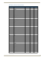
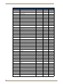
RGB Triplets and Names For Basic 88 Colors ............................................................... 29
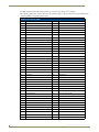
Font Styles and ID Numbers.......................................................................................... 31
Border Styles And Programming Numbers ................................................................... 31
"^" Button Commands ........................................................................................... 34
^ANI.......................................................................................................................................
^APF ......................................................................................................................................
^BAT ......................................................................................................................................
^BAU......................................................................................................................................
^BCB ......................................................................................................................................
^BCF ......................................................................................................................................
^BCT ......................................................................................................................................
^BDO .....................................................................................................................................
^BFB ......................................................................................................................................
^BIM ......................................................................................................................................
^BMC .....................................................................................................................................
^BMF .....................................................................................................................................
^BMI ......................................................................................................................................
^BML......................................................................................................................................
^BMP .....................................................................................................................................
^BNC .....................................................................................................................................
^BNN .....................................................................................................................................
^BNT......................................................................................................................................
^BOP......................................................................................................................................
^BOR......................................................................................................................................
^BPP ......................................................................................................................................
^BRD......................................................................................................................................
^BSF.......................................................................................................................................
^BSM .....................................................................................................................................
^BVL ......................................................................................................................................
^BVN......................................................................................................................................
^BVP ......................................................................................................................................
^BVT ......................................................................................................................................
^BWW....................................................................................................................................
^CPF ......................................................................................................................................
^DPF ......................................................................................................................................
^ENA .....................................................................................................................................
ii
34
34
34
35
35
35
36
36
36
36
37
38
39
40
40
40
40
40
41
41
41
42
42
42
42
42
43
43
43
43
44
44
NXV-300 Modero Virtual Touch Panel
Table of Contents
^FON .....................................................................................................................................
^GDI.......................................................................................................................................
^GIV .......................................................................................................................................
^GLH ......................................................................................................................................
^GLL.......................................................................................................................................
^GRD......................................................................................................................................
^GRU......................................................................................................................................
^GSC ......................................................................................................................................
^GSN......................................................................................................................................
^ICO.......................................................................................................................................
^JSB .......................................................................................................................................
^JSI ........................................................................................................................................
^JST .......................................................................................................................................
^SHO......................................................................................................................................
^TEC.......................................................................................................................................
^TEF .......................................................................................................................................
^TOP ......................................................................................................................................
^TXT.......................................................................................................................................
^UNI.......................................................................................................................................
44
44
45
45
45
45
45
46
46
46
46
47
47
47
47
48
48
48
48
Text Effect Names.................................................................................................. 49
Button Query Commands....................................................................................... 50
?BCB.......................................................................................................................................
?BCF .......................................................................................................................................
?BCT .......................................................................................................................................
?BMP ......................................................................................................................................
?BOP ......................................................................................................................................
?BRD.......................................................................................................................................
?BWW.....................................................................................................................................
?FON ......................................................................................................................................
?ICO .......................................................................................................................................
?JSB........................................................................................................................................
?JSI.........................................................................................................................................
?JST........................................................................................................................................
?TEC .......................................................................................................................................
?TEF .......................................................................................................................................
51
51
52
52
53
53
54
54
55
55
56
56
57
57
Panel Runtime Operations...................................................................................... 58
@AKB .....................................................................................................................................
AKEYB ....................................................................................................................................
?TXT .......................................................................................................................................
AKEYP ....................................................................................................................................
AKEYR ....................................................................................................................................
@AKP......................................................................................................................................
@AKR......................................................................................................................................
@EKP ......................................................................................................................................
PKEYP.....................................................................................................................................
@PKP ......................................................................................................................................
SETUP.....................................................................................................................................
SLEEP .....................................................................................................................................
TPAGEON ..............................................................................................................................
TPAGEOFF .............................................................................................................................
@VKB......................................................................................................................................
WAKE .....................................................................................................................................
NXV-300 Modero Virtual Touch Panel
58
58
58
59
59
59
59
59
59
60
60
60
60
60
60
60
iii
Table of Contents
Input Commands..................................................................................................... 61
^KPS ...................................................................................................................................... 61
^VKS ...................................................................................................................................... 61
Embedded codes .................................................................................................... 62
Panel Setup Commands .......................................................................................... 63
@PWD .................................................................................................................................... 63
^PWD..................................................................................................................................... 63
Dynamic Image Commands..................................................................................... 63
^BBR ......................................................................................................................................
^RAF ......................................................................................................................................
^RFR ......................................................................................................................................
^RMF .....................................................................................................................................
^RSR ......................................................................................................................................
^RAF ......................................................................................................................................
63
63
63
64
64
64
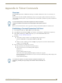
Appendix A: Telnet Commands ........................................................................65
Overview ................................................................................................................ 65
Establishing a Terminal Connection Via Telnet ....................................................... 65
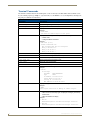
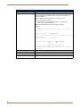
Terminal Commands ............................................................................................... 66
Appendix B - Troubleshooting ..........................................................................71
iv
NXV-300 Modero Virtual Touch Panel
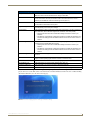
Overview
Overview
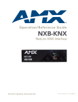
The NetLinx NXV-300 Modero Virtual Touch Panel (FG2263-01) is a small rack-mountable device (similar in size to an
NI-700 NetLinx Controller) that allows users to access a network via any PC or Macintosh computer via Virtual Network
Connection (VNC). Instead of using an actual touch screen to interface with a network, users navigate to the device using
a browser (Internet Explorer, Firefox and Safari for PCs and Firefox and Safari for Macs) and login with a username and
password.
Status LEDs
Reset button
(front)
Ethernet port
(rear)
FIG. 1 NXV-300 Modero Virtual Touch Panel
Product Specifications
NXV-300 (FG2263-01) Specifications
Front Panel
Components:
• Power LED (green): Lights to indicate that the unit has powered up.
• Any state other than on indicates the unit is either not powered, or has not completed boot
up.
• Status LED (green): Lights to show the status of the connection between the NXV-300 and
the Master.
• User Connected LED (red): Lights to indicate a user remotely accessing the device.
• Maximum User LED (yellow): Lights to indicate that the device has the maximum number of
users (3) connected to it.
• Reset Button: Holding reset button for 5 seconds will access the Setup pages. Holding reset
button for 30 seconds will reset the device to factory defaults.
Rear Panel
Connectors:
Ethernet Port - 10/100 Ethernet with PoE. LEDs show communication activity, connection status,
speeds, and mode information:
• SPD (speed) - Yellow LED lights On when the connection speed is 100 Mbps and turns Off
when the speed is 10 Mbps.
• L/A (link/activity) - Green LED lights On when the Ethernet cables are connected and
terminated correctly, and blinks when receiving Ethernet data packets.
Power Requirements:
• Maximum power draw: 2.2 watts
• PoE powered – no local Power Supply needed
• IEEE 802.3af Compliant
Memory:
• 64 Mbytes of RAM
• 256 Mbytes of FLASH
Dimensions (HWD):
1.63" x 5.50" x 4.06" (4.13 cm x 13.97 cm x 10.32 cm)
Weight:
1.40 lbs. (0.64 kg)
Operating
Environment:
• Operating Temperature: 32°F - 104°F (0°C - 40°C)
• Relative Humidity: 5% to 85% non-condensing
• Intended for indoor use only
NXV-300 Modero Virtual Touch Panel
1
Overview
NXV-300 Specifications (Cont.)
Certifications:
• FCC Class B
• CE
• IEC60950
• RoHS
Other AMX
Equipment:
• PS-POE-AF PoE Injector (FG423-80)
• AC-DIN-CS3 DIN Rail Mounting Bracket (FG532-01)
• AC-RK Accessory Rack Kit (FG515)
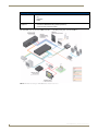
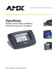
The NXV-300 can be used in most AMX networks as a controlling touch panel, as shown in FIG. 2:
FIG. 2 AMX Network utilizing an NXV-300 Modero Virtual Touch Panel
2
NXV-300 Modero Virtual Touch Panel
Installation
Installation
Wiring and Connections
To avoid any damage to the electronic component, installation must be performed in
an ESD safe environment.
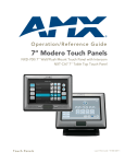
The NXV-300 is installed to the NetLinx Master, and passes NetLinx control commands to the Master via Ethernet 10/
100 cable, as indicated in FIG. 3:
NetLinx Master
Ethernet 10/100
Ethernet Switch
Ethernet 10/100
NXV-300
PoE injector
To Touch Panel
To Laptop
FIG. 3 NXV-300 installation
After you have completed the installation, consult the Setup Pages and Descriptions section on page 5.
Ethernet 10/100 Base-T RJ-45 Wiring Configuration
The table below describes the pinouts, signals, and pairing for the Ethernet 10/100 Base-T connector and cable.
Ethernet Pinouts and Signals
Pin
Signals
Connections
1
TX +
1 --------- 1
Pairing
Color
Diagram
1 --------- 2 White-Orange
2
TX -
2 --------- 2
3
RX +
3 --------- 3
Orange
4
no connection
4 --------- 4
Blue
5
no connection
5 --------- 5
White-Blue
3 --------- 6
White-Green
6
RX -
6 --------- 6
Green
7
no connection
7 --------- 7
White-Brown
8
no connection
8 --------- 8
Brown
PoE (Power Over Ethernet)
The NXV-300 uses CAT5/CAT6 wire via the Ethernet port for PoE power. The maximum power draw for the NXD-300
is 2.2 watts. Use the PS-POE-AF Power over Ethernet Injector (FG423-80) to simplify wiring and installation by
eliminating the need for an AC outlet at each point of installation.
The NXV-300 can be placed up to approximately 330’ (100 meters) from PoE
Injector.
If used with a non PoE-capable Ethernet switch, then an optional PS-POE-AF Power-over-Ethernet (PoE)
power supply is required to provide power to the NXV-300.
If the NXV-300 is used with a PoE-capable Ethernet switch, then no PoE Injectors are required.
NXV-300 Modero Virtual Touch Panel
3
Installation
4
NXV-300 Modero Virtual Touch Panel
Setup Pages and Descriptions
Setup Pages and Descriptions
Overview
NXV-300 devices allow updates and changes to Setup and Protected Setup pages in the same way as any other AMX
touch panel. The main difference is you may make various configuration settings via a web browser on any PC that has
access to the NXV-300 device. Entering the device’s IP address in an enabled browser (Microsoft Internet Explorer,
Mozilla Firefox and Apple Safari for PCs and Firefox and Safari for Macintoshes) allows the device to be accessed in
that browser. Once contact is established, and a username and password entered, the Setup pages may be reached and
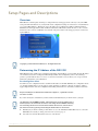
updated (FIG. 4).
FIG. 4 NXV-300 Main Setup Page
Copyright (c) 2009 GoAhead Software, Inc. All Rights Reserved.
Determining the IP Address of the NXV-300
NXV-300 units feature a built-in zero-configuration networking client that allows you to determine the unit’s IP address
via a client that uses the Zero Configuration Networking Standard. Zero Configuration (or Zeroconf) technology
provides a general method to discover services on a local area network. In essence, it allows you to set up a network
without any configuration, as described below.
Zero-Configuration Client
You will need a zero-configuration client to determine the IP address of the NXV-300. Many zero-configuration clients
are currently available. However, for the purposes of this document, we will refer to Bonjour for Windows, which is
Apple's implementation of the Zero Configuration Networking Standard. It is free and widely available for download.
Bonjour and Bonjour for Windows are trademarks of Apple Inc., registered in the U.S.
and other countries.
If you don’t already have it installed on your PC, download and install Bonjour for Windows before you begin.
The NXV-300 is set to DHCP by default. If the device does not get an address from a
DHCP request, it will set itself to 169.254.2.2 and change the IP to Static. Rebooting
and connecting the device to a known DHCP network will not work, and the device
will need to be reset by pressing and holding the Reset button for 30 seconds.
1. With Bonjour for Windows running on a PC that has access to the LAN that the NXV-300 resides on, connect the
NXV-300 to the network (see Wiring and Connections section on page 3).
2. Select the device from the Bonjour list of devices on the browser.
NXV-300 Modero Virtual Touch Panel
5
Setup Pages and Descriptions
3. The browser will bring up the main touch panel page. To open the Setup pages, press and hold the Reset Button on
the front of the device for 5 seconds.
4. Access the Protected Setup pages, using your password if necessary. The unit’s IP Address is displayed in the
System Settings - IP page in the Protected Setup pages.
At this point, you can assign a static IP Address if necessary.
If no DHCP server can be detected by the device, then the device will default to the IP address 169.254.2.2 and change
the IP setting to Static. To connect to a DHCP server in the future, the device must be reset by holding and pressing the
Reset button on the front of the device for 30 seconds.
Current IP Address
FIG. 5 System Settings - IP page and IP address
Bonjour for Windows operates as a plug-in for Microsoft Internet Explorer, and is
displayed in the IE Explorer Bar. If you have installed Bonjour for Windows, but don’t
see the Bonjour toolbar icon, you may need to "unlock" and expand the toolbars to
see it.
Accessing the NXV-300
From any computer or Netbook that has access to the LAN that the NXV-300 resides on, open a web browser and type
the IP address of the target NXV-300 unit in the Address Bar.
The default state of the NXV-300 allows anyone with the device IP address to access
the device, up to the maximum of three users at a time. This access status may be
changed by setting a password through the G4 Web Control page, which then
prompts the user to enter the password when accessing the device.
6
NXV-300 Modero Virtual Touch Panel
Setup Pages and Descriptions
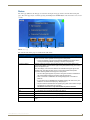
Status
The Status page (FIG. 6) is the first page viewed when entering the Setup page interface from the main touch panel
pages. The Status page may be reached by pressing and holding down the Reset button on the front of the device for six
seconds.
Display
Current time
Info
Date
Protected Setup
FIG. 6 Status Page
The elements of the Status page are described in the table below:
Status Page Elements
Connection Status icon:
This visual display of the connection status allows the user to have a current update of the
panel’s connection status regardless of what page is currently active.
• A Lock only appears on the icon if the panel has established a connection with a
currently secured target Master (requiring a username and password).
Connection Status:
Displays whether the panel is communicating externally, the encryption status of the
communicating Master, what connection type is being used (Ethernet only), and of what
System the panel is a part.
This visual display of the connection status is also reflected at the upper-right of each
firmware page. This allows the user to have a current visual update of the panel’s
connection status regardless of what page is currently active.
• The word "Encrypted" appears only when an encrypted connection is established
with a target Master. Otherwise, the status reads "No Encryption".
• When a connection is established, the message displayed is: "Connected via
Ethernet ".
• If no connection can be established by the Modero panel, it will continue to try and
establish a connection while displaying: "Attempting via...".
• The panel must be rebooted before incorporating any panel communication changes
and detecting any active Ethernet connections.
The Ethernet connection is only detected after the panel is rebooted.
Display:
• This button opens the Display page (page 8).
Info:
• This button opens the Panel Information page (page 9).
Protected Setup:
• This button opens the Protected Setup page (page 12).
Current Time/Date
• The time and date in these fields are provided by the Master.
Exit:
NXV-300 Modero Virtual Touch Panel
Returns to the Main touch panel page. In this case, the previous page is the default Main
page.
7
Setup Pages and Descriptions
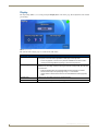
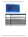
Display
The Display Page (FIG. 7), accessed by pressing the Display button on the Status page, allows adjustment of the default
panel settings.
FIG. 7 Display Page
The elements of the Display page are described in the table below:
Display Page Elements
Connection Status icon:
This visual display of the connection status allows the user to have a current visual update
of the panel’s connection status regardless of what page is currently active.
• A Lock only appears on the icon if the panel has established a connection with a
currently secured target Master (requiring a username and password).
Inactivity Page Wait Time:
Sets the number of minutes of inactivity before the panel automatically flips to a preselected touch panel page. When the device goes into this inactivity mode, the LCD does
not power down.
• Press the UP/DN buttons to increase/decrease the time the panel can remain
inactive before it flips to the preset page. Range = 0 - 240 minutes.
• Use this button to set the timeout value to zero and disable the inactivity page flip
mode.
8
Inactivity Page:
Lists the touch panel page used for the Inactivity page flip.
Back:
Returns to the previously active touch panel page.
NXV-300 Modero Virtual Touch Panel
Setup Pages and Descriptions
Panel Information
The Project Information page displays the TPDesign4 (TPD4) project file properties currently loaded on the selected
Modero panel (FIG. 8). Refer to the TPDesign4 Touch Panel Program instruction manual for more specific information
on uploading TPDesign4 files to a panel. Select between the Info, Config, File, and Project tabs to view the appropriate
information.
Panel Information - Info Tab
FIG. 8 Panel Information Page - Info Tab
The elements of the Panel Information page Info tab are described in the table below:
Panel Information Page - Info Tab Elements
Connection Status icon:
This visual display of the connection status allows the user to have a current visual update
of the panel’s connection status, regardless of what page is currently active.
• A Lock only appears on the icon if the panel has established a connection with a
currently secured target Master requiring a username and password.
Panel Type:
Displays the model of the Modero panel being used.
Firmware Version:
Displays the G4 firmware version being used by the panel.
Serial Number:
Displays the specific serial number value assigned to the panel.
Setup Pages:
Displays the type and version of the Setup pages being used by the panel.
Panel Start Time:
Displays the last time the panel booted.
• Verify that the panel has the latest version from www.amx.com.
Screen Width:
Displays the pixel width being used to display the incoming signal on the Modero panel.
Screen Height:
Displays the pixel height being used to display the incoming signal on the Modero panel.
Screen Refresh:
Displays the refresh rate applied to the incoming signal from the panel. Default rate is 60.
Screen Rotation:
Displays the degree of rotation applied to the on-screen image.
File System:
Displays the amount of Flash memory available on the Modero panel.
RAM:
Displays the available RAM (or Extended Memory module) on the Modero panel.
Back:
Returns to the previously active touch panel page.
NXV-300 Modero Virtual Touch Panel
9
Setup Pages and Descriptions
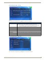
Panel Information Page - Config Tab
FIG. 9 Panel Information Page - Config Tab
The elements of the Panel Information page Config tab are described in the table below:
Project Information Page - Config Tab Elements
Connection Status icon:
This visual display of the connection status allows the user to have a current visual update
of the panel’s connection status regardless of what page is
currently active.
• A Lock only appears on the icon if the panel has established a connection with a
currently secured target Master (requiring a username and password).
Power Up Page:
Displays the first touch panel page assigned for display after the device is powered-up.
• This information is taken from the TPD4 project file.
Most projects begin with a Main page.
Start-Up String:
10
Displays the start-up string.
Wake-Up String:
Displays the wake up string used after an activation from a timeout.
Sleep String:
Displays the sleep string used during a panel’s sleep mode.
Setup Port:
Displays the setup port information/value being used by the panel.
High Port:
Displays the high port (port count) value for the panel.
High Address:
Displays the high address (address count) value for the panel.
High Channel:
Displays the high channel (channel count) value for the panel.
High Level:
Displays the high level (level count) value being used by the panel.
Back:
Returns to the previously active touch panel page.
NXV-300 Modero Virtual Touch Panel
Setup Pages and Descriptions
Panel Information Page - File Tab
FIG. 10 Panel Information Page - File Tab
The elements of the Panel Information page File tab are described in the table below:
Project Information Page - File Tab Elements
Connection Status icon:
This visual display of the connection status allows the user to have a current visual update
of the panel’s connection status regardless of what page is currently active.
• A Lock only appears on the icon if the panel has established a connection with a
currently secured target Master (requiring a username and password).
File Name:
Displays the name of the TPDesign4 project file downloaded to the panel.
File Revision:
Displays the revision number of the file.
Last Save:
Displays the last date the project was saved.
Creation Date:
Displays the project creation date.
Revision Date:
Displays the last revision date for the project.
Build Number:
Displays the build number information of the TPD4 software used to create the project file.
Blink Rate:
Displays the feedback blink rate (by 10th of a second).
Back:
Returns to the previously active touch panel page.
File Information Page - Project Tab
FIG. 11 Panel Information Page - Project Tab
The elements of the Panel Information page Project tab are described in the table below:
NXV-300 Modero Virtual Touch Panel
11
Setup Pages and Descriptions
Project Information Page - File Tab Elements
Connection Status icon:
This visual display of the connection status allows the user to have a current visual update
of the panel’s connection status regardless of what page is currently active.
• A Lock only appears on the icon if the panel has established a connection with a
currently secured target Master (requiring a username and password).
Designer ID:
Displays the designer information for the panel.
Dealer ID:
Displays the dealer ID number (unique to every dealer and entered in TPD4).
Job Name:
Displays the job name.
Sales Order:
Displays the sales order information.
Purchase Order:
Displays the purchase order information.
Job Comments:
Displays any comments associated to the job. These comments are taken from the TPD4
project file.
Back:
Returns to the previously active touch panel page.
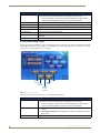
Protected Setup Page
The Protected Setup page (FIG. 12) centers around the properties used by the panel for proper communication with the
NetLinx Master. Enter the factory default password (1988) into the password keypad (please refer to the Password Page
on page 18 for more information) to access this page.
Password
System
Settings
Connection
Panel
Utility
Statistics
G4 Web
Control
Settings
FIG. 12 Protected Setup Page
The elements of the Protected Setup page are described in the table below:
Protected Setup Page Elements
Connection Status icon:
This visual display of the connection status allows the user to have a current visual update
of the panel’s connection status regardless of what page is currently active.
• A Lock only appears on the icon if the panel has established a connection with a
currently secured target Master, requiring a username and password.
Device Information:
• Device Number: Opens a keypad that is used to set and display the current device
number.
• Device/Bonjour Name: Opens a keypad that is used to set and display the current
device name.
Reboot:
12
Press this button to restart the panel after saving any changes.
NXV-300 Modero Virtual Touch Panel
Setup Pages and Descriptions
Protected Setup Page Elements (Cont.)
Bonjour:
Press this button to enable or disable broadcast of any Zero Config information.
Note: The device must be rebooted for the change to take effect.
Function Show:
Press this button to enable the display of the channel port and channel code in the top left
corner of the button, the level port and level code in the bottom left corner, and the
address port and address code in the bottom right corner (FIG. 14).
Telnet:
Press this button to enable or disable the telnet server on the panel. This feature focuses
on direct telnet communication to the panel.
Page Tracking:
Press this button for the touch panel sends page data back to the NetLinx Master, or vice
versa depending on the touch panel settings.
Reset Settings:
Press this button to wipe out all current configuration parameters on the touch panel (such
as IP Addresses, Device Number assignments, Passwords, and other presets).
• Pressing this button launches a Confirmation dialog which asks to confirm your
selection.
• This dialog is configured with a delay timer that does not enable the YES button for 5
seconds. This delay provides an additional amount of time for the user to confirm a
decision.
Remove Pages:
Press this button to remove all current TPD4 touch panel pages currently on the panel
(including the pre-installed AMX Demo pages).
• Pressing this button launches a Confirmation dialog which asks to confirm your
selection.
• This dialog is configured with a delay timer that does not enable the YES button for 5
seconds. This delay provides an additional amount of time for the user to confirm a
decision.
System Settings icon:
Press this button to configure communication settings between the NetLinx Master and
the panel.
G4 Web Control icon:
Press this button to allow for password protection. This controls access to the NXV-300
pages, as well as specifying the maximum number of connected users.
Passwords icon:
Press this button to access the Passwords Page (page 18).
Panel Statistics icon:
Press this button to access the Panel Statistics Page (page 19).
Connection Utility icon:
Press this button to access the Connection Utility Page (page 21).
Back:
Saves the changes and returns to the previously active touch panel page.
Any use of the Reset Settings or Remove Pages buttons opens up the Confirmation Dialog window. The Yes button is
grayed out for ten seconds while a timer reads down between it and the No button, and then becomes enabled. Clicking
either button will return you to the Protected Setup page.
FIG. 13 Protected Setup page-System Settings confirmation dialog
NXV-300 Modero Virtual Touch Panel
13
Setup Pages and Descriptions
Pressing the Function Show button once displays the function information on each button and slider in the Setup and
Protected Setup pages (FIG. 13). Press the button again to hide the function information.
FIG. 14 Button/slider Function Show example
Protected Settings Page Icons
The interface for the Protected Settings page includes buttons featuring icons instead of text. These button icons include:
Password
System
Settings
Connection
Panel
Utility
Statistics
G4 Web
Control
Settings
FIG. 15 Protected Settings page button icons
System Settings (page 15): Press this button to configure communication settings between the NetLinx
Master and the panel.
G4 Web Control (page 17): Press this button to allow for password protection. This controls access to the
NXV-300 pages, as well as specifying the maximum number of connected users via a Web-enabled computer
or Netbook.
Passwords (page 18): Press this button to access the Passwords Page.
Panel Statistics (page 19): Press this button to access the Panel Statistics Page.
Connection Utility (page 21): Press this button to access the Connection Utility Page.
14
NXV-300 Modero Virtual Touch Panel
Setup Pages and Descriptions
System Settings Page
The System Settings page (FIG. 16) sets Primary and Secondary DNS Address information with its corresponding IP
communication parameters, sets NetLinx Master communication settings, and reads the device number assigned to the
Modero panel. Select between the IP and Master tabs to view the appropriate information.
Changes made on any tab of this page are not saved until the panel is rebooted.
System Settings Page - IP Tab
The IP tab is the default tab on the System Settings page. This tab contains the main IP and MAC address information for
the panel.
FIG. 16 System Settings Page - IP Tab
The elements of the System Settings page - IP Tab are as follows:
System Settings Page - IP Tab Elements
Connection Status icon:
This visual display of the connection status allows the user to have a current visual update
of the panel’s connection status, regardless of what page is currently active.
• A Lock only appears on the icon if the panel has established a connection with a
currently secured target Master, which requires a username and password.
DHCP/Static
Sets the panel to either DHCP or Static communication modes.
• DHCP (Dynamic Host Configuration Protocol) assigns IP Addresses from client
stations logging onto a TCP/IP network via a DHCP server.
• Static IP is a permanent IP Address that is assigned to a node in a TCP/IP network.
IP Address
Sets the IP Address assigned to the panel.
Subnet Mask
Sets a subnetwork address to the panel.
• Subnetwork mask is the technique used by the IP protocol to filter messages into a
particular network segment (Subnet).
Gateway
Sets a gateway value to the panel.
• Gateway is a computer that either performs protocol conversion between different
types of networks/applications or acts as a go-between two or more networks that
use the same protocols.
Host Name
Sets the host name of the panel.
Primary DNS
Sets the address of the primary DNS server used for host name lookups.
• DNS (Domain Name System) is software that lets users locate computers on a local
network or the Internet (TCP/IP network) by host and domain. The DNS server
maintains a database of host names for its domain and their corresponding IP
Addresses.
Secondary DNS
NXV-300 Modero Virtual Touch Panel
Sets a secondary DNS value to the panel.
15
Setup Pages and Descriptions
System Settings Page - IP Tab Elements (Cont.)
Domain
Sets the unique name on the Internet to the panel for DNS look-up.
• The panel belongs to the DNS domain.
Ethernet Mode
Sets the speed of the Ethernet connection to the panel.
• Choices are: Auto, 10 Half Duplex, 10 Full Duplex, 100 Half Duplex, or
100 Full Duplex.
MAC Address
Displays a read-only field that is factory set by AMX for the built-in Ethernet interface.
Save & Reboot:
Saves any changes and reboots the device in order to implement those changes.
Cancel:
Returns to the previous page without saving any changes.
System Settings - Master Tab
The Master tab of the System Settings page contains the necessary information for connecting to the network Master.
FIG. 17 System Settings page - Master Tab
The elements of the System Settings page - Master Tab are as follows:
System Settings Page - Master Tab Elements
Connection Status
icon:
This visual display of the connection status allows the user to have a current visual update of the
panel’s connection status, regardless of what page is currently active.
• A Lock only appears on the icon if the panel has established a connection with a currently
secured target Master, which requires a username and password.
Type:
Sets the NetLinx Master to communicate with the panel via Ethernet. This is based on the cable
connection from the rear.
• Ethernet is a CAT-5 cable (10/100Base T terminated in an RJ-45 connector) used to network
computers together and is used in most LAN (local area networks).
Mode:
Cycles between the different connection modes (URL, Listen, NDP(UDP), URL(UDP), and Auto):
• Auto - In this mode, enter the System Number and a username/password (if applicable).
This mode is used when both the panel and the NetLinx Master are on the same Subnet and
the Master has its UDP feature enabled. The Master IP/URL field is read-only because the
panel obtains this information from the communicating Master.
• URL - In this mode, enter the Master IP/URL, Master Port Number, and username/password
(if used) on the Master. The System Number field is read-only.
• Listen - In this mode, add the Modero panel address into the URL List in NetLinx Studio and
set the connection mode to Listen. This mode allows the Modero touch panel to "listen" for
the Master’s communication signals. The System Number and Master IP/URL fields are
read-only.
• NDP(UDP) - This mode uses UDP instead of TCP to access the device. The System
Number and Master IP/URL fields are read-only.
• URL(UDP) - This mode uses UDP instead of TCP to access the device. The System number
field is read-only.
16
NXV-300 Modero Virtual Touch Panel
Setup Pages and Descriptions
System Settings Page - Master Tab Elements
System Number:
Allows you to enter a system number. Default value is 0 (zero).
Master IP/URL:
Sets the Master IP or URL of the NetLinx Master. This field is only enabled when selecting either
the URL or the URL(UDP) Modes.
Master Port Number:
Enters the port number used with the NetLinx Master.
• Default value is 1319.
Username/Password: If the target Master has been previously secured, enter the alphanumeric string (into each field)
assigned to a pre-configured user profile on the Master. This profile should have the pre-defined
level of access/configuration rights.
NDP Name:
The Nexus Delivery Protocol name for the device. The NDP name allows use of a master web
interface, NetLinx Studio 2.4 or commands to bind the device with NetLinx masters.
Save & Reboot:
Saves any changes and reboots the device in order to implement those changes.
Cancel:
Returns to the previous page without saving any changes.
G4 Web Control Page
The G4 Web Control page (FIG. 18) centers around enabling and disabling both the display and control of your panel via
the Web. An external computer or Netbook running a VNC client such as Bonjour, installed during the initial
communication to the G4 panel, makes this possible.
FIG. 18 G4 Web Control Settings page
The NXV-300 supports the open standard Virtual Network Computing (VNC) interface. This device contains a VNC
server that allows it to accept a connection from any other device running a VNC client. Once a connection is established
to that target device, the client can control the device remotely. The elements of the G4 Web Control Settings page are as
follows:
G4 Web Control Settings Page Elements
Connection Status icon:
This visual display of the connection status allows the user to have a current visual update
of the panel’s connection status regardless of what page is
currently active.
• A Lock only appears on the icon if the panel has established a connection with a
currently secured target Master (requiring a username and password).
G4 Web Control Settings:
Enabled
Timeout:
Sets the remote control values for the touch panel and contains:
• The Enabled button activates the G4 Web Control feature on the panel and allows
an external PC running a VNC client to access the panel after the remaining fields
are configured. This button is always on.
Sets the length of time (in minutes) the panel can remain idle (no cursor
movements) before the session is closed and the user is disconnected.
• Minimum value = 0 minutes (panel never times-out)
• Maximum value = 240 minutes (panel times-out after 240 minutes/4hours)
Network Interface
Displays the detected method of communication to the web:
• Wired is used when a direct Ethernet connection is being used for communication to
the web. This is the only setting.
NXV-300 Modero Virtual Touch Panel
17
Setup Pages and Descriptions
G4 Web Control Page Elements (Cont.)
Control Name
The Control Name is the same name as the Device Name set in the Protected Setup
Pages. The Control Name cannot be changed. This Web Control tab displays a G4 icon
alongside the link to the Web Control Name given to this panel (FIG. 18).
Control Password
Allows entry of the G4 Authentication session password associated for VNC web access
of this panel.
Control Port
Allows entry of the VNC Web Server’s port value.
Max Connects
This field displays the maximum number of users that can be connected simultaneously to
the target panel via the Web. Click on the field to change the maximum number.
Connect Count
This read-only field displays the current number of users connected to the target panel via
the Web. This value cannot exceed the Maximum number field.
Back:
Saves the changes and returns to the previously active touch panel page.
• Default value is 5900.
• Default value is 1.
Password Page
The options on the Password page (FIG. 19) allow you to assign the passwords required for users to access the Protected
Setup page.
FIG. 19 Password page
Features on this page include:
Password Page
Connection Status icon:
The icon in the upper-right corner of each Setup page shows online/offline state of the
panel to the master.
• Bright red - disconnected
• Bright green - connected. Blinks when a blink message is received to dark green
every 5 seconds for half a second then go back to bright green.
• Bright yellow - panel missed a blink message from the master. It will remain yellow
for 3 missed blink messages and then turn red. It will return to green when a blink
message is received.
Note: a Lock appears on the icon if the panel is connected to a secured NetLinx Master.
In Panel Password Change:
Accesses the alphanumeric values associated to particular password sets.
• The PASSWORD 1, 2, 3, 4 and 5 (protected) buttons open a keyboard to enter
alphanumeric values associated to the selected password group.
Note: Clearing Password #5 removes the need to enter a password before accessing the
Protected Setup page.
Back:
18
Saves all changes and returns to the previous page.
NXV-300 Modero Virtual Touch Panel
Setup Pages and Descriptions
Panel Statistics Page
The options on the Panel Statistics page allow you to track the connection status for the panel. The Panel Statistics page
tracks ICSP messages and Blink messages statistics (FIG. 20). Select between the ICSP and Blinks tabs to view the
appropriate information.
Panel Statistics - ICSP Tab
FIG. 20 Panel Statistics Page - ICSP Tab
The ICSP Tab tracks messages between the master and the touch panel, as ICSP is the protocol they use to communicate
with each other. Features on this tab are as follows:
Panel Statistics Page - ICSP Tab Elements
Connection Status icon:
The icon in the upper-right corner of each Setup page shows online/offline state of the panel
to the master.
• Bright red - disconnected
• Bright green - connected. Blinks when a blink message is received to dark green every 5
seconds for half a second then go back to bright green.
• Bright yellow - panel missed a blink message from the master. It will remain yellow for 3
missed blink messages and then turn red. It will return to green when a blink message is
received.
Note: a Lock appears on the icon if the panel is connected to a secured NetLinx Master.
Total
• Received - The total ICSP messages received by the panel.
• Processed - The total ICSP messages processed by the panel.
• Dropped - The total ICSP messages dropped by the panel.
Last 15 Minutes
• Received - The total ICSP messages received by the panel in the last 15 minutes.
• Processed - The total ICSP messages processed by the panel in the last 15 minutes.
• Dropped - The total ICSP messages dropped by the panel in the last 15 minutes.
Clear
This button resets all panel statistics on this page.
Refresh
This button refreshes all panel statistics to the values recorded at the moment the button is
pressed.
Back:
Returns to the previous page.
NXV-300 Modero Virtual Touch Panel
19
Setup Pages and Descriptions
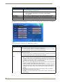
Panel Statistics - Blinks Tab
FIG. 21 Panel Statistics Page - Blinks Tab
The Blinks Tab tracks blinks, which are messages sent by the master once every 5 seconds to all connected devices.
Features on this tab are as follows:
Panel Statistics Page - Blinks Tab Elements
Connection Status icon:
The icon in the upper-right corner of each Setup page shows online/offline state of the panel
to the master.
• Bright red - disconnected
• Bright green - connected. Blinks when a blink message is received to dark green every
5 seconds for half a second then go back to bright green.
• Bright yellow - panel missed a blink message from the master. It will remain yellow for 3
missed blink messages and then turn red. It will return to green when a blink message is
received.
Note: a Lock appears on the icon if the panel is connected to a secured NetLinx Master.
Total:
• Received - The total Blink messages received by the panel.
• Missed - The total Blink messages missed by the panel.
Last 15 Minutes:
• Received - The total Blink messages received by the panel in the last 15 minutes.
• Missed - The total Blink messages missed by the panel in the last 15 minutes.
20
Clear:
Pressing this button clears all fields on this page.
Refresh:
Pressing this button refreshes all data in the fields on this page.
Back:
Returns to the previous page.
NXV-300 Modero Virtual Touch Panel
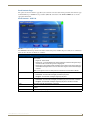
Setup Pages and Descriptions
Connection Utility
The Connection Utility Page (FIG. 22) opens directly over the Protected Setup Page. Use this page to access the
connection information for the panel, such as the panel IP address.
FIG. 22 Connection Utility Page
Features on this page are as follows:
Connection Utility Page
Connection Status icon:
The icon in the upper-right corner of the utility provides a constant visual indication of
current connection status.
A message is sent to the master once per second and expects a response.
• If it is received, the button stays green.
• If it is missed, the button goes yellow.
• After three misses (3 seconds), it will go red until a response from the master is
received, and then it will be green again.
Connection Information
Master IP
The IP Address for the connected master.
Panel IP
The IP Address for the panel.
Connection Statistics
Messages Sent
The number of messages sent from the panel to the master.
Responses Received
The number of responses the panel has received from the master.
Responses Missed
The number of expected responses from the master to the panel missed.
Back:
NXV-300 Modero Virtual Touch Panel
Returns to the Protected Settings Page.
21
Setup Pages and Descriptions
22
NXV-300 Modero Virtual Touch Panel
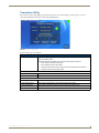
NetLinx Programming
NetLinx Programming
The NXV-300 may be programmed, using the commands in this section, to perform a wide variety of operations using
Send_Commands and variable text commands.
A device must first be defined in the NetLinx programming language with values for the Device: Port: System (in
all programming examples - Panel is used in place of these values and represents all Modero panels).
Verify that you are using the latest NetLinx Master and Modero firmware, and verify
that you are using the latest version of NetLinx Studio and TPD4.
Button Assignments
• Button Channel Range: 1 - 4000 Button push and Feedback (per address port)
• Button Variable Text range: 1 - 4000 (per address port)
• Button States Range: 1 - 256 (0 = All states, for General buttons 1 = Off state and 2 = On state).
• Level Range: 1 - 600 (Default level value 0 - 255, can be set up to 1 - 65535)
• Address port Range: 1 - 100
These button assignments can only be adjusted in TPD4 and not on the panels
themselves.
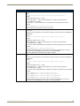
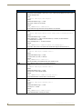
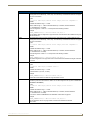
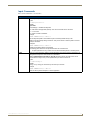
Page Commands
These Page Commands are used in NetLinx Programming Language and are case insensitive.
Page Commands
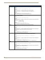
@APG
Add the popup page to a group if it does not already exist. If the new popup is added to a group which
has a popup displayed on the current page along with the new pop-up, the displayed popup will be
hidden and the new popup will be displayed.
Syntax:
"'@APG-<popup page name>;<popup group name>'"
Variable:
popup page name = 1 - 50 ASCII characters. Name of the popup page.
popup group name = 1 - 50 ASCII characters. Name of the popup group.
Example:
SEND_COMMAND Panel,"'@APG-Popup1;Group1'"
Adds the popup page ’Popup1’ to the popup group ’Group1’.
@CPG
Clear all popup pages from specified popup group.
Syntax:
"'@CPG-<popup group name>'"
Variable:
popup group name = 1 - 50 ASCII characters. Name of the popup group.
Example:
SEND_COMMAND Panel,"'@CPG-Group1'"
Clears all popup pages from the popup group ’Group1’.
NXV-300 Modero Virtual Touch Panel
23
NetLinx Programming
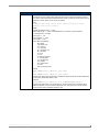
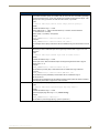
Page Commands (Cont.)
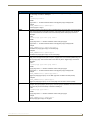
@DPG
Delete a specific popup page from specified popup group if it exists.
Syntax:
"'@DPG-<popup page name>;<popup group name>'"
Variable:
popup page name = 1 - 50 ASCII characters. Name of the popup page.
popup group name = 1 - 50 ASCII characters. Name of the popup group.
Example:
SEND_COMMAND Panel,"'@DPG-Popup1;Group1'"
Deletes the popup page ’Popup1’ from the popup group ’Group1’.
@PDR
Set the popup location reset flag. If the flag is set, the popup will return to its default location on show
instead of its last drag location.
Syntax:
"'@PDR-<popup page name>;<reset flag>'"
Variable:
popup page name = 1 - 50 ASCII characters. Name of the page the popup is displayed On.
reset flag = 1 = Enable reset flag
0 = Disable reset flag
Example:
SEND_COMMAND Panel,"'@PDR-Popup1;1'"
Popup1 will return to its default location when turned On.
@PHE
Set the hide effect for the specified popup page to the named hide effect.
Syntax:
"'@PHE-<popup page name>;<hide effect name>'"
Variable:
popup page name = 1 - 50 ASCII characters. Name of the page the popup is displayed On.
hide effect name = Refers to the popup effect names being used.
Example:
SEND_COMMAND Panel,"'@PHE-Popup1;Slide to Left'"
Sets the Popup1 hide effect name to ’Slide to Left’.
@PHP
Set the hide effect position. Only 1 coordinate is ever needed for an effect; however, the command
will specify both. This command sets the location at which the effect will end at.
Syntax:
"'@PHP-<popup page name>;<x coordinate>,<y coordinate>'"
Variable:
popup page name = 1 - 50 ASCII characters. Name of the page the popup is displayed On.
Example:
SEND_COMMAND Panel,"'@PHP-Popup1;75,0'"
Sets the Popup1 hide effect x-coordinate value to 75 and the y-coordinate value to 0.
@PHT
Set the hide effect time for the specified popup page.
Syntax:
"'@PHT-<popup page name>;<hide effect time>'"
Variable:
popup page name = 1 - 50 ASCII characters. Name of the page the popup is displayed On.
hide effect time = Given in 1/10ths of a second.
Example:
SEND_COMMAND Panel,"'@PHT-Popup1;50'"
Sets the Popup1 hide effect time to 5 seconds.
24
NXV-300 Modero Virtual Touch Panel
NetLinx Programming
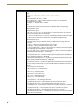
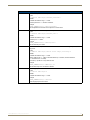
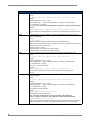
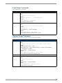
Page Commands (Cont.)
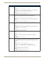
@PPA
Close all popups on a specified page. If the page name is empty, the current page is used. Same as
the ’Clear Page’ command in TPDesign4.
Syntax:
"'@PPA-<page name>'"
Variable:
page name = 1 - 50 ASCII characters. Name of the page the popup is displayed On.
Example:
SEND_COMMAND Panel,"'@PPA-Page1'"
Close all popups on Page1.
@PPF
Deactivate a specific popup page on either a specified page or the current page. If the page name is
empty, the current page is used (see example 2). If the popup page is part of a group, the whole
group is deactivated. This command works in the same way as the ’Hide Popup’ command in
TPDesign4.
Syntax:
"'@PPF-<popup page name>;<page name>'"
Variable:
popup page name = 1 - 50 ASCII characters. Name of the popup page.
page name = 1 - 50 ASCII characters. Name of the page the popup is displayed On.
Example:
SEND_COMMAND Panel,"'@PPF-Popup1;Main'"
Deactivates the popup page ’Popup1’ on the Main page.
Example 2:
SEND_COMMAND Panel,"'@PPF-Popup1'"
Deactivates the popup page ’Popup1’ on the current page.
@PPG
Toggle a specific popup page on either a specified page or the current page. If the page name is
empty, the current page is used (see example 2). Toggling refers to the activating/deactivating (On/
Off) of a popup page. This command works in the same way as the ’Toggle Popup’ command in
TPDesign4.
Syntax:
"'@PPG-<popup page name>;<page name>'"
Variable:
popup page name = 1 - 50 ASCII characters. Name of the popup page.
page name = 1 - 50 ASCII characters. Name of the page the popup is displayed On.
Example:
SEND_COMMAND Panel,"'@PPG-Popup1;Main'"
Toggles the popup page ’Popup1’ on the ’Main’ page from one state to another (On/Off).
Example 2:
SEND_COMMAND Panel,"'@PPG-Popup1'"
Toggles the popup page ’Popup1’ on the current page from one state to another (On/Off).
@PPK
Kill a specific popup page from all pages. Kill refers to the deactivating (Off) of a popup window from
all pages. If the pop-up page is part of a group, the whole group is deactivated. This command works
in the same way as the 'Clear Group' command in TPDesign 4.
Syntax:
"'@PPK-<popup page name>'"
Variable:
popup page name = 1 - 50 ASCII characters. Name of the popup page.
Example:
SEND_COMMAND Panel,"'@PPK-Popup1'"
Kills the popup page ’Popup1’ on all pages.
NXV-300 Modero Virtual Touch Panel
25
NetLinx Programming
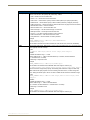
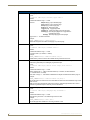
Page Commands (Cont.)
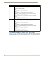
@PPM
Set the modality of a specific popup page to Modal or Non Modal. A Modal popup page, when active,
only allows use of the buttons and features on that popup page. All other buttons on the panel page
are inactivated.
Syntax:
"'@PPM-<popup page name>;<mode>'"
Variable:
popup page name = 1 - 50 ASCII characters. Name of the popup page.
mode = NONMODAL converts a previously Modal popup page to a Non Modal.
MODAL converts a previously Non Modal popup page to Modal.
modal = 1 and non-modal = 0
Example:
SEND_COMMAND Panel,"'@PPM-Popup1;Modal'"
Sets the popup page ’Popup1’ to Modal.
SEND_COMMAND Panel,"'@PPM-Popup1;1'"
Sets the popup page ’Popup1’ to Modal.
@PPN
Activate a specific popup page to launch on either a specified page or the current page. If the page
name is empty, the current page is used (see example 2). If the popup page is already on, do not redraw it. This command works in the same way as the ’Show Popup’ command in TPDesign4.
Syntax:
"'@PPN-<popup page name>;<page name>'"
Variable:
popup page name = 1 - 50 ASCII characters. Name of the popup page.
page name = 1 - 50 ASCII characters. Name of the page the popup is displayed On.
Example:
SEND_COMMAND Panel,"'@PPN-Popup1;Main'"
Activates ’Popup1’ on the ’Main’ page.
Example 2:
SEND_COMMAND Panel,"'@PPN-Popup1'"
Activates the popup page ’Popup1’ on the current page.
@PPT
Set a specific popup page to timeout within a specified time. If timeout is empty, the popup page will
clear the timeout.
Syntax:
"'@PPT-<popup page name>;<timeout>'"
Variable:
popup page name = 1 - 50 ASCII characters. Name of the popup page.
timeout = Timeout duration in 1/10ths of a second.
Example:
SEND_COMMAND Panel,"'@PPT-Popup1;30'"
Sets the popup page ’Popup1’ to timeout within 3 seconds.
@PPX
Close all popups on all pages. This command works in the same way as the 'Clear All' command in
TPDesign 4.
Syntax:
"'@PPX'"
Example:
SEND_COMMAND Panel,"'@PPX'"
Close all popups on all pages.
26
NXV-300 Modero Virtual Touch Panel
NetLinx Programming
Page Commands (Cont.)
@PSE
Set the show effect for the specified popup page to the named show effect.
Syntax:
"'@PSE-<popup page name>;<show effect name>'"
Variable:
popup page name = 1 - 50 ASCII characters. Name of the page the popup is displayed On.
show effect name = Refers to the popup effect name being used.
Example:
SEND_COMMAND Panel,"'@PSE-Popup1;Slide from Left'"
Sets the Popup1 show effect name to ’Slide from Left’.
@PSP
Set the show effect position. Only 1 coordinate is ever needed for an effect; however, the command
will specify both. This command sets the location at which the effect will begin at.
Syntax:
"'@PSP-<popup page name>;<x coordinate>,<y coordinate>'"
Variable:
popup page name = 1 - 50 ASCII characters. Name of the page the popup is displayed On.
Example:
SEND_COMMAND Panel,"'@PSP-Popup1;100,0'"
Sets the Popup1 show effect x-coordinate value to 100 and the y-coordinate value to 0.
@PST
Set the show effect time for the specified popup page.
Syntax:
"'@PST-<popup page name>;<show effect time>'"
Variable:
popup page name = 1 - 50 ASCII characters. Name of the page the popup is displayed On.
show effect time = Given in 1/10ths of a second.
Example:
SEND_COMMAND Panel,"'@PST-Popup1;50'"
Sets the Popup1 show effect time to 5 seconds.
PAGE
Flips to a page with a specified page name. If the page is currently active, it will not redraw the page.
Syntax:
"'PAGE-<page name>'"
Variable:
page name = 1 - 50 ASCII characters. Name of the page the popup is displayed On.
Example:
SEND_COMMAND Panel,"'PAGE-Page1'"
Flips to page1.
PPOF
Deactivate a specific popup page on either a specified page or the current page. If the page name is
empty, the current page is used (see example 2). If the popup page is part of a group, the whole
group is deactivated. This command works in the same way as the ’Hide Popup’ command in
TPDesign4.
Syntax:
"'PPOF-<popup page name>;<page name>'"
Variable:
popup page name = 1 - 50 ASCII characters. Name of the popup page.
page name = 1 - 50 ASCII characters. Name of the page the popup is displayed On.
Example:
SEND_COMMAND Panel,"'PPOF-Popup1;Main'"
Deactivates the popup page ’Popup1’ on the Main page.
Example 2:
SEND_COMMAND Panel,"'PPOF-Popup1'"
Deactivates the popup page ’Popup1’ on the current page.
NXV-300 Modero Virtual Touch Panel
27
NetLinx Programming
Page Commands (Cont.)
PPOG
Toggle a specific popup page on either a specified page or the current page. If the page name is
empty, the current page is used (see example 2). Toggling refers to the
activating/deactivating (On/Off) of a popup page. This command works in the same way as the
’Toggle Popup’ command in TPDesign4.
Syntax:
"'PPOG-<popup page name>;<page name>'"
Variable:
popup page name = 1 - 50 ASCII characters. Name of the popup page.
page name = 1 - 50 ASCII characters. Name of the page the popup is displayed On.
Example:
SEND_COMMAND Panel,"'PPOG-Popup1;Main'"
Toggles the popup page ’Popup1’ on the Main page from one state to another (On/Off).
Example 2:
SEND_COMMAND Panel,"'PPOG-Popup1'"
Toggles the popup page ’Popup1’ on the current page from one state to another (On/Off).
PPON
Activate a specific popup page to launch on either a specified page or the current page. If the page
name is empty, the current page is used (see example 2). If the popup page is already On, do not redraw it. This command works in the same way as the ’Show Popup’ command in TPDesign4.
Syntax:
"'PPON-<popup page name>;<page name>'"
Variable:
popup page name = 1 - 50 ASCII characters. Name of the popup page.
page name = 1 - 50 ASCII characters. Name of the page the popup is displayed On.
Example:
SEND_COMMAND Panel,"'PPON-Popup1; Main'"
Activates the popup page ’Popup1’ on the Main page.
Example 2:
SEND_COMMAND Panel,"'PPON-Popup1'"
Activates the popup page ’Popup1’ on the current page.
Programming Numbers for Colors, Fonts, and Borders
Colors can be used to set the colors on buttons, sliders, and pages. The lowest color number represents the lightest colorspecific display and the highest number represents the darkest display. For example, 0 represents very light red, and 5 is
very dark red.
28
NXV-300 Modero Virtual Touch Panel
NetLinx Programming
RGB Triplets and Names For Basic 88 Colors
RGB Values for all 88 Basic Colors
Index No.
Name
Red
Green
Blue
00
Very Light Red
255
0
0
01
Light Red
223
0
0
02
Red
191
0
0
03
Medium Red
159
0
0
04
Dark Red
127
0
0
05
Very Dark Red
95
0
0
06
Very Light Orange
255
128
0
07
Light Orange
223
112
0
08
Orange
191
96
0
09
Medium Orange
159
80
0
10
Dark Orange
127
64
0
11
Very Dark Orange
95
48
0
12
Very Light Yellow
255
255
0
13
Light Yellow
223
223
0
14
Yellow
191
191
0
15
Medium Yellow
159
159
0
16
Dark Yellow
127
127
0
17
Very Dark Yellow
95
95
0
18
Very Light Lime
128
255
0
19
Light Lime
112
223
0
20
Lime
96
191
0
21
Medium Lime
80
159
0
22
Dark Lime
64
127
0
23
Very Dark Lime
48
95
0
24
Very Light Green
0
255
0
25
Light Green
0
223
0
26
Green
0
191
0
27
Medium Green
0
159
0
28
Dark Green
0
127
0
29
Very Dark Green
0
95
0
30
Very Light Mint
0
255
128
31
Light Mint
0
223
112
32
Mint
0
191
96
33
Medium Mint
0
159
80
34
Dark Mint
0
127
64
35
Very Dark Mint
0
95
48
36
Very Light Cyan
0
255
255
37
Light Cyan
0
223
223
38
Cyan
0
191
191
39
Medium Cyan
0
159
159
40
Dark Cyan
0
127
127
41
Very Dark Cyan
0
95
95
42
Very Light Aqua
0
128
255
NXV-300 Modero Virtual Touch Panel
29
NetLinx Programming
RGB Values for all 88 Basic Colors (Cont.)
30
Index No.
Name
Red
Green
Blue
43
Light Aqua
0
112
223
44
Aqua
0
96
191
45
Medium Aqua
0
80
159
46
Dark Aqua
0
64
127
47
Very Dark Aqua
0
48
95
48
Very Light Blue
0
0
255
49
Light Blue
0
0
223
50
Blue
0
0
191
51
Medium Blue
0
0
159
52
Dark Blue
0
0
127
53
Very Dark Blue
0
0
95
54
Very Light Purple
128
0
255
55
Light Purple
112
0
223
56
Purple
96
0
191
57
Medium Purple
80
0
159
58
Dark Purple
64
0
127
59
Very Dark Purple
48
0
95
60
Very Light Magenta
255
0
255
61
Light Magenta
223
0
223
62
Magenta
191
0
191
63
Medium Magenta
159
0
159
64
Dark Magenta
127
0
127
65
Very Dark Magenta
95
0
95
66
Very Light Pink
255
0
128
67
Light Pink
223
0
112
68
Pink
191
0
96
69
Medium Pink
159
0
80
70
Dark Pink
127
0
64
71
Very Dark Pink
95
0
48
72
White
255
255
255
73
Grey1
238
238
238
74
Grey3
204
204
204
75
Grey5
170
170
170
76
Grey7
136
136
136
77
Grey9
102
102
102
78
Grey4
187
187
187
79
Grey6
153
153
153
80
Grey8
119
119
119
81
Grey10
85
85
85
82
Grey12
51
51
51
83
Grey13
34
34
34
84
Grey2
221
221
221
85
Grey11
68
68
68
86
Grey14
17
17
17
NXV-300 Modero Virtual Touch Panel
NetLinx Programming
RGB Values for all 88 Basic Colors (Cont.)
Index No.
Name
Red
Green
Blue
87
Black
0
0
0
255
TRANSPARENT
99
53
99
Font Styles and ID Numbers
Font styles can be used to program the text fonts on buttons, sliders, and pages. The following chart shows the default
font type and their respective ID numbers generated by TPDesign4.
Default Font Styles and ID Numbers
Font ID #
Font type
Size
Font ID #
Font type
Size
1
Courier New
9
19
Arial
9
2
Courier New
12
20
Arial
10
3
Courier New
18
21
Arial
12
4
Courier New
26
22
Arial
14
5
Courier New
32
23
Arial
16
6
Courier New
18
24
Arial
18
7
Courier New
26
25
Arial
20
8
Courier New
34
26
Arial
24
9
AMX Bold
14
27
Arial
36
10
AMX Bold
20
28
Arial Bold
10
11
AMX Bold
36
29
Arial Bold
8
32 - Variable Fonts start at 32.
Fonts must be imported into a TPDesign4 project file. The font ID numbers are
assigned by TPDesign4. These values are also listed in the Generate
Programmer’s Report.
Border Styles And Programming Numbers
Border styles may be used to program borders on buttons, sliders, and popup pages.
Border Styles and Programming Numbers
No.
Border styles
No.
Border styles
0-1
No border
10-11
Picture frame
2
Single line
12
Double line
3
Double line
20
Bevel-S
4
Quad line
21
Bevel-M
5-6
Circle 15
22-23
Circle 15
7
Single line
24-27
Neon inactive-S
8
Double line
40-41
Diamond 55
9
Quad line
NXV-300 Modero Virtual Touch Panel
31
NetLinx Programming
The TPDesign4 Touch Panel Design program has pre-set border styles that are user-selectable.
The following number values may not be used for programming purposes when changing border styles. TPD4 border
styles may ONLY be changed by using the name.
TPD4 Border Styles by Name
32
No.
Border styles
No.
Border styles
1
None
27
Cursor Bottom
2
AMX Elite -L
28
Cursor Bottom with Hole
3
AMX Elite -M
29
Cursor Top
4
AMX Elite -S
30
Cursor Top with Hole
5
Bevel -L
31
Cursor Left
6
Bevel -M
32
Cursor Left with Hole
7
Bevel -S
33
Cursor Right
8
Circle 15
34
Cursor Right with Hole
9
Circle 25
35
Custom Frame
10
Circle 35
36
Diamond 15
11
Circle 45
37
Diamond 25
12
Circle 55
38
Diamond 35
13
Circle 65
39
Diamond 45
14
Circle 75
40
Diamond 55
15
Circle 85
41
Diamond 65
16
Circle 95
42
Diamond 75
17
Circle 105
43
Diamond 85
18
Circle 115
44
Diamond 95
19
Circle 125
45
Diamond 105
20
Circle 135
46
Diamond 115
21
Circle 145
47
Diamond 125
22
Circle 155
48
Diamond 135
23
Circle 165
49
Diamond 145
24
Circle 175
50
Diamond 155
25
Circle 185
51
Diamond 165
26
Circle 195
52
Diamond 175
53
Diamond 185
97
Menu Bottom Rounded 185
54
Diamond 195
98
Menu Bottom Rounded 195
55
Double Bevel -L
99
Menu Top Rounded 15
56
Double Bevel -M
100
Menu Top Rounded 25
57
Double Bevel -S
101
Menu Top Rounded 35
58
Double Line
102
Menu Top Rounded 45
59
Fuzzy
103
Menu Top Rounded 55
60
Glow-L
104
Menu Top Rounded 65
61
Glow-S
105
Menu Top Rounded 75
62
Help Down
106
Menu Top Rounded 85
63
Neon Active -L
107
Menu Top Rounded 95
64
Neon Active -S
108
Menu Top Rounded 105
65
Neon Inactive -L
109
Menu Top Rounded 115
66
Neon Inactive -S
110
Menu Top Rounded 125
67
Oval H 60x30
111
Menu Top Rounded 135
NXV-300 Modero Virtual Touch Panel
NetLinx Programming
TPD4 Border Styles by Name (Cont.)
No.
Border styles
No.
Border styles
68
Oval H 100x50
112
Menu Top Rounded 145
69
Oval H 150x75
113
Menu Top Rounded 155
70
Oval H 200x100
114
Menu Top Rounded 165
71
Oval V 30x60
115
Menu Top Rounded 175
72
Oval V 50x100
116
Menu Top Rounded 185
73
Oval V 75x150
117
Menu Top Rounded 195
74
Oval V 100x200
118
Menu Right Rounded 15
75
Picture Frame
119
Menu Right Rounded 25
76
Quad Line
120
Menu Right Rounded 35
77
Single Line
121
Menu Right Rounded 45
78
Windows Style Popup
122
Menu Right Rounded 55
79
Windows Style Popup (Status Bar)
123
Menu Right Rounded 65
80
Menu Bottom Rounded 15
124
Menu Right Rounded 75
81
Menu Bottom Rounded 25
125
Menu Right Rounded 85
82
Menu Bottom Rounded 35
126
Menu Right Rounded 95
83
Menu Bottom Rounded 45
127
Menu Right Rounded 105
84
Menu Bottom Rounded 55
128
Menu Right Rounded 115
85
Menu Bottom Rounded 65
129
Menu Right Rounded 125
86
Menu Bottom Rounded 75
130
Menu Right Rounded 135
87
Menu Bottom Rounded 85
131
Menu Right Rounded 145
88
Menu Bottom Rounded 95
132
Menu Right Rounded 155
89
Menu Bottom Rounded 105
133
Menu Right Rounded 165
90
Menu Bottom Rounded 115
134
Menu Right Rounded 175
91
Menu Bottom Rounded 125
135
Menu Right Rounded 185
92
Menu Bottom Rounded 135
136
Menu Right Rounded 195
93
Menu Bottom Rounded 145
137
Menu Left Rounded 15
94
Menu Bottom Rounded 155
138
Menu Left Rounded 25
95
Menu Bottom Rounded 165
139
Menu Left Rounded 35
96
Menu Bottom Rounded 175
140
Menu Left Rounded 45
TPD4 Border Styles by Name (Cont.)
No.
Border styles
No.
Border styles
141
Menu Left Rounded 55
149
Menu Left Rounded 135
142
Menu Left Rounded 65
150
Menu Left Rounded 145
143
Menu Left Rounded 75
151
Menu Left Rounded 155
144
Menu Left Rounded 85
152
Menu Left Rounded 165
145
Menu Left Rounded 95
153
Menu Left Rounded 175
146
Menu Left Rounded 105
154
Menu Left Rounded 185
147
Menu Left Rounded 115
155
Menu Left Rounded 195
148
Menu Left Rounded 125
NXV-300 Modero Virtual Touch Panel
33
NetLinx Programming
"^" Button Commands
These Button Commands are used in NetLinx Studio and are case insensitive.
All commands that begin with "^" have the capability of assigning a variable text address range and button state range. A
device must first be defined in the NetLinx programming language with values for the Device: Port: System (in all
programming examples - Panel is used in place of these values).
Variable text ranges allow you to target 1 or more variable text channels in a single command.
Button State ranges allow you to target 1 or more states of a variable text button with a single command.
"." Character is used for the 'through' notation, also the "&" character is used for the 'And' notation.
"^" Button Commands
^ANI
Run a button animation (in 1/10 second).
Syntax:
"'^ANI-<vt addr range>,<start state>,<end state>,<time>'"
Variable:
variable text address range = 1 - 4000.
start state = Beginning of button state (0= current state).
end state = End of button state.
time = In 1/10 second intervals.
Example:
SEND_COMMAND Panel,"'^ANI-500,1,25,100'"
Runs a button animation at text range 500 from state 1 to state 25 for 10 second.
^APF
Add page flip action to a button if it does not already exist.
Syntax:
"'^APF-<vt addr range>,<page flip action>,<page name>'"
Variable:
variable text address range = 1 - 4000.
page flip action = Stan[dardPage] - Flip to standard page
Prev[iousPage] - Flip to previous page
Show[Popup] - Show Popup page
Hide[Popup] - Hide Popup page
Togg[lePopup] - Toggle popup state
ClearG[roup] - Clear popup page group from all pages
ClearP[age] - Clear all popup pages from a page with the
specified page name
ClearA[ll] - Clear all popup pages from all pages
page name = 1 - 50 ASCII characters.
Example:
SEND COMMAND Panel,"'^APF-400,Stan,Main Page'"
Assigns a button to a standard page flip with page name 'Main Page'.
^BAT
Append non-unicode text.
Syntax:
"'^BAT-<vt addr range>,<button states range>,<new text>'"
Variable:
variable text address range = 1 - 4000.
button states range = 1 - 256 for multi-state buttons (0 = All states, for General buttons
1 = Off state and 2 = On state).
new text = 1 - 50 ASCII characters.
Example:
SEND_COMMAND Panel,"'^BAT-520,1,Enter City'"
Appends the text 'Enter City' to the button’s OFF state.
34
NXV-300 Modero Virtual Touch Panel
NetLinx Programming
"^" Button Commands (Cont.)
^BAU
Append unicode text. Same format as ^UNI.
Syntax:
"'^BAU-<vt addr range>,<button states range>,<unicode text>'"
Variable:
variable text address range = 1 - 4000.
button states range = 1 - 256 for multi-state buttons (0 = All states, for General buttons
1 = Off state and 2 = On state).
unicode text = 1 - 50 ASCII characters. Unicode characters must be entered in Hex format.
Example:
SEND_COMMAND Panel,"'^BAU-520,1,00770062'"
Appends Unicode text '00770062' to the button’s OFF state.
^BCB
Set the border color to the specified color. Only if the specified border color is not the same as the
current color.
Note: Color can be assigned by color name (without spaces), number or R,G,B value (RRGGBB or
RRGGBBAA).
Syntax:
"'^BCB-<vt addr range>,<button states range>,<color value>'"
Variable:
variable text address range = 1 - 4000.
button states range = 1 - 256 for multi-state buttons (0 = All states, for General buttons
1 = Off state and 2 = On state).
color value = Refer to theRGB Values for all 88 Basic Colors table on page 29 for more information.
Example:
SEND_COMMAND Panel,"'^BCB-500.504&510,1,12'"
Sets the Off state border color to 12 (Yellow). Colors can be set by Color Numbers, Color name,
R,G,B,alpha colors (RRGGBBAA) and R, G & B colors values (RRGGBB).
Refer to theRGB Values for all 88 Basic Colors table on page 29.
^BCF
Set the fill color to the specified color. Only if the specified fill color is not the same as the current
color.
Note: Color can be assigned by color name (without spaces), number or R,G,B value (RRGGBB or
RRGGBBAA).
Syntax:
"'^BCF-<vt addr range>,<button states range>,<color value>'"
Variable:
variable text address range = 1 - 4000.
button states range = 1 - 256 for multi-state buttons (0 = All states, for General buttons
1 = Off state and 2 = On state).
color value = Refer to theRGB Values for all 88 Basic Colors table on page 29 for more information.
Example:
SEND_COMMAND
SEND_COMMAND
SEND_COMMAND
SEND_COMMAND
Panel,"'^BCF-500.504&510.515,1,12'"
Panel,"'^BCF-500.504&510.515,1,Yellow'"
Panel,"'^BCF-500.504&510.515,1,#F4EC0A63''"
Panel,"'^BCF-500.504&510.515,1,#F4EC0A'"
Sets the Off state fill color by color number. Colors can be set by Color Numbers, Color name,
R,G,B,alpha colors (RRGGBBAA) and R, G & B colors values (RRGGBB).
NXV-300 Modero Virtual Touch Panel
35
NetLinx Programming
"^" Button Commands (Cont.)
^BCT
Set the text color to the specified color. Only if the specified text color is not the same as the current
color.
Note: Color can be assigned by color name (without spaces), number or R,G,B value (RRGGBB or
RRGGBBAA).
Syntax:
"'^BCT-<vt addr range>,<button states range>,<color value>'"
Variable:
variable text address range = 1 - 4000.
button states range = 1 - 256 for multi-state buttons (0 = All states, for General buttons
1 = Off state and 2 = On state).
color value = Refer to theRGB Values for all 88 Basic Colors table on page 29 for more information.
Example:
SEND_COMMAND Panel,"'^BCT-500.504&510,1,12'"
Sets the Off state border color to 12 (Yellow). Colors can be set by Color Numbers, Color name,
R,G,B,alpha colors (RRGGBBAA) and R, G & B colors values (RRGGBB).
^BDO
Determines what order each layer of the button is drawn.
Syntax:
"'^BDO-<vt addr range>,<button states range>,<1-5><1-5><1-5><1-5><1-5>'"
Variable:
variable text address range = 1 - 4000.
button states range = 1 - 256 for multi-state buttons (0 = All states, for General buttons
1 = Off state and 2 = On state).
layer assignments = Fill Layer
= 1
Image Layer = 2
Icon Layer = 3
Text Layer = 4
Border Layer = 5
Note: The layer assignments are from bottom to top. The default draw order is 12345.
Example:
SEND_COMMAND Panel,"'^BDO-530,1&2,51432'"
Sets the button’s variable text 530 ON/OFF state draw order (from bottom to top) to
Border, Fill, Text, Icon, and Image.
Example 2:
SEND_COMMAND Panel,"'^BDO-1,0,12345'"
Sets all states of a button back to its default drawing order.
^BFB
Set the feedback type of the button. ONLY works on General-type buttons.
Syntax:
"'^BFB-<vt addr range>,<feedback type>'"
Variable:
variable text address range = 1 - 4000.
feedback type = (None, Channel, Invert, On (Always on), Momentary, and Blink).
Example:
SEND_COMMAND Panel,"'^BFB-500,Momentary'"
Sets the Feedback type of the button to 'Momentary'.
^BIM
Set the input mask for the specified address.
Syntax:
"'^BIM-<vt addr range>,<input mask>'"
Variable:
variable text address range = 1 - 4000.
input mask = Refer to the for character types.
Example:
SEND_COMMAND Panel,"'^BIM-500,AAAAAAAAAA'"
Sets the input mask to ten ’A’ characters, that are required, to either a letter or digit
(entry is required).
36
NXV-300 Modero Virtual Touch Panel
NetLinx Programming
"^" Button Commands (Cont.)
^BMC
Button copy command. Copy attributes of the source button to all the destination buttons.
Note that the source is a single button state. Each state must be copied as a separate command.
The <codes> section represents what attributes will be copied. All codes are 2 char pairs that can be
separated by comma, space, percent or just ran together.
Syntax:
"'^BMC-<vt addr range>,<button states range>,<source port>,<source
address>,<source state>,<codes>'"
Variable:
variable text address range = 1 - 4000.
button states range = 1 - 256 for multi-state buttons (0 = All states, for General buttons
1 = Off state and 2 = On state).
source port = 1 - 100.
source address = 1 - 4000.
source state = 1 - 256.
codes: BM - Picture/Bitmap
BR - Border
CB - Border Color
CF - Fill Color
CT - Text Color
EC - Text effect color
EF - Text effect
FT - Font
IC - Icon
JB - Bitmap alignment
JI - Icon alignment
JT - Text alignment
OP - Opacity
SO - Button Sound
TX - Text
WW - Word wrap on/off
Example:
SEND_COMMAND Panel,"'^BMC-425,1,1,500,1,BR'"
or
SEND_COMMAND Panel,"'^BMC-425,1,1,500,1,%BR'"
Copies the OFF state border of button with a variable text address of 500 onto the OFF state border
of button with a variable text address of 425.
Example 2:
SEND_COMMAND Panel,"'^BMC-150,1,1,315,1,%BR%FT%TX%BM%IC%CF%CT'"
Copies the OFF state border, font, Text, bitmap, icon, fill color and text color of the button with a
variable text address of 315 onto the OFF state border, font, Text, bitmap, icon, fill color and text
color of the button with a variable text address of 150.
NXV-300 Modero Virtual Touch Panel
37
NetLinx Programming
"^" Button Commands (Cont.)
^BMF
Set any/all button parameters by sending embedded codes and data.
Syntax:
"'^BMF-<vt addr range>,<button states range>,<data>'"
Variables:
variable text address char array = 1 - 4000.
button states range = 1 - 256 for multi-state buttons (0 = All states, for General buttons
1 = Off state and 2 = On state).
level range = 1 - 600 (level value is 1 - 65535).
data:
’%B<border style>’ = Set the border style name. See theBorder Styles and Programming
Numbers table on page 31.
’%B’,<border 0-27,40,41> = Set the borer style number. See theBorder Styles and Programming
Numbers table on page 31.
’%DO<1-5><1-5><1-5><1-5><1-5> = Set the draw order. Listed from bottom to top. Refer to the
^BDO command on page 36 for more information.
’%F’,<font 1-8,10,11,20-29,32-xx> = Set the font. See theDefault Font Styles and ID Numbers table
on page 31.
’%F<font 01-08,10,11,20-29,32-xx>’ = Set the font. See theDefault Font Styles and ID
Numbers table on page 31.
’%MI<mask image>’ = Set the mask image. Refer to the ^BMI command on page 39 for more
information.
’%T<text >’ = Set the text using ASCII characters (empty is clear).
’%P<bitmap>’ = Set the picture/bitmap filename (empty is clear).
’%I’,<icon 01-9900, 0-clear>’ = Set the icon using values of 01 - 9900 (icon numbers are assigned
in the TPDesign4 Resource Manager tab - Slots section).
’%I<icon 01-9900, 0-clear>’ = Set the icon using values of 01 - 9900 (icon numbers are assigned in
the TPDesign4 Resource Manager tab - Slots section).
’%J’,<alignment of text 1-9> = As shown the following telephone keypad alignment chart:
’%JT<alignment of text 0-9>’ = As shown the above telephone keypad alignment chart, BUT the 0
(zero) is absolute and followed by ’,<left>,<top>’
’%JB<alignment of bitmap/picture 0-9>’ = As shown the above telephone keypad alignment chart
BUT the 0 (zero) is absolute and followed by ’,<left>,<top>’
’%JI<alignment of icon 0-9>’ = As shown the above telephone keypad alignment chart, BUT the 0
(zero) is absolute and followed by ’,<left>,<top>’
For some of these commands and values, refer to theRGB Values for all 88 Basic Colors table on
page 29.
’%CF<on fill color>’ = Set Fill Color.
’%CB<on border color>’ = Set Border Color.
’%CT<on text color>’ = Set Text Color.
’%SW<1 or 0>’ = Show/hide a button.
’%SO<sound>’ = Set the button sound.
’%EN<1 or 0>’ = Enable/disable a button.
’%WW<1 or 0>’ = Word wrap On/Off.
’%GH<bargraph hi>’ = Set the bargraph upper limit.
’%GL<bargraph low>’ = Set the bargraph lower limit.
’%GN<bargraph slider name>’ = Set the bargraph slider name/Joystick cursor name.
’%GC<bargraph slider color>’ = Set the bargraph slider color/Joystick cursor color.
’%GI<bargraph invert>’ = Set the bargraph invert/noninvert or joystick coordinate (0,1,2,3). See the
^GIV command on page 45 for more information.
’%GU<bargraph ramp up>’ = Set the bargraph ramp up time in intervals of 1/10 second.
’%GD<bargraph ramp down>’ = Set the bargraph ramp down time in 1/10 second.
’%GG<bargraph drag increment> = Set the bargraph drag increment. Refer to the ^GDI command
on page 44 for more information.
38
NXV-300 Modero Virtual Touch Panel
NetLinx Programming
"^" Button Commands (Cont.)
^BMF (Cont.)
’%OT<feedback type>’ = Set the Feedback (Output) Type to one of the following:
None, Channel,Invert, ON (Always ON), Momentary, or Blink.
’%SM’ = Submit a text for text area button.
’%SF<1 or 0>’ = Set the focus for text area button.
’%OP<0-255>’ = Set the button opacity to either Invisible (value=0) or Opaque (value=255).
’%OP#<00-FF>’ = Set the button opacity to either Invisible (value=00) or Opaque (value=FF).
’%UN<Unicode text>’ = Set the Unicode text. See the^UNI section on page 48 for the text format.
’%EF<text effect name>’ = Set the text effect.
’%EC<text effect color>’ = Set the text effect color.
’%ML<max length>’ = Set the maximum length of a text area.
’%MK<input mask>’ = Set the input mask of a text area.
’%VL<0-1>’ = Log-On/Log-Off the computer control connection
’%VN<network name>’ = Set network connection name.
’%VP<password>’ = Set the network connection password.
Example:
SEND_COMMAND Panel,"'^BMF-500,1,%B10%CFRed%CB Blue
%CTBlack%Ptest.png'"
Sets the button OFF state as well as the Border, Fill Color, Border Color, Text Color, and Bitmap.
^BMI
Set the button mask image. Mask image is used to crop a borderless button to a non-square shape.
This is typically used with a bitmap.
Syntax:
"'^BMI-<vt addr range>,<button states range>,<mask image>'"
Variable:
variable text address range = 1 - 4000.
button states range = 1 - 256 for multi-state buttons (0 = All states, for General buttons
1 = Off state and 2 = On state).
mask image = Graphic file used.
Example:
SEND_COMMAND Panel,"'^BMI-530,1&2,newMac.png'"
Sets the button with variable text 530 ON/OFF state mask image to 'newmac.png'.
"'^BMI-<variable text address range>,<button states range>,<mask image>'"
Set the Chameleon Image button property. See Working With Chameleon Images in TPD4 Help.
Note: If the Border Style properties is set to something other than 'None', no visible change will
occur. Setting the Border Style to 'None' via ^BOR or ^BMF..%B will reveal the Chameleon image.
Syntax:
SEND_COMMAND <DEV>,"'^BMI-<vt addr range>,<button states range>,<mask
image>'"
Variables:
variable text address range = 1 - 4000.
button states range = 1 - 256 for multi-state buttons
(0 = All states, for General buttons 1 = Off state and 2 = On state).
mask image = Chameleon used.
Example:
SEND_COMMAND Panel,"'^BMI-530,1&2,newMac.png'"
Sets the button with variable text 530 ON/OFF state mask image to 'newmac.png'.
NXV-300 Modero Virtual Touch Panel
39
NetLinx Programming
"^" Button Commands (Cont.)
^BML
Set the maximum length of the text area button. If this value is set to zero (0) there is no max length.
The maximum length available is 2000. This is only for a Text area input button and not for a Text
area input masking button.
Syntax:
"'^BML-<vt addr range>,<max length>'"
Variable:
variable text address range = 1 - 4000.
max length = 2000 (0=no max length).
Example:
SEND_COMMAND Panel,"'^BML-500,20'"
Sets the maximum length of the text area input button to 20 characters.
^BMP
Assign a picture to those buttons with a defined address range.
Syntax:
"'^BMP-<vt addr range>,<button states range>,<name of bitmap/picture>'"
Variable:
variable text address range = 1 - 4000.
button states range = 1 - 256 for multi-state buttons (0 = All states, for General buttons
1 = Off state and 2 = On state).
name of bitmap/picture = 1 - 50 ASCII characters.
Example:
SEND_COMMAND Panel,"'^BMP-500.504&510.515,1,bitmap.png'"
Sets the OFF state picture for the buttons with variable text ranges of 500-504 & 510-515.
^BNC
Clear current TakeNote annotations.
Syntax:
"'^BNC-<vt addr range>,<command value>'"
Variable:
variable text address range = 1 - 4000.
command value = (0= clear, 1= clear all).
Example:
SEND_COMMAND Panel,"'^BNC-973,0'"
Clears the annotation of the TakeNote button with variable text 973.
^BNN
Set the TakeNote network name for the specified Addresses.
Syntax:
"'^BNN-<vt addr range>,<network name>'"
Variable:
variable text address range = 1 - 4000.
network name = Use a valid IP Address.
Example:
SEND_COMMAND Panel,"'^BNN-973,192.168.169.99'"
Sets the TakeNote button network name to 192.168.169.99.
^BNT
Set the TakeNote network port for the specified Addresses.
Syntax:
"'^BNT-<vt addr range>,<network port>'"
Variable:
variable text address range = 1 - 4000.
network port = 1 - 65535.
Example:
SEND_COMMAND Panel,"'^BNT-973,5000'"
Sets the TakeNote button network port to 5000.
40
NXV-300 Modero Virtual Touch Panel
NetLinx Programming
"^" Button Commands (Cont.)
^BOP
Set the button opacity. The button opacity can be specified as a decimal between 0 - 255, where zero
(0) is invisible and 255 is opaque, or as a HEX code, as used in the color commands by preceding
the HEX code with the # sign. In this case, #00 becomes invisible and #FF becomes opaque. If the
opacity is set to zero (0), this does not make the button inactive, only invisible.
Syntax:
"'^BOP-<vt addr range>,<button states range>,<button opacity>'"
Variable:
variable text address range = 1 - 4000.
button states range = 1 - 256 for multi-state buttons (0 = All states, for General buttons
1 = Off state and 2 = On state).
button opacity = 0 (invisible) - 255 (opaque).
Example:
SEND_COMMAND Panel,"'^BOP-500.504&510.515,1,200'"
Example 2:
SEND_COMMAND Panel,"'^BOP-500.504&510.515,1,#C8'"
Both examples set the opacity of the buttons with the variable text range of 500-504 and 510-515 to
200.
^BOR
Set a border to a specific border style associated with a border value for those buttons with a defined
address range. Refer to theBorder Styles and Programming Numbers table on page 31 for more
information.
Syntax:
"'^BOR-<vt addr range>,<border style name or border value>'"
Variable:
variable text address range = 1 - 4000.
border style name = Refer to the Border Styles and Programming Numbers table on page 31.
border value = 0 - 41.
Examples:
SEND_COMMAND Panel,"'^BOR-500.504&510.515,10'"
Sets the border by number (#10) to those buttons with the variable text range of 500-504
& 510-515.
SEND_COMMAND Panel,"'^BOR-500.504&510,AMX Elite -M'"
Sets the border by name (AMX Elite) to those buttons with the variable text range of
500-504 & 510-515.
The border style is available through the TPDesign4 border-style drop-down list. Refer to theTPD4
Border Styles by Name table on page 32 for more information.
^BPP
Set or clear the protected page flip flag of a button. Zero clears the flag.
Syntax:
"'^BPP-<vt addr range>,<protected page flip flag value>'"
Variable:
variable text address range = 1 - 4000.
protected page flip flag value range = 0 - 4 (0 clears the flag).
Example:
SEND_COMMAND Panel,"'^BPP-500,1'"
Sets the button to protected page flip flag 1 (sets it to password 1).
NXV-300 Modero Virtual Touch Panel
41
NetLinx Programming
"^" Button Commands (Cont.)
^BRD
Set the border of a button state/states. Only if the specified border is not the same as the current
border. The border names are available through the TPDesign4 border-name drop-down list.
Syntax:
"'^BRD-<vt addr range>,<button states range>,<border name>'"
Variable:
variable text address range = 1 - 4000.
button states range = 1 - 256 for multi-state buttons (0 = All states, for General buttons
1 = Off state and 2 = On state).
border name = Refer toBorder Styles and Programming Numbers table on page 31.
Example:
SEND_COMMAND Panel,"'^BRD-500.504&510.515,1&2,Quad Line'"
Sets the border by name (Quad Line) to those buttons with the variable text range of
500-504 & 510-515.
Refer to theTPD4 Border Styles by Name table on page 32.
^BSF
Set the focus to the text area.
Note: Select one button at a time (single variable text address). Do not assign a variable text address
range to set focus to multiple buttons. Only one variable text address can be in focus at a time.
Syntax:
"'^BSF-<vt addr range>,<selection value>'"
Variable:
variable text address range = 1 - 4000.
selection value = Unselect = 0 and select = 1.
Example:
SEND_COMMAND Panel,"'^BSF-500,1'"
Sets the focus to the text area of the button.
^BSM
Submit text for text area buttons. This command causes the text areas to send their text as strings to
the NetLinx Master.
Syntax:
"'^BSM-<vt addr range>'"
Variable:
variable text address range = 1 - 4000.
Example:
SEND_COMMAND Panel,"'^BSM-500'"
Submits the text of the text area button.
^BVL
Log-On/Log-Off the computer control connection.
Syntax:
"'^BVL-<vt addr range>,<connection>'"
Variable:
variable text address range = 1 - 4000.
connection = 0 (Log-Off connection) and 1 (Log-On connection).
Example:
SEND_COMMAND Panel,"'^BVL-500,0'"
Logs-off the computer control connection of the button.
^BVN
Set the computer control remote host for the specified address.
Syntax:
SEND_COMMAND <DEV>,"'^BVN-<vt addr range>,<remote host>'"
Variables:
variable text address range = 1 - 4000.
remote host = 1 - 50 ASCII characters.
Example:
SEND_COMMAND Panel,"'^BVN-500,191.191.191.191'"
Sets the remote host to '191.191.191.191' for the specific computer control button.
42
NXV-300 Modero Virtual Touch Panel
NetLinx Programming
"^" Button Commands (Cont.)
^BVP
Set the network password for the specified address.
Syntax:
"'^BVP-<vt addr range>,<network password>'"
Variable:
variable text address range = 1 - 4000.
network password = 1 - 50 ASCII characters.
Example:
SEND_COMMAND Panel,"'^BVP-500,PCLOCK'"
Sets the password to PCLOCK for the specific PC control button.
^BVT
Set the computer control network port for the specified address.
Syntax:
"'^BVT-<vt addr range>,<network port>'"
Variable:
variable text address range = 1 - 4000.
network port = 1 - 65535.
Example:
SEND_COMMAND Panel,"'^BVT-500,5000'"
Sets the network port to 5000.
^BWW
Set the button word wrap feature to those buttons with a defined address range. By default, wordwrap is Off.
Syntax:
"'^BWW-<vt addr range>,<button states range>,<word wrap>'"
Variable:
variable text address range = 1 - 4000.
button states range = 1 - 256 for multi-state buttons (0 = All states, for General buttons
1 = Off state and 2 = On state).
word wrap = (0=Off and 1=On). Default is Off.
Example:
SEND_COMMAND Panel,"'^BWW-500,1,1'"
Sets the word wrap on for the button’s Off state.
^CPF
Clear all page flips from a button.
Syntax:
"'^CPF-<vt addr range>'"
Variable:
variable text address range = 1 - 4000.
Example:
SEND_COMMAND Panel,"'^CPF-500'"
Clears all page flips from the button.
NXV-300 Modero Virtual Touch Panel
43
NetLinx Programming
"^" Button Commands (Cont.)
^DPF
Delete page flips from button if it already exists.
Syntax:
"'^DFP-<vt addr range>,<actions>,<page name>'"
Variable:
variable text address range = 1 - 4000.
actions =
Stan[dardPage] - Flip to standard page
Prev[iousPage] - Flip to previous page
Show[Popup] - Show Popup page
Hide[Popup] - Hide Popup page
Togg[lePopup] - Toggle popup state
ClearG[roup] - Clear popup page group from all pages
ClearP[age] - Clear all popup pages from a page with the
specified page name
ClearA[ll] - Clear all popup pages from all pages
page name = 1 - 50 ASCII characters.
Example:
SEND COMMAND Panel,"'^DPF-409,Prev'"
Deletes the assignment of a button from flipping to a previous page.
^ENA
Enable or disable buttons with a set variable text range.
Syntax:
"'^ENA-<vt addr range>,<command value>'"
Variable:
variable text address range = 1 - 4000.
command value = (0= disable, 1= enable)
Example:
SEND_COMMAND Panel,"'^ENA-500.504&510.515,0'"
Disables button pushes on buttons with variable text range 500-504 & 510-515.
^FON
Set a font to a specific Font ID value for those buttons with a defined address range. Font ID
numbers are generated by the TPDesign4 programmers report.
Syntax:
"'^FON-<vt addr range>,<button states range>,<font value>'"
Variable:
variable text address range = 1 - 4000.
button states range = 1 - 256 for multi-state buttons (0 = All states, for General buttons
1 = Off state and 2 = On state).
font value = Range = 1 - XXX. Refer to theDefault Font Styles and ID Numbers table on page 31.
Example:
SEND_COMMAND Panel,"'^FON-500.504&510.515,1&2,4'"
Sets the font size to font ID #4 for the On and Off states of buttons with the variable text range of 500504 & 510-515.
Note: The Font ID is generated by TPD4 and is located in TPD4 through the Main menu. Panel >
Generate Programmer's Report >Text Only Format >Readme.txt.
^GDI
Change the bargraph drag increment.
Syntax:
"'^GDI-<vt addr range>,<bargraph drag increment>'"
Variable:
variable text address range = 1 - 4000.
bargraph drag increment = The default drag increment is 256.
Example:
SEND_COMMAND Panel,"'^GDI-7,128'"
Sets the bargraph with variable text 7 to a drag increment of 128.
44
NXV-300 Modero Virtual Touch Panel
NetLinx Programming
"^" Button Commands (Cont.)
^GIV
Invert the joystick axis to move the origin to another corner. Parameters 1,2, and 3 will cause a
bargraph or slider to be inverted regardless of orientation. Their effect will be as described for
joysticks.
Syntax:
"'^GIV-<vt addr range>,<joystick axis to invert>'"
Variable:
variable text address range = 1 - 4000.
joystick axis to invert = 0 - 3.
For a bargraph 1 = Invert, 0 = Non Invert
Example:
SEND_COMMAND Panel,"'^GIV-500,3'"
Inverts the joystick axis origin to the bottom right corner.
^GLH
Change the bargraph upper limit.
Syntax:
"'^GLH-<vt addr range>,<bargraph hi>'"
Variable:
variable text address range = 1 - 4000.
bargraph limit range = 1 - 65535 (bargraph upper limit range).
Example:
SEND_COMMAND Panel,"'^GLH-500,1000'"
Changes the bargraph upper limit to 1000.
^GLL
Change the bargraph lower limit.
Syntax:
"'^GLL-<vt addr range>,<bargraph low>'"
Variable:
variable text address range = 1 - 4000.
bargraph limit range = 1 - 65535 (bargraph lower limit range).
Example:
SEND_COMMAND Panel,"'^GLL-500,150'"
Changes the bargraph lower limit to 150.
^GRD
Change the bargraph ramp-down time in 1/10th of a second.
Syntax:
"'^GRD-<vt addr range>,<bargraph ramp down time>'"
Variable:
variable text address range = 1 - 4000.
bargraph ramp down time = In 1/10th of a second intervals.
Example:
SEND_COMMAND Panel,"'^GRD-500,200'"
Changes the bargraph ramp down time to 20 seconds.
^GRU
Change the bargraph ramp-up time in 1/10th of a second.
Syntax:
"'^GRU-<vt addr range>,<bargraph ramp up time>'"
Variable:
variable text address range = 1 - 4000.
bargraph ramp up time = In 1/10th of a second intervals.
Example:
SEND_COMMAND Panel,"'^GRU-500,100'"
Changes the bargraph ramp up time to 10 seconds.
NXV-300 Modero Virtual Touch Panel
45
NetLinx Programming
"^" Button Commands (Cont.)
^GSC
Change the bargraph slider color or joystick cursor color. A user can also assign the color by Name
and R,G,B value (RRGGBB or RRGGBBAA).
Syntax:
"'^GSC-<vt addr range>,<color value>'"
Variable:
variable text address range = 1 - 4000.
color value = Refer to theRGB Values for all 88 Basic Colors table on page 29.
Example:
SEND_COMMAND Panel,"'^GSC-500,12'"
Changes the bargraph or joystick slider color to Yellow.
^GSN
Change the bargraph slider name or joystick cursor name. Slider names and cursor names can be
found in the TPDesign4 slider name and cursor drop-down list.
Syntax:
"'^GSN-<vt addr range>,<bargraph slider name>'"
Variable:
variable text address range = 1 - 4000.
bargraph slider name = See table below.
Example:
SEND_COMMAND Panel,"'^GSN-500,Ball'"
Changes the bargraph slider name or the Joystick cursor name to ’Ball’.
^ICO
Set the icon to a button.
Syntax:
"'^ICO-<vt addr range>,<button states range>,<icon index>'"
Variable:
variable text address range = 1 - 4000.
button states range = 1 - 256 for multi-state buttons (0 = All states, for General buttons
1 = Off state and 2 = On state).
icon index range = 0 - 9900 (a value of 0 is clear).
Example:
SEND_COMMAND Panel,"'^ICO-500.504&510.515,1&2,1'"
Sets the icon for On and Off states for buttons with variable text ranges of 500-504 &
510-515.
^JSB
Set bitmap/picture alignment using a numeric keypad layout for those buttons with a defined address
range. The alignment of 0 is followed by ',<left>,<top>'. The left and top coordinates are relative to
the upper left corner of the button.
Syntax:
"'^JSB-<vt addr range>,<button states range>,<new text alignment>'"
Variable:
variable text address range = 1 - 4000.
button states range = 1 - 256 for multi-state buttons (0 = All states, for General buttons
1 = Off state and 2 = On state).
new text alignment = Value of 1 - 9 corresponds to the following locations:
Example:
SEND_COMMAND Panel,"'^JSB-500.504&510.515,1&2,1'"
Sets the off/on state picture alignment to upper left corner for those buttons with variable text ranges
of 500-504 & 510-515.
46
NXV-300 Modero Virtual Touch Panel
NetLinx Programming
"^" Button Commands (Cont.)
^JSI
Set icon alignment using a numeric keypad layout for those buttons with a defined address range.
The alignment of 0 is followed by ',<left>,<top>'. The left and top coordinates are relative to the upper
left corner of the button.
Syntax:
"'^JSI-<vt addr range>,<button states range>,<new icon alignment>'"
Variable:
variable text address range = 1 - 4000.
button states range = 1 - 256 for multi-state buttons (0 = All states, for General buttons
1 = Off state and 2 = On state).
new icon alignment = Value of 1 - 9 corresponds to the following locations:
Example:
SEND_COMMAND Panel,"'^JSI-500.504&510.515,1&2,1'"
Sets the Off/On state icon alignment to upper left corner for those buttons with variable text range of
500-504 & 510-515.
^JST
Set text alignment using a numeric keypad layout for those buttons with a defined address range.
The alignment of 0 is followed by ',<left>,<top>'. The left and top coordinates are relative to the upper
left corner of the button.
Syntax:
"'^JST-<vt addr range>,<button states range>,<new text alignment>'"
Variable:
variable text address range = 1 - 4000.
button states range = 1 - 256 for multi-state buttons (0 = All states, for General buttons
1 = Off state and 2 = On state).
new text alignment = Value of 1 - 9 corresponds to the following locations:
Example:
SEND_COMMAND Panel,"'^JST-500.504&510.515,1&2,1'"
Sets the text alignment to the upper left corner for those buttons with variable text ranges of 500-504
& 510-515.
^SHO
Show or hide a button with a set variable text range.
Syntax:
"'^SHO-<vt addr range>,<command value>'"
Variable:
variable text address range = 1 - 4000.
command value = (0= hide, 1= show).
Example:
SEND_COMMAND Panel,"'^SHO-500.504&510.515,0'"
Hides buttons with variable text address range 500-504 & 510-515.
^TEC
Set the text effect color for the specified addresses/states to the specified color. The Text Effect is
specified by name and can be found in TPD4. You can also assign the color by name or RGB value
(RRGGBB or RRGGBBAA).
Syntax:
"'^TEC-<vt addr range>,<button states range>,<color value>'"
Variable:
variable text address range = 1 - 4000.
button states range = 1 - 256 for multi-state buttons (0 = All states, for General buttons
1 = Off state and 2 = On state).
color value = Refer to theRGB Values for all 88 Basic Colors table on page 29.
Example:
SEND_COMMAND Panel,"'^TEC-500.504&510.515,1&2,12'"
Sets the text effect color to Very Light Yellow on buttons with variable text 500-504
and 510-515.
NXV-300 Modero Virtual Touch Panel
47
NetLinx Programming
"^" Button Commands (Cont.)
^TEF
Set the text effect. The Text Effect is specified by name and can be found in TPD4.
Syntax:
"'^TEF-<vt addr range>,<button states range>,<text effect name>'"
Variable:
variable text address range = 1 - 4000.
button states range = 1 - 256 for multi-state buttons (0 = All states, for General buttons
1 = Off state and 2 = On state).
text effect name = Refer to theText Effects table on page 49 for a listing of text effect names.
Example:
SEND_COMMAND Panel,"'^TEF-500.504&510.515,1&2,Soft Drop Shadow 3'"
Sets the text effect to Soft Drop Shadow 3 for the button with variable text range 500-504 and 510515.
^TOP
Enables/disables touch output to Master. If enabled, Press/Move/Release events are sent to the
Master as string events.
Syntax:
"'^TOP-<state>'"
<state> is 0(disable) 1(presses/releases), 2(moves), 3(press/move/release).
Note: Move should be used with caution. This setting can generate a significant amount of traffic to
the master depending on user interaction.
Example command: "'^TOP-1'"
Example Response: "String Event: Text: Press,320,480"
Example Response: "String Event: Text: Release,320,480"
^TXT
Sets Non-Unicode text. Assign a text string to those buttons with a defined address range.
Syntax:
"'^TXT-<vt addr range>,<button states range>,<new text>'"
Variable:
variable text address range = 1 - 4000.
button states range = 1 - 256 for multi-state buttons (0 = All states, for General buttons
1 = Off state and 2 = On state).
new text = 1 - 50 ASCII characters.
Example:
SEND_COMMAND Panel,"'^TXT-500.504&510.515,1&2,Test Only'"
Sets the On and Off state text for buttons with the variable text ranges of 500-504 &
510-515.
^UNI
Set Unicode text. For the ^UNI command (%UN and ^BMF command), the Unicode text is sent as
ASCII-HEX nibbles.
Syntax:
"'^UNI-<vt addr range>,<button states range>,<unicode text>'"
Variable:
variable text address range = 1 - 4000.
button states range = 1 - 256 for multi-state buttons (0 = All states, for General buttons
1 = Off state and 2 = On state).
unicode text = Unicode HEX value.
Example:
SEND_COMMAND Panel,"'^UNI-500,1,0041'"
Sets the button’s unicode character to ’A’.
Note: To send the variable text ’A’ in unicode to all states of the variable text
button 1, (for which the character code is 0041 Hex), send the following command:
SEND_COMMAND TP,"'^UNI-1,0,0041'"
Note: Unicode is always represented in a HEX value. TPD4 generates (through the Text Enter Box
dialog) unicode HEX values. Refer to the TPDesign4 Instruction Manual for more information.
48
NXV-300 Modero Virtual Touch Panel
NetLinx Programming
Text Effect Names
The following is a listing of text effects names. This list is associated with the ^TEF command on page 48.
Text Effects
• Glow -S
• Hard Drop Shadow 6
• Glow -M
• Hard Drop Shadow 7
• Glow -L
• Hard Drop Shadow 8
• Glow -X
• Soft Drop Shadow 1 with outline
• Outline -S
• Soft Drop Shadow 2 with outline
• Outline -M
• Soft Drop Shadow 3 with outline
• Outline -L
• Soft Drop Shadow 4 with outline
• Outline -X
• Soft Drop Shadow 5 with outline
• Soft Drop Shadow 1
• Soft Drop Shadow 6 with outline
• Soft Drop Shadow 2
• Soft Drop Shadow 7 with outline
• Soft Drop Shadow 3
• Soft Drop Shadow 8 with outline
• Soft Drop Shadow 4
• Medium Drop Shadow 1 with outline
• Soft Drop Shadow 5
• Medium Drop Shadow 2 with outline
• Soft Drop Shadow 6
• Medium Drop Shadow 3 with outline
• Soft Drop Shadow 7
• Medium Drop Shadow 4 with outline
• Soft Drop Shadow 8
• Medium Drop Shadow 5 with outline
• Medium Drop Shadow 1
• Medium Drop Shadow 6 with outline
• Medium Drop Shadow 2
• Medium Drop Shadow 7 with outline
• Medium Drop Shadow 3
• Medium Drop Shadow 8 with outline
• Medium Drop Shadow 4
• Hard Drop Shadow 1 with outline
• Medium Drop Shadow 5
• Hard Drop Shadow 2 with outline
• Medium Drop Shadow 6
• Hard Drop Shadow 3 with outline
• Medium Drop Shadow 7
• Hard Drop Shadow 4 with outline
• Medium Drop Shadow 8
• Hard Drop Shadow 5 with outline
• Hard Drop Shadow 1
• Hard Drop Shadow 6 with outline
• Hard Drop Shadow 2
• Hard Drop Shadow 7 with outline
• Hard Drop Shadow 3
• Hard Drop Shadow 8 with outline
• Hard Drop Shadow 4
• Hard Drop Shadow 5
NXV-300 Modero Virtual Touch Panel
49
NetLinx Programming
Button Query Commands
Button Query commands reply with a custom event. Each button/state combination has one custom event. Each query is
assigned a unique custom event type. The following example is for debug purposes only:
NetLinx Example: CUSTOM_EVENT[device, Address, Custom event type]
DEFINE_EVENT
CUSTOM_EVENT[TP,529,1001]
CUSTOM_EVENT[TP,529,1002]
CUSTOM_EVENT[TP,529,1003]
CUSTOM_EVENT[TP,529,1004]
CUSTOM_EVENT[TP,529,1005]
CUSTOM_EVENT[TP,529,1006]
CUSTOM_EVENT[TP,529,1007]
CUSTOM_EVENT[TP,529,1008]
CUSTOM_EVENT[TP,529,1009]
CUSTOM_EVENT[TP,529,1010]
CUSTOM_EVENT[TP,529,1011]
CUSTOM_EVENT[TP,529,1012]
CUSTOM_EVENT[TP,529,1013]
CUSTOM_EVENT[TP,529,1014]
CUSTOM_EVENT[TP,529,1015]
//
//
//
//
//
//
//
//
//
//
//
//
//
//
//
Text
Bitmap
Icon
Text Justification
Bitmap Justification
Icon Justification
Font
Text Effect Name
Text Effect Color
Word Wrap
ON state Border Color
ON state Fill Color
ON state Text Color
Border Name
Opacity
{
Send_String
Send_String
Send_String
Send_String
Send_String
Send_String
Send_String
0,"'ButtonGet Id=',ITOA(CUSTOM.ID),' Type=',ITOA(CUSTOM.TYPE)"
0,"'Flag
=',ITOA(CUSTOM.FLAG)"
0,"'VALUE1 =',ITOA(CUSTOM.VALUE1)"
0,"'VALUE2 =',ITOA(CUSTOM.VALUE2)"
0,"'VALUE3 =',ITOA(CUSTOM.VALUE3)"
0,"'TEXT
=',CUSTOM.TEXT"
0,"'TEXT LENGTH =',ITOA(LENGTH_STRING(CUSTOM.TEXT))"
}
All custom events have the following 6 fields:
Custom Event Fields
Field
Description
Uint Flag
0 means text is a standard string, 1 means Unicode encoded string
slong value1
button state number
slong value2
actual length of string (this is not encoded size)
slong value3
index of first character (usually 1 or same as optional index
string text
the text from the button
text length (string encode)
button text length
These fields are populated differently for each query command. The text length (String Encode) field is not used in any
command.
50
NXV-300 Modero Virtual Touch Panel
NetLinx Programming
Button Query Commands
?BCB
Get the current border color.
Syntax:
"'?BCB-<vt addr range>,<button states range>'"
Variable:
variable text address range = 1 - 4000.
button states range = 1 - 256 for multi-state buttons (0 = All states, for General buttons
1 = Off state and 2 = On state).
custom event type 1011:
Flag - zero
Value1 - Button state number
Value2 - Actual length of string (should be 9)
Value3 - Zero
Text - Hex encoded color value (ex: #000000FF)
Text length - Color name length (should be 9)
Example:
SEND COMMAND Panel,"'?BCB-529,1'"
Gets the button 'OFF state' border color. information.
The result sent to the Master would be:
ButtonGet Id = 529 Type = 1011
Flag = 0
VALUE1 = 1
VALUE2 = 9
VALUE3 = 0
TEXT = #222222FF
TEXT LENGTH = 9
?BCF
Get the current fill color.
Syntax:
"'?BCF-<vt addr range>,<button states range>'"
Variable:
variable text address range = 1 - 4000.
button states range = 1 - 256 for multi-state buttons (0 = All states, for General buttons
1 = Off state and 2 = On state).
custom event type 1012:
Flag - Zero
Value1 - Button state number
Value2 - Actual length of string (should be 9)
Value3 - Zero
Text - Hex encoded color value (ex: #000000FF)
Text length - Color name length (should be 9)
Example:
SEND COMMAND Panel,"'?BCF-529,1'"
Gets the button 'OFF state' fill color information.
The result sent to the Master would be:
ButtonGet Id = 529 Type = 1012
Flag = 0
VALUE1 = 1
VALUE2 = 9
VALUE3 = 0
TEXT = #FF8000FF
TEXT LENGTH = 9
NXV-300 Modero Virtual Touch Panel
51
NetLinx Programming
Button Query Commands (Cont.)
?BCT
Get the current text color.
Syntax:
"'?BCT-<vt addr range>,<button states range>'"
Variable:
variable text address range = 1 - 4000.
button states range = 1 - 256 for multi-state buttons (0 = All states, for General buttons
1 = Off state and 2 = On state).
custom event type 1013:
Flag - Zero
Value1 - Button state number
Value2 - Actual length of string (should be 9)
Value3 - Zero
Text - Hex encoded color value (ex: #000000FF)
Text length - Color name length (should be 9)
Example:
SEND COMMAND Panel,"'?BCT-529,1'"
Gets the button 'OFF state' text color information.
The result sent to Master would be:
ButtonGet Id = 529 Type = 1013
Flag = 0
VALUE1 = 1
VALUE2 = 9
VALUE3 = 0
TEXT = #FFFFFEFF
TEXT LENGTH = 9
?BMP
Get the current bitmap name.
Syntax:
"'?BMP-<vt addr range>,<button states range>'"
Variable:
variable text address range = 1 - 4000.
button states range = 1 - 256 for multi-state buttons (0 = All states, for General buttons
1 = Off state and 2 = On state).
custom event type 1002:
Flag - Zero
Value1 - Button state number
Value2 - Actual length of string
Value3 - Zero
Text - String that represents the bitmap name
Text length - Bitmap name text length (should be 9)
Example:
SEND COMMAND Panel,"'?BMP-529,1'"
Gets the button 'OFF state' bitmap information.
The result sent to the Master would be:
ButtonGet Id = 529 Type = 1002
Flag = 0
VALUE1 = 1
VALUE2 = 9
VALUE3 = 0
TEXT = Buggs.png
TEXT LENGTH = 9
52
NXV-300 Modero Virtual Touch Panel
NetLinx Programming
Button Query Commands (Cont.)
?BOP
Get the overall button opacity.
Syntax:
"'?BOP-<vt addr range>,<button states range>'"
Variable:
variable text address range = 1 - 4000.
button states range = 1 - 256 for multi-state buttons (0 = All states, for General buttons
1 = Off state and 2 = On state).
custom event type 1015:
Flag - Zero
Value1 - Button state number
Value2 - Opacity
Value3 - Zero
Text - Blank
Text length - Zero
Example:
SEND COMMAND Panel,"'?BOP-529,1'"
Gets the button 'OFF state' opacity information.
The result sent to the Master would be:
ButtonGet Id = 529 Type = 1015
Flag = 0
VALUE1 = 1
VALUE2 = 200
VALUE3 = 0
TEXT =
TEXT LENGTH = 0
?BRD
Get the current border name.
Syntax:
"'?BRD-<vt addr range>,<button states range>'"
Variable:
variable text address range = 1 - 4000.
button states range = 1 - 256 for multi-state buttons (0 = All states, for General buttons
1 = Off state and 2 = On state).
custom event type 1014:
Flag - Zero
Value1 - Button state number
Value2 - Actual length of string
Value3 - Zero
Text - String that represents border name
Text length - Border name length
Example:
SEND COMMAND Panel,"'?BRD-529,1'"
Gets the button 'OFF state' border information.
The result sent to the Master would be:
ButtonGet Id = 529 Type = 1014
Flag = 0
VALUE1 = 1
VALUE2 = 22
VALUE3 = 0
TEXT = Double Bevel Raised -L
TEXT LENGTH = 22
NXV-300 Modero Virtual Touch Panel
53
NetLinx Programming
Button Query Commands (Cont.)
?BWW
Get the current word wrap flag status.
Syntax:
"'?BWW-<vt addr range>,<button states range>'"
Variable:
variable text address range = 1 - 4000.
button states range = 1 - 256 for multi-state buttons (0 = All states, for General buttons
1 = Off state and 2 = On state).
custom event type 1010:
Flag - Zero
Value1 - Button state number
Value2 - 0 = no word wrap, 1 = word wrap
Value3 - Zero
Text - Blank
Text length - Zero
Example:
SEND COMMAND Panel,"'?BWW-529,1'"
Gets the button 'OFF state' word wrap flag status information.
The result sent to the Master would be:
ButtonGet Id = 529 Type = 1010
Flag = 0
VALUE1 = 1
VALUE2 = 1
VALUE3 = 0
TEXT =
TEXT LENGTH = 0
?FON
Get the current font index.
Syntax:
"'?FON-<vt addr range>,<button states range>'"
Variable:
variable text address range = 1 - 4000.
button states range = 1 - 256 for multi-state buttons (0 = All states, for General buttons
1 = Off state and 2 = On state).
custom event type 1007:
Flag - Zero
Value1 - Button state number
Value2 - Font index
Value3 - Zero
Text - Blank
Text length - Zero
Example:
SEND COMMAND Panel,"'?FON-529,1'"
Gets the button 'OFF state' font type index information.
The result sent to the Master would be:
ButtonGet Id = 529 Type = 1007
Flag = 0
VALUE1 = 1
VALUE2 = 72
VALUE3 = 0
TEXT =
TEXT LENGTH = 0
54
NXV-300 Modero Virtual Touch Panel
NetLinx Programming
Button Query Commands (Cont.)
?ICO
Get the current icon index.
Syntax:
"'?ICO-<vt addr range>,<button states range>'"
Variable:
variable text address range = 1 - 4000.
button states range = 1 - 256 for multi-state buttons (0 = All states, for General buttons
1 = Off state and 2 = On state).
custom event type 1003:
Flag - Zero
Value1 - Button state number
Value2 - Icon Index
Value3 - Zero
Text - Blank
Text length - Zero
Example:
SEND COMMAND Panel,"'?ICO-529,1&2'"
Gets the button 'OFF state' icon index information.
The result sent to the Master would be:
ButtonGet Id = 529 Type = 1003
Flag = 0
VALUE1 = 2
VALUE2 = 12
VALUE3 = 0
TEXT =
TEXT LENGTH = 0
?JSB
Get the current bitmap justification.
Syntax:
"'?JSB-<vt addr range>,<button states range>'"
Variable:
variable text address range = 1 - 4000.
button states range = 1 - 256 for multi-state buttons (0 = All states, for General buttons
1 = Off state and 2 = On state).
custom event type 1005:
Flag - Zero
Value1 - Button state number
Value2 - 1 - 9 justify
Value3 - Zero
Text - Blank
Text length - Zero
Example:
SEND COMMAND Panel,"'?JSB-529,1'"
Gets the button 'OFF state' bitmap justification information.
The result sent to the Master would be:
ButtonGet Id = 529 Type = 1005
Flag = 0
VALUE1 = 1
VALUE2 = 5
VALUE3 = 0
TEXT =
TEXT LENGTH = 0
NXV-300 Modero Virtual Touch Panel
55
NetLinx Programming
Button Query Commands (Cont.)
?JSI
Get the current icon justification.
Syntax:
"'?JSI-<vt addr range>,<button states range>'"
Variable:
variable text address range = 1 - 4000.
button states range = 1 - 256 for multi-state buttons (0 = All states, for General buttons
1 = Off state and 2 = On state).
custom event type 1006:
Flag - Zero
Value1 - Button state number
Value2 - 1 - 9 justify
Value3 - Zero
Text - Blank
Text length - Zero
Example:
SEND COMMAND Panel,"'?JSI-529,1'"
Gets the button 'OFF state' icon justification information.
The result sent to the Master would be:
ButtonGet Id = 529 Type = 1006
Flag = 0
VALUE1 = 1
VALUE2 = 6
VALUE3 = 0
TEXT =
TEXT LENGTH = 0
?JST
Get the current text justification.
Syntax:
"'?JST-<vt addr range>,<button states range>'"
Variable:
variable text address range = 1 - 4000.
button states range = 1 - 256 for multi-state buttons (0 = All states, for General buttons
1 = Off state and 2 = On state).
custom event type 1004:
Flag - Zero
Value1 - Button state number
Value2 - 1 - 9 justify
Value3 - Zero
Text - Blank
Text length - Zero
Example:
SEND COMMAND Panel,"'?JST-529,1'"
Gets the button 'OFF state' text justification information.
The result sent to the Master would be:
ButtonGet Id = 529 Type = 1004
Flag = 0
VALUE1 = 1
VALUE2 = 1
VALUE3 = 0
TEXT =
TEXT LENGTH = 0
56
NXV-300 Modero Virtual Touch Panel
NetLinx Programming
Button Query Commands (Cont.)
?TEC
Get the current text effect color.
Syntax:
"'?TEC-<vt addr range>,<button states range>'"
Variable:
variable text address range = 1 - 4000.
button states range = 1 - 256 for multi-state buttons (0 = All states, for General buttons
1 = Off state and 2 = On state).
custom event type 1009:
Flag - Zero
Value1 - Button state number
Value2 - Actual length of string (should be 9)
Value3 - Zero
Text - Hex encoded color value (ex: #000000FF)
Text length - Color name length (should be 9)
Example:
SEND COMMAND Panel,"'?TEC-529,1'"
Gets the button 'OFF state' text effect color information.
The result sent to the Master would be:
ButtonGet Id = 529 Type = 1009
Flag = 0
VALUE1 = 1
VALUE2 = 9
VALUE3 = 0
TEXT = #5088F2AE
TEXT LENGTH = 9
?TEF
Get the current text effect name.
Syntax:
"'?TEF-<vt addr range>,<button states range>'"
Variable:
variable text address range = 1 - 4000.
button states range = 1 - 256 for multi-state buttons (0 = All states, for General buttons
1 = Off state and 2 = On state).
custom event type 1008:
Flag - Zero
Value1 - Button state number
Value2 - Actual length of string
Value3 - Zero
Text - String that represents the text effect name
Text length - Text effect name length
Example:
SEND COMMAND Panel,"'?TEF-529,1'"
Gets the button 'OFF state' text effect name information.
The result sent to the Master would be:
ButtonGet Id = 529 Type = 1008
Flag = 0
VALUE1 = 1
VALUE2 = 18
VALUE3 = 0
TEXT = Hard Drop Shadow 3
TEXT LENGTH = 18
NXV-300 Modero Virtual Touch Panel
57
NetLinx Programming
Button Query Commands (Cont.)
?TXT
Get the current text information.
Syntax:
"'?TXT-<vt addr range>,<button states range>,<optional index>'"
Variable:
variable text address range = 1 - 4000.
button states range = 1 - 256 for multi-state buttons (0 = All states, for General buttons
1 = Off state and 2 = On state).
optional index = This is used if a string was too long to get back in one command.
The reply will start at this index.
custom event type 1001:
Flag - Zero
Value1 - Button state number
Value2 - Actual length of string
Value3 - Index
Text - Text from the button
Text length - Button text length
Example:
SEND COMMAND Panel,"'?TXT-529,1'"
Gets the button 'OFF state' text information.
The result sent to the Master would be:
ButtonGet Id = 529 Type = 1001
Flag = 0
VALUE1 = 1
VALUE2 = 14
VALUE3 = 1
TEXT = This is a test
TEXT LENGTH = 14
Panel Runtime Operations
Serial Commands are used in the AxcessX Terminal Emulator mode. These commands are case insensitive.
Panel Runtime Operation Commands
@AKB
Pop up the keyboard icon and initialize the text string to that specified. Keyboard string is set to null
on power up and is stored until power is lost. The Prompt Text is optional.
Syntax:
"'@AKB-<initial text>;<prompt text>'"
Variables:
initial text = 1 - 50 ASCII characters.
prompt text = 1 - 50 ASCII characters.
Example:
SEND COMMAND Panel,"'@AKB-Texas;Enter State'"
Pops up the Keyboard and initializes the text string 'Texas' with prompt text 'Enter State'.
AKEYB
Pop up the keyboard icon and initialize the text string to that specified. Keyboard string is set to null
on power up and is stored until power is lost.
Syntax:
"'AKEYB-<initial text>'"
Variables:
initial text = 1 - 50 ASCII characters.
Example:
SEND COMMAND Panel,"'AKEYB-This is a Test'"
Pops up the Keyboard and initializes the text string 'This is a Test'.
58
NXV-300 Modero Virtual Touch Panel
NetLinx Programming
Panel Runtime Operation Commands (Cont.)
AKEYP
Pop up the keypad icon and initialize the text string to that specified. The keypad string is set to null
on power up and is stored until power is lost.
Syntax:
"'AKEYP-<number string>'"
Variables:
number string = 0 - 9999.
Example:
SEND COMMAND Panel,"'AKEP-12345'"
Pops up the Keypad and initializes the text string '12345'.
AKEYR
Remove the Keyboard/Keypad. Remove keyboard or keypad that was displayed using 'AKEYB',
'AKEYP', 'PKEYP', @AKB, @AKP, @PKP, @EKP, or @TKP commands.
Syntax:
"'AKEYR'"
Example:
SEND COMMAND Panel,"'AKEYR'"
Removes the Keyboard/Keypad.
@AKP
Pop up the keypad icon and initialize the text string to that specified. Keypad string is set to null on
power up and is stored until power is lost. The Prompt Text is optional.
Syntax:
"'@AKP-<initial text>;<prompt text>'"
Variables:
initial text = 1 - 50 ASCII characters.
prompt text = 1 - 50 ASCII characters.
Example:
SEND COMMAND Panel,"'@AKP-12345678;ENTER PASSWORD'"
Pops up the Keypad and initializes the text string '12345678' with prompt text ’ENTER PASSWORD’.
@AKR
Remove the Keyboard/Keypad. Remove keyboard or keypad that was displayed using 'AKEYB',
'AKEYP', 'PKEYP', @AKB, @AKP, @PKP, @EKP, or @TKP commands.
Syntax:
"'@AKR'"
Example:
SEND COMMAND Panel,"'@AKR'"
Removes the Keyboard/Keypad.
@EKP
Extend the Keypad. Pops up the keypad icon and initializes the text string to that specified. The
Prompt Text is optional.
Syntax:
"'@EKP-<initial text>;<prompt text>'"
Variables:
initial text = 1 - 50 ASCII characters.
prompt text = 1 - 50 ASCII characters.
Example:
SEND COMMAND Panel,"'@EKP-33333333;Enter Password'"
Pops up the Keypad and initializes the text string '33333333' with prompt text 'Enter
Password'.
PKEYP
Present a private keypad. Pops up the keypad icon and initializes the text string to that specified.
Keypad displays a '*' instead of the numbers typed. The Prompt Text is optional.
Syntax:
"'PKEYP-<initial text>'"
Variables:
initial text = 1 - 50 ASCII characters.
Example:
SEND COMMAND Panel,"'PKEYP-123456789'"
Pops up the Keypad and initializes the text string '123456789' in '*'.
NXV-300 Modero Virtual Touch Panel
59
NetLinx Programming
Panel Runtime Operation Commands (Cont.)
@PKP
Present a private keypad. Pops up the keypad icon and initializes the text string to that specified.
Keypad displays a '*' instead of the numbers typed. The Prompt Text is optional.
Syntax:
"'@PKP-<initial text>;<prompt text>'"
Variables:
initial text = 1 - 50 ASCII characters.
prompt text = 1 - 50 ASCII characters.
Example:
SEND COMMAND Panel,"'@PKP-1234567;ENTER PASSWORD'"
Pops up the Keypad and initializes the text string 'ENTER PASSWORD' in '*'.
SETUP
Send panel to SETUP page.
Syntax:
"'SETUP'"
Example:
SEND COMMAND Panel,"'SETUP'"
Sends the panel to the Setup Page.
SLEEP
Force the panel into screen saver mode.
Syntax:
"'SLEEP'"
Example:
SEND COMMAND Panel,"'SLEEP'"
Forces the panel into screen saver mode.
TPAGEON
Turn On page tracking. This command turns On page tracking, whereby when the page or popups
change, a string is sent to the Master. This string may be captured with a CREATE_BUFFER
command for one panel and sent directly to another panel.
Syntax:
"'TPAGEON'"
Example:
SEND COMMAND Panel,"'TPAGEON'"
Turns On page tracking.
TPAGEOFF
Turn Off page tracking.
Syntax:
"'TPAGEOFF'"
Example:
SEND COMMAND Panel,"'TPAGEOFF'"
Turns Off page tracking.
@VKB
Popup the virtual keyboard.
Syntax:
"'@VKB'"
Example:
SEND COMMAND Panel,"'@VKB'"
Pops-up the virtual keyboard.
WAKE
Force the panel out of screen saver mode.
Syntax:
"'WAKE'"
Example:
SEND COMMAND Panel,"'WAKE'"
Forces the panel out of the screen saver mode.
60
NXV-300 Modero Virtual Touch Panel
NetLinx Programming
Input Commands
These Send Commands are case insensitive.
Input Commands
^KPS
Set the keyboard passthru.
Syntax:
"'^KPS-<pass data>'"
Variable:
pass data:
<blank/empty> = Disables the keyboard.
0 = Pass data to G4 application (default). This can be used with VPC or text areas.
1 - 4 = Not used.
5 = Sends out data to the Master.
Example:
SEND COMMAND Panel,"'^KPS-5'"
Sets the keyboard passthru to the Master. Option 5 sends keystrokes directly to the
Master via the Send Output String mechanism. This process sends a virtual keystroke command
(^VKS) to the Master.
Example 2:
SEND COMMAND Panel,"'^KPS-0'"
Disables the keyboard passthru to the Master.
The following point defines how the parameters within this command work:
• Accepts keystrokes from any of these sources: attached USB keyboard or Virtual keyboard.
^VKS
Send one or more virtual key strokes to the G4 application. Key presses and key releases are not
distinguished except in the case of CTRL, ALT, and SHIFT.
Refer to theEmbedded Codes table on page 62 that define special characters which can be
included with the string but may not be represented by the ASCII character set.
Syntax:
"'^VKS-<string>'"
Variable:
string = Only 1 string per command/only one stroke per command.
Example:
SEND COMMAND Panel,"'^VKS-'8"
Sends out the keystroke 'backspace' to the G4 application.
NXV-300 Modero Virtual Touch Panel
61
NetLinx Programming
Embedded codes
The following is a list of G4-compatible embedded codes:
Embedded Codes
Decimal numbers
62
Hexadecimal values
Virtual keystroke
8
($08)
Backspace
13
($0D)
Enter
27
($1B)
ESC
128
($80)
CTRL key down
129
($81)
ALT key down
130
($82)
Shift key down
131
($83)
F1
132
($84)
F2
133
($85)
F3
134
($86)
F4
135
($87)
F5
136
($88)
F6
137
($89)
F7
138
($8A)
F8
139
($8B)
F9
140
($8C)
F10
141
($8D)
F11
142
($8E)
F12
143
($8F)
Num Lock
144
($90)
Caps Lock
145
($91)
Insert
146
($92)
Delete
147
($93)
Home
148
($94)
End
149
($95)
Page Up
150
($96)
Page Down
151
($97)
Scroll Lock
152
($98)
Pause
153
($99)
Break
154
($9A)
Print Screen
155
($9B)
SYSRQ
156
($9C)
Tab
157
($9D)
Windows
158
($9E)
Menu
159
($9F)
Up Arrow
160
($A0)
Down Arrow
161
($A1)
Left Arrow
162
($A2)
Right Arrow
192
($C0)
CTRL key up
193
($C1)
ALT key up
194
($C2)
Shift key up
NXV-300 Modero Virtual Touch Panel
NetLinx Programming
Panel Setup Commands
These commands are case insensitive.
Panel Setup Commands
@PWD
Set the page flip password. @PWD sets the level 1 password only.
Syntax:
"'@PWD-<page flip password>'"
Variables:
page flip password = 1 - 50 ASCII characters.
Example:
SEND COMMAND Panel,"'@PWD-Main'"
Sets the page flip password to 'Main'.
^PWD
Set the page flip password. Password level is required and must be 1 - 4.
Syntax:
"'^PWD-<password level>,<page flip password>'"
Variables:
password level = 1 - 4.
page flip password = 1 - 50 ASCII characters.
Example:
SEND COMMAND Panel,"'^PWD-1,Main'"
Sets the page flip password on Password Level 1 to 'Main'.
Dynamic Image Commands
The following is a listing and description of each Dynamic Image Command.
Dynamic Image Commands
^BBR
Set the bitmap of a button to use a particular resource.
Syntax:
"'^BBR-<vt addr range>,<button states range>,<resource name>'"
Variable:
variable text address range = 1 - 4000.
button states range = 1 - 256 for multi-state buttons (0 = All states, for General buttons
1 = Off state and 2 = On state).
resource name = 1 - 50 ASCII characters.
Example:
SEND_COMMAND Panel,"'^BBR-700,1,Sports_Image'"
Sets the resource name of the button to ’Sports_Image’.
^RAF
See page 64.
^RFR
Force a refresh for a given resource.
Syntax:
"'^RFR-<resource name>'"
Variable:
resource name = 1 - 50 ASCII characters.
Example:
SEND_COMMAND Panel,"'^RFR-Sports_Image'"
Forces a refresh on ’Sports_Image’.
NXV-300 Modero Virtual Touch Panel
63
NetLinx Programming
Dynamic Image Commands (Cont.)
^RMF
Modify an existing resource.
Syntax:
"'^RMF-<resource name>,<data>'"
Variable:
resource name = 1 - 50 ASCII characters
data = Refer to the table in the RAF command for more information.
Example:
SEND_COMMAND Panel,"'^RMF-Sports_Image,%ALab_Test/Images%Ftest.jpg'"
Changes the resource ’Sports_Image’ file name to ’test.jpg’ and the path to ’Lab_Test/Images’.
^RSR
Change the refresh rate for a given resource.
Syntax:
"'^RSR-<resource name>,<refresh rate>'"
Variable:
resource name = 1 - 50 ASCII characters.
refresh rate = Measured in seconds.
Example:
SEND_COMMAND Panel,"'^RSR-Sports_Image,5'"
Sets the refresh rate to 5 seconds for the given resource (’Sports_Image’).
^RAF
Add new resources. Adds any and all resource parameters by sending embedded codes and data.
Syntax:
"'^RAF-<resource name>,<data>'"
Variable:
resource name = 1 - 50 ASCII characters.
data = Refers to the embedded codes, see table below.
Example:
SEND_COMMAND Panel,"'^RAF-New Image,%P0%HAMX.COM%ALab/
Test_file%Ftest.jpg'"
Adds a new resource. The resource name is ’New Image’, %P (protocol) is an HTTP, %H (host
name) is AMX.COM, %A (file path) is Lab/Test file, and %F (file name) is test.jpg.
64
NXV-300 Modero Virtual Touch Panel
Appendix A: Telnet Commands
Appendix A: Telnet Commands
Overview
The NXV-300 supports Telnet communications. This type of terminal communication can be accessed remotely, via
TCP/IP.
Telnet is an insecure form of terminal communication, since it does not require a physical connection to the device to
connect. Further, the Telnet interface exposes information to the network (which could be intercepted by an unauthorized
network client).
It is recommended that you make initial configurations as well as subsequent
changes via the Web Console. Refer to the Setup Pages and Descriptions section on
page 5.
Refer to the Terminal Commands section on page 66 for a listing of all commands available in a terminal session.
Establishing a Terminal Connection Via Telnet
1. In your Windows taskbar, go to Start > Run to open the Run dialog.
2. Type cmd in the Open field and click OK to open an instance of the Windows command interpreter (Cmd.exe).
3. In the CMD (command), type "telnet" followed by a space and the NXV-300’s IP Address info.
Example: >telnet XXX.XXX.XXX.XXX
4. Press Enter.
Unless Telnet security is enabled, a session will begin with a welcome banner:
Welcome to NXV-300 v2.1.8 Copyright (C) AMX Corp. 2002-2007
>
If Telnet security is enabled, type in the word login to be prompted for a Username and Password before
gaining access to the NXV-300.
5. Enter your username to be prompted for a password.
If the password is correct you will see the welcome banner.
If the password is incorrect, the following will be displayed:
Login: User1
Password: *****
Login not authorized. Please try again.
After a delay, another login prompt will be displayed to allow you to try again.
If after 5 prompts, the login information is not entered correctly, the following message will be displayed and
the connection closed:
Login not allowed. Goodbye!
If a connection is opened, but a valid a username / password combination is not
entered (i.e. just sitting at a login prompt), the connection will be closed after one
minute.
NXV-300 Modero Virtual Touch Panel
65
Appendix A: Telnet Commands
Terminal Commands
The Terminal commands listed in the following table can be sent directly to the NXV-300 via Telnet terminal session.
In your terminal program, type "Help" or a question mark ("?") and <Enter> to access the Help Menu, and display the
Program port commands described below:
Terminal Commands
Command
Description
----- Help -----
(Extended diag messages are OFF)
? or Help
Displays this list of commands.
DISK FREE
Displays the total amount of free space on the disk.
Example:
>DISK FREE
The disk has 2441216 bytes of free space.
DNS LIST <D:P:S>
Displays the DNS configuration of a specific device including:
• Domain suffix·
• Configured DNS IP Information
Example:
>DNS LIST [0:1:0]
Domain suffix:amx.com
The following DNS IPs are configured
Entry 1-192.168.20.5
Entry 2-12.18.110.8
Entry 3-12.18.110.7
ECHO ON|OFF
Enables/Disables echo (display) of typed characters.
GET CACHE ENABLE
Get the state of the image cache flash backup.
GET CACHE EXPIRE
Get the current expiration time for image cache entries.
GET CACHE SIZE
Set the maximum size for the flash cache.
GET CONFIG
Shows the current configuration.
GET DNS
Shows the DNS configuration of a device.
GET IP
Displays the current IP configuration.
Example:
>GET IP
IP Settings
HostName
Type
IP Address
Subnet Mask
Gateway IP
MAC Address
MEM
MLK_INSTRUCTOR
DHCP
192.168.21.101
255.255.255.0
192.168.21.2
00:60:9f:90:0d:39
Displays the largest free block of the NXV-300’s memory.
Example:
>MEM
The largest free block of memory is 11442776 bytes.
MSG ON|OFF
Enables/Disables extended diagnostic messages.
• MSG On sets the terminal program to display all messages generated by
the NXV-300.
• MSG OFF disables the display.
Example:
> MSG ON
Extended diagnostic information messages turned on.
> MSG OFF
Extended diagnostic information messages turned off.
66
NXV-300 Modero Virtual Touch Panel
Appendix A: Telnet Commands
Terminal Commands (Cont.)
Command
PING [ADDRESS]
Description
Pings an address (IP or URL), to test network connectivity to and confirms the
presence of another networked device. The syntax is just like the PING
application in Windows or Linux.
Example:
>ping 192.168.29.209
192.168.29.209 is alive.
REBOOT
Reboots the NXV-300.
Example:
>REBOOT
Rebooting...
RELEASE DHCP
Releases the current DHCP lease for the NXV-300.
Note: The NXV-300 must be rebooted to acquire a new DHCP lease.
Example:
>RELEASE DHCP
SET DNS
Sets up the DNS configuration.
This command prompts you to enter a Domain Name, DNS IP #1, DNS IP #2,
and DNS IP #3.
Then, enter Y (yes) to approve/store the information in the NXV-300.
Entering N (no) cancels the operation.
Note: The device must be rebooted to enable new settings.
Example:
>SET DNS
-- Enter New Values or just hit Enter to keep current
settings -Enter
Enter
Enter
Enter
Domain Suffix:
DNS Entry 1 :
DNS Entry 2 :
DNS Entry 3 :
amx.com
192.168.20.5
12.18.110.8
12.18.110.7
You have entered: Domain Name: amx.com
DNS Entry 1: 192.168.20.5
DNS Entry 2: 12.18.110.8
DNS Entry 3: 12.18.110.7
Is this correct? Type Y or N and Enter -> Y
Settings written. Device must be rebooted to enable
new settings
NXV-300 Modero Virtual Touch Panel
67
Appendix A: Telnet Commands
Terminal Commands (Cont.)
Command
SET IP
Description
Sets the IP configuration.
Enter a Host Name, Type (DHCP or Fixed), IP Address, Subnet Mask, and
Gateway IP Address.
Note: For NetLinx Central Controllers, the "Host Name" can only
consist of alphanumeric characters.
• Enter Y (yes) to approve/store the information into the NXV-300.
• Enter N (no) to cancel the operation.
Note: The NXV-300 must be rebooted to enable new settings.
Example:
>SET IP
--- Enter New Values or just hit Enter to keep current
settings --Enter
Enter
Enter:
Enter
Host Name:
MLK_INSTRUCTOR
IP type. Type D for DHCP or S for Static IP and then
DHCP
Gateway IP:
192.168.21.2
You have entered: Host Name
MLK_INSTRUCTOR
Type
DHCP
Gateway IP 192.168.21.2
Is this correct? Type Y or N and Enter -> y
Settings written. Device must be rebooted to enable new
settings.
68
SET TELNET PORT
Sets the IP port listened to for telnet connections.
SETUP
Displays the panel setup page.
SHOW CONNECTION LOG
Shows the connection logs for the panel.
SHOW CONNECTION STATS
Shows the connection logs for the panel.
NXV-300 Modero Virtual Touch Panel
Appendix A: Telnet Commands
Terminal Commands (Cont.)
Command
SHOW LOG
Description
Displays the log of messages stored in the NXV-300's memory.
The NXV-300 logs all internal messages and keeps the most recent messages.
The log contains:·
• Entries starting with first specified or most recent
• Date, Day, and Time message was logged
• Which object originated the message
• The text of the message:
SHOW LOG [start] [end]
SHOW LOG ALL
- <start> specifies message to begin the display.
- If start is not entered, the most recent message will be first.
- If end is not entered, the last 20 messages will be shown.
- If <ALL> is entered, all stored messages will be shown, starting with the most
recent.
Example:
>SHOW LOG
Message Log for System 50 Version: v2.10.75
Entry
Date/Time
Object
Text
----------------------------------------------------------------1: 11-01-2001 THU 14:14:49 ConnectionManager
Memory Available = 11436804 <26572>
2: 11-01-2001 THU 14:12:14 ConnectionManager
Memory Available = 11463376 <65544>
3: 11-01-2001 THU 14:10:21 ConnectionManager
Memory Available = 11528920 <11512>
4: 11-01-2001 THU 14:10:21 TelnetSvr
Accepted Telnet connection:socket=14 addr=192.168.16.110
port=2979
5: 11-01-2001 THU 14:05:51 Interpreter
CIpEvent::OnLine 10002:1:50
6: 11-01-2001 THU 14:05:51 Interpreter
CIpEvent::OnLine 128:1:50
7: 11-01-2001 THU 14:05:51 Interpreter
CIpEvent::OffLine 128:1:50
8: 11-01-2001 THU 14:05:51 Interpreter
CIpEvent::OnLine 96:1:50
9: 11-01-2001 THU 14:05:51 Interpreter
CIpEvent::OffLine 96:1:50
10: 11-01-2001 THU 14:05:51 Interpreter
CIpEvent::OnLine 128:1:50
11: 11-01-2001 THU 14:05:51 Interpreter
CIpEvent::OnLine 96:1:50
12: 11-01-2001 THU 14:05:51 Interpreter
CIpEvent::OnLine 5001:16:50
13: 11-01-2001 THU 14:05:51 Interpreter
CIpEvent::OnLine 5001:15:50
14: 11-01-2001 THU 14:05:51 Interpreter
VERSION
NXV-300 Modero Virtual Touch Panel
Shows the firmware version numbers.
69
Appendix A: Telnet Commands
70
NXV-300 Modero Virtual Touch Panel
Appendix B - Troubleshooting
Appendix B - Troubleshooting
This section describes the solutions to possible hardware/firmware issues that could arise during the common operation
of a Modero touch panel.
Troubleshooting Information
Symptom
When using G4 WebControl to
communicate with a target panel, a
VNC Server dialog appears on my
screen.
Solution
• During a WebControl connection to a target panel, a G4 Authentication
dialog will ask you to enter the assigned password for the panel before
allowing access.
• If prompted with a VNC Server dialog, enter the IP Address of the target
panel. This can be found within the Setup > Protected Setup > System
Connection page. This IP Address of the panel appears within the IP
Settings section of this page
• Enter the IP Address and click OK. When prompted with the G4
Authentication popup, enter the panel’s WebControl password.
My Modero panel isn’t appearing in
my Workspace window.
• Verify that the System number is the same on both the NetLinx Workspace
window and the System Connection page on the Modero panel.
• Verify that you have entered the proper NetLinx Master IP and connection
methods into the Master Connection section of the System Connection page.
My Modero panel can’t obtain a
DHCP Address
In requesting a DHCP Address, the DHCP Server can take up to a few minutes to
provide the address.
• Verify that an active Ethernet connection is attached to the rear of the
Modero before beginning these procedures.
• Select Diagnostics > Network Address from the Main menu and verify the
System number.
• If the IP Address field is still empty, give the Modero a few minutes to
negotiate a DHCP Address and try again.
NetLinx Studio only detects one of
my connected Masters.
Each Master is give a Device Address of 00000.
• Only one Master can be assigned to a particular System number. When
working with multiple Masters, open different instances of NetLinx Studio and
assign each Master its own System value.
• Example: a site has an NXC-ME260/64 and an NI-4000. In order to work with
both units. The ME260/64 can be assigned System #1 and the NI-4000 can
then be assigned System #2 using two open sessions of NetLinx Studio 2.
I can’t seem to connect to a NetLinx
Master using NetLinx
Studio 2.
From the Settings > Master Comm Settings > Communication Settings >
Settings (for TCP/IP), uncheck the "Automatically Ping the Master Controller
to ensure availability" box.
• The pinging is to determine if the Master is available, and to reply with a
connection failure instantly if it is not. Without using the ping feature, you will
still attempt to make a connection, but a failure will take longer to be
recognized. Some firewalls and networks do not allow pinging, though, and
the ping will then always result in a failure.
• When connecting to a NetLinx Master controller via TCP/IP, the program will
first try to ping the controller before attempting a connection. Pinging a
device is relatively fast and will determine if the device is off-line, or if the
TCP/IP address that was entered was incorrect. If you decide NOT to ping
for availability and the controller is off-line, or you have an incorrect TCP/IP
address, the program will try for 30-45 seconds to establish a connection.
Note: When trying to connect to a master controller that is behind a firewall,
unchecking this option may be required. Most firewalls will not allow ping requests
to pass through for security reasons.
NXV-300 Modero Virtual Touch Panel
71
Appendix B - Troubleshooting
Troubleshooting Information (Cont.)
Symptom
Solution
I have more that one Modero panel
connected to my System Master and
only one shows up.
Multiple NetLinx Compatible devices (such as Modero panels) can be associated
for use with a single Master. Each Modero panel comes with a defaulted Device
Number value of 10001. When using multiple panels, it can become very easy to
overlook the need to assign
different Device Number values to each panel.
• Press and hold the grey Front Setup Access button for 3 seconds to open
the Setup page.
• Press the Protected Setup button (located on the lower-left of the panel
page), enter 1988 into the on-screen Keypad’s password field, and press
Done when finished.
• Enter a Device Number value for the panel into the Device Number Keypad.
The default is 10001 and the range is from 1 - 32000.
After downloading a panel file or
firmware to a G4 device, the panel
behaves strangely.
Symptoms include:
• Having to repeat the download.
• Inability to make further downloads to the panel. May get "directory" errors,
"graphics hierarchy" errors, etc.… indicating problems with the Flash
memory.
• Panel will not boot, or gets stuck on "AMX" splash screen.
• Other problems also started after downloading to a new panel or a panel with
a TPD4 file that takes up a considerable amount of the available Flash
memory.
Cause:
• If the G4 device already contains a large enough file, subsequent downloads
will take up more space than is available and could often corrupt the Flash
memory. The demo file that typically ships with G4 panels is one such file.
Solution:
• DO NOT download TPD4 files (of large size) over the demo pages, or any
other large TPD4 file.
• First download a small blank one page file to the G4 panel using the Normal
Transfer option to send/download the page. Reboot the device, then do your
regular file or firmware download.
72
NXV-300 Modero Virtual Touch Panel
Appendix B - Troubleshooting
NXV-300 Modero Virtual Touch Panel
73
12/12 ©2012 AMX. All rights reserved. AMX and the AMX logo are registered trademarks of AMX. AMX reserves the right to alter specifications without notice at any time.
It’s Your World - Take Control™
3000 RESEARCH DRIVE, RICHARDSON, TX 75082 USA • 800.222.0193 • 469.624.8000 • 469-624-7153 fax • 800.932.6993 technical support • www.amx.com