1
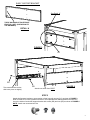
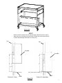
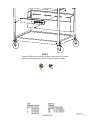
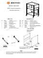
ECILS1 / ECILS1FF
Mobile Computer Workstation
Assembly Instructions
PARTS LIST
Qty
1
1
1
2
4
1
2
2
1
1
Part#
022-2695
010-4513
010-3953
010-4506
022-3085
022-2309
015-0002
015-0003
030-1191
ECF6
Description
Top Shelf w/ grommet hole
Slide Out Shelf
Bottom Shelf
Shelf Support Brackets
Leg Assemblies
Wire Tray
4” Casters w/o Lock
4” Casters w/ Lock
14” Full Extension Slide
Electrical Unit - ECILS1FF ONLY
HARDWARE LIST
Ref
AA
BB
CC
DD
EE
FF
GG
HH
Qty
16
16
12
8
4
2
2
4
1
Part#
030-0300-21S
030-0002
030-0304
030-1228
030-1203
020016
020017
02236
010-1106
Description
5/8” Square Head Bolts
5/16-18 Hex Serrated Nuts
1/4-20 x 5/8” Combo Screws
8-32 x 1/4” Combo Truss Hd Screws
#8-32 Acorn Nuts
#6-32 Hex Nuts - ECILS1FF ONLY
#6-32 x 1/4” Screws - ECILS1FF ONLY
8-32 Hex Flange Nuts
Hex Wrench
TOOLS REQUIRED
Hex Wrench (Provided)
Phillips Screwdriver
Rubber Mallet
TOP
OM
BOTT
FIGURE 1
Align shelf embossed mounting
hole with leg mounting bracket.
2 corners each shelf.
FIGURE 2
STEP 1
Lay 2 legs on a carpeted surface as shown in Figure 1. Slide the top shelf (with hole at rear) and
bottom shelf (with 4 square holes toward front) onto the legs so that the brackets are inside the
shelves (see Figure 2).
1
Align shelf embossed mounting
hole with leg mounting bracket.
2 corners each shelf.
STEP 2
Slide the front legs (they are stamped “LF” and “RF”) onto the
shelves so that the brackets are inside the shelves.
STEP 3
Secure shelves and legs together with bolts
(AA) and nuts (BB) in each corner as shown.
AA
STEP 4
Insert each caster into the bottom of each leg. If caster does
not insert easily, use a rubber mallet to tap caster in place.
Once casters are SECURELY in place, stand unit upright.
BB
2
SHELF SUPPORT BRACKET
See Detail ‘A’
THESE HOLES MUST FACE FRONT
EDGE OF CART. (SIDE OPPOSITE
THE GROMMET)
DETAIL ‘A’
FIGURE 3
CC
EE
To access the correct holes,
slide inner piece out slightly.
FIGURE 4
DD
Attach rear screw & nut FIRST.
STEP 5
Attach shelf support brackets to upper portion of rear legs with screws (CC) as shown in FIGURE 3.
Refer to Detail ‘A’ for correct position of bracket. Then separate each slide and attach the outer section to the inside of each shelf support bracket with screws (DD) and nuts (EE) as shown in FIGURE 4.
NOTE: Attach rear screw and nut first.
CC
DD
EE
3
HH
FIGURE 5
DD
FIGURE 6
STEP 6
Attach the remaining slide pieces to the pull out shelf with screws (HH) and nuts (JJ) as
shown in FIGURE 5. Then slide shelf into cart as shown in FIGURE 6.
HH
4
REAR VIEW
STEP 7
Slide the cord bin between the rear legs and align slotted holes of the cord bin
sides with the (2) mounting holes of the legs. Position the cord bin per Detail ‘B’
to obtain desired height and install four screws (CC).
Leg
Leg
Cord Bin
Cord Bin
2”
2”
6”
6”
4 5/16”
5/16” (min.) up to 3” (max.)
Position #1 (Fixed)
Shelf
Position #1 (Adjustable)
Detail ‘B’
Shelf
5
STEP 8
Align the CFPS electrical unit with the slots in the inside of the cord bin.
Secure the unit in place with screws (FF) and nuts (GG) as shown.
FF
GG
Part # 031-6487
Rev. 03.03.11 CZ
6