1
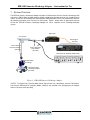
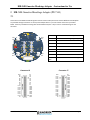
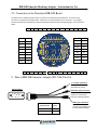
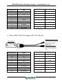
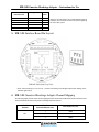
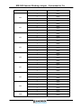
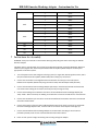
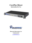
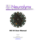
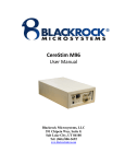
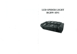
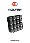
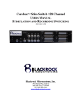
Blackrock
EIB-54K Omnetics Headstage Adapter
PN 7343
Blackrock Microsystems, Inc.
630 Komas Drive, Suite 200
Salt Lake City, UT 84108
Tel: (866) 806-3692
www.blackrockmicro.com
EIB-54K Omnetics Headstage Adapter - Instructions for Use
1 System Overview
The EIB-54K Omnetics Headstage Adapter integrates a Blackrock 64-Channel Omnetics Headstage with
a Neuralynx EIB-54-Kopf electrode interface board, providing 48 electrode channels for recording neural
signals, 4 channels for recording from low-impedance EMG electrodes and 2 sets of differential channels
for providing stimulation (stim+ and stim- for return path). Figure 1 below shows an application overview
of how the EIB-54K Omnetics Headstage Adapter fits into a complete neural recording/stimulation
system.
Digital Hub
Commutator
Neural Signal
Processor
Dale to EIB-54K
Omnetics Adapter
(PN 7344)
Dale to DAC/A-M
1700 Adapter
(PN 7345)
Differential AC Amplifier (Model 1700)
CerePlex M64
Headstage
EIB-54K Omnetics
Headstage Adapter
(PN 7343)
Figure 1: EIB-54K Omnetics Headstage Adapter
**NOTE: The Digital Hub, CerePlex M64, Neural Signal Processor, Commutator, and the A-M Systems
Four-Channel Differential AC Amplifier (Model: 1700) are not included in the packaging for this adapter
and must be purchased separately.
LB-0459 DRAFT Rev 1.00
Page 2
EIB-54K Omnetics Headstage Adapter - Instructions for Use
2 EIB-54K Omnetics Headstage Adapter (PN 7343)
2.1
Connections to the Blackrock Neural Signal Processor and the A-M Systems Four-Channel Differential AC Amplifier
are provided through connectors on the top of the adapter board. A pin-out of these connectors is provided
below. LEDs are provided for tracking with the NeuroMotive System. All pin-outs are viewed looking into the
connector.
Connector
S3+
S3-
S2+
S2-
S1+
S1-
S4+
S4-
Connector Description
J1
Power connector for lighting LEDs (+/- V)
J2
S3+,S3-
J3
S2+, S2-
J4
S4+, S4-
J5
S1+, S1-
J6
Connection to CerePlex M64 Bank B (or C)
J7
Connection to CerePlex M64 Bank A
LED1, LED2,
LED3
LEDs used for NeuroMotive tracking
Connector J6
GND
NC
NC
NC
NC
NC
NC
E3
E1
CH47
CH45
CH43
CH41
CH39
CH37
CH35
CH33
R1
LB-0459 DRAFT Rev 1.00
R2
NC
NC
NC
NC
NC
NC
E4
E2
CH48
CH46
CH44
CH42
CH40
CH38
CH36
CH34
GND
Connector J7
GND
CH31
CH29
CH27
CH25
CH23
CH21
CH19
CH17
CH15
CH13
CH11
CH09
CH07
CH05
CH03
CH01
R1
R2
CH32
CH30
CH28
CH26
CH24
CH22
CH20
CH18
CH16
CH14
CH12
CH10
CH08
CH06
CH04
CH02
GND
Page 3
EIB-54K Omnetics Headstage Adapter - Instructions for Use
2.2 Connection to the Neuralynx EIB-54K Board
The bottom of the adapter provides a direct connection to the Neuralynx EIB-54K board. Pin-outs for each
connector are provided in the figure below. All pin-outs are viewed looking into the connector. For mapping
between the Neuralynx EIB-54K board and the Blackrock EIB-54K Omnetics Headstage Adapter, refer to section 6
below.
S3-
S3+
GND
CH28
CH27
CH26
CH25
CH24
CH23
CH22
CH21
GND
S2-
S2+
CH20
CH12
CH52
CH51
CH19
CH11
CH44
CH36
CH18
CH10
CH43
CH35
CH17
CH09
CH42
CH34
CH16
CH08
CH41
CH33
CH15
CH07
CH40
CH32
CH14
CH06
CH39
CH31
CH13
CH05
CH38
CH30
CH50
CH49
CH37
CH29
S4-
S4+
GND
CH45
CH46
CH47
CH48
R1
R2
CH04
CH03
CH02
CH01
GND
S1-
S1+
3 Dale to EIB-54K Omnetics Adapter (PN 7344) Pin-Out
+/- V Power Connection
Provides power to LEDs for
NeuroMotive tracking
Dale Connector
Stimulation Input Connectors
Connects to differential stimulus
channels on the EIB-54K
Omnetics Headstage Adapter
L H D A
J E B
M K F C
LB-0459 DRAFT Rev 1.00
Stimulation Input
Connector Pins
Wire
Color
StimStim+
Black
Blue
HDMI Type-D Connector
Connects to HDMI
connector on the Blackrock
CerePlex M64 Headstage.
Page 4
EIB-54K Omnetics Headstage Adapter - Instructions for Use
HDMI/D Pin#
Description
GND
9
+DATA
B
+V
11
-DATA
C
-V
D
+CLK
12
+CLK
E
+DATA
14
-CLK
F
-DATA
16
-V
H
-CLK
J
Stim- (black)
19
+V
K
Stim+ (blue)
1
GND
L
Not Connected
Not Connected
2, 3, 4, 5, 6, 7, 8, 10,
13, 15, 17, 18
Not Connected
M
Dale Connector Pin
Signal
A
4 Dale to DAC/A-M 1700 Adapter (PN 7345) Pin-Out
Stimulation Output Connector
Connects to the stimulus
connector of the A-M Systems
Differential AC Amplifier
(Model: 1700)
HDMI Type-A Connector
Connects to the HDMI
connector on the Blackrock
DAC.
Dale Connector
L H D A
J E B
M K F C
Dale Connector Pin
Signal
HDMI/A Pin#
Description
A
GND
7
+DATA
B
+V
9
-DATA
C
-V
D
+CLK
10
+CLK
E
+DATA
12
-CLK
F
-DATA
17
-V
H
-CLK
J
Stim- (black)
18
+V
K
Stim+ (red)
19
GND
L
Not Connected
Not Connected
1,2, 3, 4, 5, 6, 8, 11,
13, 14, 15, 16
Not Connected
M
LB-0459 DRAFT Rev 1.00
Page 5
EIB-54K Omnetics Headstage Adapter - Instructions for Use
Stimulation Output
Connector Pins
Signal
Wire
Color
A
B
Stim+
Stim-
Blue
Black
C
Not Connected
NA
D
Not Connected
NA
E
Not Connected
NA
*Refer to the A-M Systems Four-Channel Differential AC
Amplifier user manual for further instructions regarding
the use of this system.
5 EIB-54K Interface Board Pin Layout
NOTE: Each tetrode (TT1, TT2, TT3, etc…) is laid out according to the diagram above when looking at the
TT# label right side up
6 EIB-54K Omnetics Headstage Adapter Channel Mapping
The following table provides the channel mapping between the Neuralynx EIB-54K electrode interface board
and the Blackrock 64-Channel Omnetics Headstage Electrode Channel.
EIB-54K
TETRODE
TT1
LB-0459 DRAFT Rev 1.00
EIB-54K
TETRODE/EEG CHANNEL
NEURAL SIGNAL PROCESSOR
ELECTRODE CHANNEL
1
CH01
2
CH02
3
CH03
Page 6
EIB-54K Omnetics Headstage Adapter - Instructions for Use
TT2
TT3
TT4
TT5
TT6
TT7
TT8
TT9
TT10
LB-0459 DRAFT Rev 1.00
4
CH04
1
CH38
2
CH39
3
CH40
4
CH41
1
CH33
2
CH32
3
CH31
4
CH30
1
CH51
2
CH36
3
CH35
4
CH34
1
CH42
2
CH43
3
CH44
4
CH52
1
CH24
2
CH23
3
CH22
4
CH21
1
CH28
2
CH27
3
CH26
4
CH25
1
CH11
2
CH10
3
CH09
4
CH08
1
CH16
2
CH17
3
CH18
4
CH19
1
CH50
2
CH13
Page 7
EIB-54K Omnetics Headstage Adapter - Instructions for Use
3
CH14
4
CH15
1
CH07
2
CH06
3
CH05
4
CH49
1
CH48
2
CH47
3
CH46
4
CH45
E1
1
CH29
E2
1
CH37
E3
1
CH12
E4
1
CH20
TT11
TT12
7 Instructions for Assembly
WARNING: Always use antistatic or electrostatic discharge (ESD) safe gloves when connecting the EIB-54K
Omnetics Adapter
CAUTION: Refer to the individual user manuals for the Neuralynx EIB-54K, CerePlex M Headstage, Blackrock
Cerebus System, Digital Hub, and A-M Systems Differential AC Amplifier (Model 1700) for the set-up and
appropriate use of these systems.
1.
Turn off all power to the Neural Signal Processing System (i.e. Digital Hub, Neural Signal Processor) and AM Systems Differential AC Amplifier (Model 1700) before making any connections.
2.
Connect the commutator to the Digital Hub and the Stimulus connector(s) on the A-M Systems
Differential AC Amplifier (Model 1700) using the Dale to DAC/A-M 1700 Adapter Cable (PN 7345).
3.
Connect the EIB-54K Omnetics Headstage Adapter (PN 7343) to the Neuralynx EIB-54K interface board.
Use caution when making this connection and verify that all pins align correctly.
4.
Connect the Headstage to the Omnetics connectors of the EIB-54K Omnetics Headstage Adapter (PN
7343). NOTE: When connected, the labeling on the Omnetics connectors should face the same direction.
5.
Connect the stimulation input connectors to the desired differential stimulation channels on the EIB-54K
electrode interface board.
6.
Connect the power line from the Dale to EIB-54K Adapter Cable to the power connector on the EIB-54K
Omnetics Headstage Adapter board. All three LEDs on the surface of the adapter should light up.
7.
Connect the EIB-54K Omnetics Headstage Adapter to the electrodes according to the instructions
provided by Neuralynx for the use of the EIB-54K electrode interface board.
8.
Power on each system to begin stimulating and recording through the adapter.
LB-0459 DRAFT Rev 1.00
Page 8
EIB-54K Omnetics Headstage Adapter - Instructions for Use
8 Warranty
Blackrock Microsystems, Inc. warrants that its products are free from defects in materials and manufacturing for a
period of one year from the date of shipment. Blackrock will, at its option, repair or replace any product that does
not comply with this warranty. This warranty is voided by:
1.
Any modification or attempted modification to the product done by anyone other than an
authorized Blackrock employee
2. Any abuse, negligent handling or misapplication of the product.
This constitutes the sole warranty made by Blackrock, LLC. There are no other warranties, expressed or implied,
which extend beyond those described herein or to anyone other than the original purchaser, including the implied
warranties of merchantability and fitness for a particular purpose. In no event shall Blackrock Microsystems, LLC.
be liable for any incidental or consequential damages, or for the infringement of any patent rights or third party
rights due to the use of its products.
8.1 Return Merchandise Authorization (RMA)
In the unlikely event that your adaptor needs to be returned to Blackrock for repair or maintenance, do not send
any equipment back without a Return Merchandise Authorization Number. An RMA number will be issued to you
by a Blackrock representative. If you need to obtain an RMA number, you may contact a product support
representative at (801) 582-5533 or toll free at (866) 806-3692.
Once an RMA number has been issued, it is important to safely pack the returned item for shipping back to
Blackrock. It is preferred that you save the original boxes and packing materials that your system arrived in for
return shipment. Please address the package as follows:
Blackrock Microsystems, LLC
ATTN: RMA#
630 Komas Drive, Suite 200
Salt Lake City, UT 84108 USA
Tel: (801) 582-5533
LB-0459 DRAFT Rev 1.00
Page 9