1
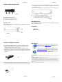
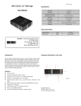
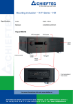
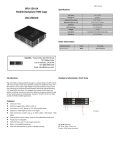
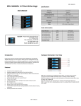
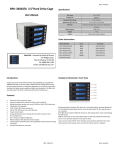
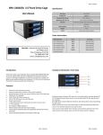
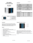
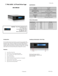
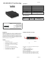
BPU‐2535 SATA 2.5 5” Hard Drive Cage e B BPU‐2535 Specificcation: User’s M Manual Hot Swap 2 x2.5”H HDD Staandard Drive Bays 3.5” Drivve: 1 Dimeension (W x H x D D) 3.98 x 0.98 x 55.75 inches Material Aluminum m Body HDD Interface 2.5 SATA AI/II Weight 0.6lb bs Connector SSATA15‐pin power and 7‐pin Data Indicators Power O On: Green, Green off not working orr no HD. Order I nformation: iStarUSA – Powered by iStarUSA Grou up 27 Phillips Drivve 72 City of Industry, CA 9174 48 Tel: (888) 989‐1189 m Email: [email protected] Intro oduction: The BP PU‐2535 internal d drive cage is a com mpact and cost effe ective solution for an internaal 3.5” drive cage w with two 2.5” drive bays. It providess an extra storage within a compact design n to satisfy many application needs. The BPU‐2535 is constru ucted of aluminum m material that pro ovides best heat d dissipation require ed for high performance 2.5 5” laptop SATA driives. With mirrorin ng technique (RAID D 1), multaneously, whicch the BPU‐2535 is able to maintain data in two disk drives sim backup. provides extra protection on critical data b ures: Featu Aluminum Fraame Hard Drive Interface: SATA I/II Drives Form Factor: 1 x 3.5” Bay for 2 x 2.5” Hard Disk D mance Transfer Ratte up to 3.0 Gb/s High Perform Support RAID D 0 and 1 Functions (need an additio onal RAID controller) er/ Slave Setting Point to Pointt, Free from Maste With one 4Pin Power and two 7 7Pin Signal Connectors DDs or SSD. Energy Savingg on Using 2.5” HD LED Indicatorrs for Power & HDD D access BPU‐2535 Model Nuumber: Color: UPC Code: BPU‐25355 Black 8468813000499 Hardwaare Informatiion: Front Vieew A A3 A1 A1 a A2 Picture A A44 A5 A6 A7 A1: HDD 00 LED‐‐‐Green: HDD D working Green O Off: Not working o or no HDD.. A1a: Poweer LED — Green: PPower on A2: HDD 1 LED — Green Onn: HDD Working Gree n Off: Not workingg or no HDD A3 : Uppe r cover & HDD exttractor A4 : Lowe r cover & HDD exttractor A5 : Uppe r HDD Safety Lockk (Push right to opeen & push left to lo ock) A6 : Push tthe rise high posittion to open the up pper & lower coveer A7 : Lowe r HDD Safety Lockk (Push right to opeen & push left to lo ock) BPU‐2535 BPU‐2535 Hard dware Information: Rear V View B11 B2 B3 BPU‐2535 4) Then, m mount the BPU‐25335 on the 3.5” spaace using the includ ded screws to mou unt it on thee device (desktop,, case… etc.) and m make all the cable connected properly and it iss ready for use. 5) See thee drawing of the tw wo ways to mount BPU‐2535 on the device (See Picture F) Picture B B1 : SA ATA 15pin power connector B2 : SA ATA 7pin data conn nector for HDD 0 B3 : SA ATA 7pin data conn nector for HDD 1 HDD In nstallation: urity Lock Secu Upper HDD Safety Lock & & Lower HDD Safety Lock. (Push righ ht to open & push left to lockk). See Picture C. Open the upper & lower covver and put the HDD inside the cagee. You can install o one wo HDDs. Picture D D HDD or tw Accesso ories: Hard dware Installa ation Procedu ures ATA cables 2 SAT Neceessary screws iStarUSSAcare: Please follow the following procedures to complete the hard dware installation: 1) Opeen the package and d take out the prod duct and make surre the product is bran nd new and all the necessary parts are included. If daamage or shortage occurred, please contact your distriibutor or reseller. 2) Unlo ock the upper and lower covers (see picture C), push the lock rightward and open n the two covers aand then, put the ttwo 2.5"SATA HDD D inside the box (Seee Pictu ure D). Pictture D 3) Afteer both HDDs installed, push both covers back like picture C and then, pu ush the llock button leftwaard to lock both covers to secure the HDD inside propeerly. BPU‐2535 We will hhelp you navigate o our website to find d the information that you need. Go to www w.istarusa.com, and d click on live chat Bar. bubble a bove the Search B ng by to take yourr questions. Visit Our tech nicians are standin http://ista rusa.com/supportt/ , and you will reeceive a technical support ticcket to help track yyour requests from m the beginning to o the end. O Or you can contact us @ 888‐989‐1189. diation Norm FCC and CE Rad FCC mply with limits for Class B digital device pursuant to Part 15 of Federal Communications Commission This equipment haas been tested and found to com (FCC) rules. CE This equipment haas been tested and found to com mply with the limits of the Europea an Council Directive on the appro oximation of the law of the member states relating to eelectromagnetic compatibility (89/ 9/336/EEC) according to EN 5502 22 Class B. FCC and CE Com mpliance Statement These limits are deesigned to provide reasonable p rotection against frequency interfference in residential installation.. This equipment generates uses and can radiate radio ffrequency energy, and if not instaalled or used in accordance with the instructions may cause harm mful interference to radio communication. H However, there is no guarantee thhat interference will not occur in te elevision reception, which can be e determined by turning the equip pment off and on. The usser is encouraged to try and correect the interference by one or mo ore of the following measures: Re eorient or relocate the receiving antenna, Increasee the separation between the equuipment and the receiver, connecct the equipment into an outlet on n a circuit different from that to wh hich the receiver is connnected to. CAUTION! munications Commission warns tthe user that changes or modifica ations to the unit not expressly approved by the party responsible e for The Federal Comm the compliance coould void the user’s authority to ooperate the equipment. BPU‐2535