1
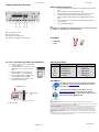
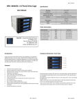
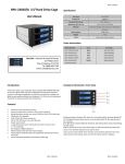
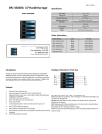
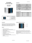
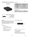
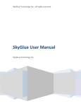
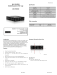
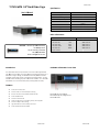
T‐7M1‐SA ATA 3.5””Hard Drivve Cage T-7M1-SATA Specificcation: User’s M Manual Hot Swap 1x3.5””HDD Cooling Fan 1x800mm Sttandard Drive Bayys 5.25” D Drive: 1 Dim mension (W x H x D) 5.75 x 1.65 x 7.32 inches Material Aluminum Design with Conductive Dissipation HDD Interface SATA I/II/III, SAS I/II Groo oves Weight 2 lb bs Cable SATA Cable Inccluded (1pcs) Order I nformation: iStarUSA – Powered P by iSta arUSA Group 727 Phillips P Drive City of Industrry, CA 91748 Tel: (88 88) 989‐1189 Email: [email protected] Intro oduction: Model N Number: Color: UPC Code: T‐7M1‐SSATA‐BLACK Black 8446813010740 T‐7M1‐SSATA‐RED Red 8446813010788 T‐7M1‐SSATA‐BLUE Blue 8446813010757 T‐7M1‐SSATA‐SILVER Silver 8446813010795 T‐7M1‐SSATA‐BPL Plastic 8446813010733 (lockablee handle) Hardwaare Informatiion: Front Vieew The T‐77M1‐SATA mobile rack by iStarUSA is an aluminum ho ot‐swappable HDD cage. W With unique comp pact size and high performance p SAS/SATA interface, the T‐ 7M1‐SATA is tough in strrength, but flexible e in functionality. Additional A blower coolingg fan provides extrra cooling in unfavvorable operating conditions. c The LED indicattor enables monito oring of power and d hard drive activitties. The T‐7M1‐SA ATA audio m mobile rack is constructed with quality and designed for f versatility. Featu ures: Power/Drive Activity LEDs Point to Pointt, Free from Maste er/Slave Setting Best Air Ventilation with 1x80m mm HDD Blower Faan Power ON/OFFF Button D‐1: Poweer LED, green wheen lid. D‐2: HDD D activity LED, orannge when lid. D‐3: Poweer Switch Aluminum Metal Handle Cable‐less Co onnection, Supportt Plug & Play, Hot‐Swappable Aluminum Bo ody for Best Coolin ng High Perform mance Transfer Rate e up to 6.0 Gb/s Support SAS I/II I & SATA I/II/III HDD H T-7M1-SATA T--7M1-SATA Hard dware Information: Rear V View T-7M1-SATA T T-7M1-SATA Quick I nstallation Procedure: 1.. 2.. 3.. 4.. 5.. Open up the hhandle bar from th he tray; take out th he HD trays from the t HD cage. Secure all screews to the HD attaached with HD trayy. Place the hardd drive tray(s) with h HD installed, bacck into the cage un nit. Connect data and power cable onto the rear end of cage unit. (Make sure thhat the date cabless connected to thee motherboard side as well). ntil Operating Syste em Turn on the Poower of your computer and wait un finish loading up. D‐3 Power Button. Turn on the D 6.. Note: For steps 66‐ if the operatingg system installed with a HD inside of HD cage, please make sure you ddo turn on the Pow wer from the cagee switches D‐3. D‐4: 15‐pin power connector D‐5: 7‐pin data connector HD LED switch. (default: left) D‐6: H D‐7: H HD LED‐pin. (for exxternal activity LED D use) Accesso ories: 2.5” or 3.5” Hard Drive Disk to o the trays Insstallation: 11. 22. 33. 44. 55. Insert 2.5” orr 3.5” Hard Drive in nto the HDD Tray from the e cage. Use the proviided screws and faasten HD into highlighted 2.5” or 3.5” holes to the cage trays. Make sure Se ecure with screw holes h from the Bottom of o 2.5” or 3.5” Hard d Drive’s. After the scre ew installation, slid de the HDD Tray back to the t HDD Canister Base. B Next, follow the t Quick Installation in next page for the rest r of the Setup. ATA cables 1 SAT Screews Option al Accessoriees: HD Traays Blacck Model N Number UPC Code: BPU‐HSTTRAY‐BLACK 8468813000635 Redd BPU‐HSTTRAY‐RED 8468813000659 Bluee BPU‐HSTTRAY‐BLUE 8468813000642 Silveer BPU‐HSTTRAY‐SILVER 8468813000673 Plasttic BPU‐HSTTRAY 8468813000628 iStarUSSAcare: 3.5” HD D Screw Holes 2.5” HD Screw w Holes We will h help you navigate our website to fin nd the information that you need d. Go to www.istaarusa.com, and clicck on live chat bubble above th he Search Bar ur questions. Visit Our tech nicians are standiing by to take you http://istaarusa.com/supporrt/ , and you will rreceive a technical support ticcket to help track your requests fro om the beginning to the end. Or yo ou can contact us @ @ 888‐989‐1189 diation Norm FCC and CE Rad FCC has been tested and found to ccomply with limits for Class B d digital device pursuant to Part 15 of Federal Communications s This equipment h Commission (FC CC) rules. CE This equipment h has been tested and found to ccomply with the limits of the Eu uropean Council Directive on tthe approximation of the law off the member states relating to o electromagnetic compatibilityy (89/336/EEC) according to EN N 55022 Class B. FCC and CE Com mpliance Statement These limits are d designed to provide reasonablle protection against frequency y interference in residential ins stallation. This equipment gene erates uses and can radiate rradio frequency energy, and if n not installed or used in accord dance with the instructions may cause harmful interference to o radio communication. However, there is no guarante ee that interference will not occ cur in television reception, whic ch can be determined by turnin ng the equipment off an nd on. The user is encouraged to try and correct the interfere ence by one or more of the follo owing measures: Reorient or relocate r the receiving antenn na, Increase the separation betw ween the equipment and the re eceiver, connect the equipmentt into an outlet on a circuit different from that to which thee receiver is connected to. CAUTION! The Federal Com mmunications Commission warrns the user that changes or m modifications to the unit not exp pressly approved by the party responsible HD Tray: Bottom B View 3.5” HD Screw Holes for the compliancce could void the user’s autho ority to operate the equipment. T-7M M1-SATA T-7M1-SATA A