1
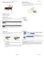
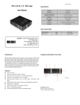
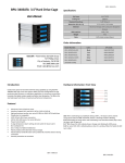
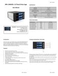
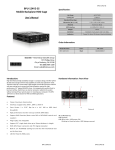
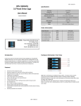
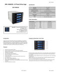
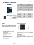
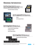
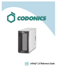
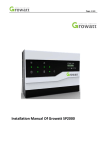
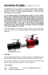
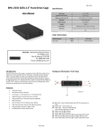
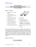
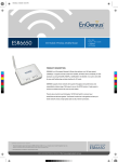
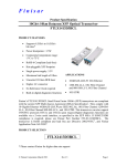
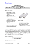
BPU‐12 26‐SA Mobiile Backpla ane HDD C Cage BPU U-126-SA Specificcation: Manual User’s M Hot Swap 6x2.5”HDD Cooling Fan 2x440mm Standard Drive B ays 5.25” Drive: 1 D Dimension (W x H x D) 5.75 x 1.665 x7 inches Material Alumin num Body HDD Interfacee 2.5 SA ATAI/II/III Weight 1.6 lbs Connector Standard 4Pin M Molex &7 pin Data a Indicators LED fo or Power Order I nformation: Model Number: Color: UPC Code: BPU‐1226‐SA Black 8446813000048 iStarUSA – – Powered by iSStarUSA Group p 727 Phillips Drive e ustry, CA 91748 8 City of Indu Tel: (888) 989‐1189 9 @istarusa.com m Email: sales@ Intro oduction: High leevel RAID and high h availability storagge in a compact de esign, the BPU‐126 6‐SA adds extra storage and h hot‐swap capability to satisfy any ap pplication needs. TThe minum material witth BPU‐1226‐SA is constructed of light weight and durable alum two co ooling fans to ensu ure best heat dissip pation required fo or high performancce 2.5” laptop SATA hard drives. It is designed with excellent frront to back vent w. Hard drives can also be removed o or added to the syystem without turn ning airflow off you ur system power o or restarting your ccomputer. The BPU U‐126‐SA is an ide eal solutio on for RAID and JBOD applications. ures: Featu A Aluminum Frame In nterface: Support SATA‐I, SATA‐II, SA ATA‐III FForm Factor: 1 x 5.25” Bay for 6 x 2.5 5” SATA Hard Disk Driver SSupport 2.5” HDD height up to 9.5 m mm in height. H High performance transfer rate up to SATA 1.5Gb/ss、SATA 3Gb/s、SSATA 66Gb/s SSupport RAID Funcctions (*Note : Nee ed an extra SATA R RAID Control Card) P Plug & play, hot sw wappable W With 4Pin Power and 7 Pin data signaal connectors B Built‐in 2 X 4cm(40 020) cooling fan TTwin color LED indiication for power o on & HDD accessin ng Hardwaare Informatiion: Front Vieew 2 6 1 3 7 A1: to A6:: HDD Tray A7: Blue color: Power onn. HDD being accesssed. Purple: H 5 Picturre A 4 Hard dware Information: Rear V View HDD In nstallation: BPU-126--SA BPU-126-SA Inner tra y with heat disssipation holes. 3 provided screws to o There are four screw holes aat the bottom of eeach tray, use the p 1 mount thee HDD onto the traay. (See Picture D)) 4 Accesso ories: 7 5 9 8 2 6 10 Pictu ure B B1: 4p pin power conne ector B2 & B B3: 40mm Cooli ng Fan B4 to B9: 7pin SATA data port HDD Led Switch B10: H LED Sw witch Indication n description: a) Wh hen it is set to “X” Position, th he front LED do es NOT blink w hile HDD i s being accesse d. pin up when th he system powe er is In thi s case, the harrd drives will sp turned d on. b) Wh hen it is set to “O” “ position, it will blink in blu ue while the HD D is being accessed. D will not spin up until the SA ATA initial signaal is In thi s case, the HDD receivved. (c) Th e default settingg for D10 (HDD LED Switch) is t o “O” position (HDD LED Enable). Secu urity Lock The mechanical lock dessign keeps the HD DDs staying inside the unit and prevvents being taken out while they are running. HDDs b Pictture C1 A A. Picture C2 OPEN the HD DD Tray: Press and pussh on the ‘arrow’ p position rightward d to open each HDD tray (see picture C1.) B B. LOCK the HDD D Tray: After HDD in nstalled onto the HDD tray, slide it into the frame and Pictture D ATA cables 6 SAT Neceessary screws iStarUSSAcare: We will hhelp you navigate o our website to find d the information that you needd. Go to www.istarrusa.com, and clickk on live chat bubb ble above th e Search Bar. ng by to take yourr questions. Visit Our tech nicians are standin http://ista rusa.com/supportt/ , and you will reeceive a technical ssupport ticket to heelp track your requests from the beginning to the end d. Or you can coontact us @ 888‐989‐1189. diation Norm FCC and CE Rad FCC mply with limits for Class B digital device pursuant to Part 15 of Federal Communications Commission (FCC) This equipment haas been tested and found to com rules. CE mply with the limits of the Europea an Council Directive on the appro oximation of the law of the member states This equipment haas been tested and found to com relating to electrom magnetic compatibility (89/336/E EC) according to EN 55022 Classs B. FCC and CE Com mpliance Statement These limits are deesigned to provide reasonable p rotection against frequency interfference in residential installation.. This equipment generates uses and can radiate radio frequuency energy, and if not installed or used in accordance with the instructions may cause harmful in nterference to radio communication. However, there is no guaranntee that interference will not occ ur in television reception, which ccan be determined by turning the e equipment off and on. The user is encouraged to try and correct the interference by oone or more of the following mea asures: Reorient or relocate the rreceiving antenna, Increase the separation s between the equippment and the receiver, connect tthe equipment into an outlet on a circuit different from that to whicch the receiver is connected to. CAUTION! munications Commission warns tthe user that changes or modifica ations to the unit not expressly approved by the party responsible e for the The Federal Comm compliance could void the user’s authority to operaate the equipment. press the fron nt handle forward to lock the HDD ttray on the frame (See picture C2.) BPU-126-SA B BPU-126-SA