1
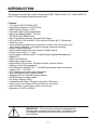
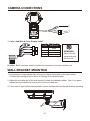
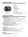
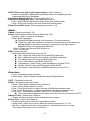
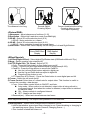
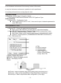
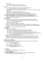
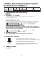
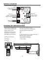
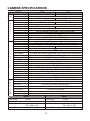
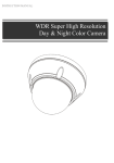
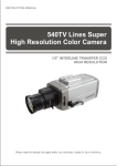
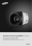
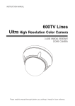
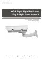
WDR Super High Resolution Day & Night Color Camera 1/3'' DOUBLE SCAN CCD HIGH RESOLUTION WARNINGS: TO REDUCE THE RISK OF FIRE OR ELECTRIC SHOCK, DO NOT EXPOSE THIS PRODUCT TO RAIN OR MOISTURE. DO NOT INSERT ANY METALLIC OBJECTS THROUGH THE VENTILATION GRILLS OR OTHER OPENINGS ON THE EQUIPMENT. CAUTION: CAUTION CAUTION: TO REDUCE THE RISK OF ELECTRIC SHOCK, DO NOT REMOVE COVER(OR BACK). NO USER-SERVICEABLE PARTS INSIDE. REFER SERVICING TO QUALIFIED SERVICE PERSONNEL. EXPLANATION OF GRAPHICAL SYMBOLS The lightning flash with arrowhead symbol, within an equilateral triangle, is intended to alert the user to the presence of uninsulated "dangerous voltage" within the product's enclosure that may be of sufficient magnitude to constitute a risk of electric shock to persons. The exclamation point within an equilateral triangle is intended to alert the user to the presence of important operating and maintenance (servicing) instructions in the literature accompanying the product. PRECAUTIONS Safety ----------------------------------------- Installation ----------------------------------- Should any liquid or solid object fall into the cabinet, unplug the unit and have it checked by the qualified personnel before operating it any further. Do not install the unit in an extremely hot or humid place or in a place subject to excessive dust, mechanical vibration. Unplug the unit from the wall oulet if it is not going to be used for several days or more. To disconnect the cord, pull it out by the plug. Never pull the cord itself. The unit is not designed to be waterproof. Exposure to rain or water may damage the unit. Allow adequate air circulation to prevent internal heat build-up. Do not place the unit on surfaces (rugs, blankets, etc.) or near materials(curtains, draperies) that may block the ventilation holes. Height and vertical linearity controls located at the rear panel are for special adjustments by qualified personnel only. Cleaning -------------------------------------Clean the unit with a slightly damp soft cloth. Use a mild household detergent. Never use strong solvents such as thinner or benzine as they might damage the finish of the unit. Retain the original carton and packing materials for safe transport of this unit in the future. - ii - FCC COMPLIANCE STATEMENT FCC INFORMATION : THIS EQUIPMENT HAS BEEN TESTED AND FOUND TO COMPLY WITH THE LIMITS FOR A CLASS A DIGITAL DEVICE, PURSUANT TO PART 15 OF THE FCC RULES. THESE LIMITS ARE DESIGNED TO PROVIDE REASONABLE PROTECTION AGAINST HARMFUL INTERFERENCE WHEN THE EQUIPMENT IS OPERATED IN A COMMERCIAL ENVIRONMENT. THIS EQUIPMENT GENERATES, USES, AND CAN RADIATE RADIO FREQUENCY ENERGY AND IF NOT INSTALLED AND USED IN ACCORDANCE WITH THE INSTRUCTION MANUAL, MAY CAUSE HARMFUL INTERFERENCE TO RADIO COMMUNICATIONS. OPERATION OF THIS EQUIPMENT IN A RESIDENTIAL AREA IS LIKELY TO CAUSE HARMFUL INTERFERENCE IN WHICH CASE THE USER WILL BE REQUIRED TO CORRECT THE INTERFERENCE AT HIS OWN EXPENSE. CAUTION : CHANGES OR MODIFICATIONS NOT EXPRESSLY APPROVED BY THE PARTY RESPONSIBLE FOR COMPLIANCE COULD VOID THE USER'S AUTHORITY TO OPERATE THE EQUIPMENT. THIS CLASS A DIGITAL APPARATUS COMPLIES WITH CANADIAN ICES-003. NORME NMB-003 DU CANADA. CE COMPLIANCE STATEMENT WARNING THIS IS A CLASS A PRODUCT. IN A DOMESTIC ENVIRONMENT THIS PRODUCT MAY CAUSE RADIO INTERFERENCE IN WHICH CASE THE USER MAY BE REQUIRED TO TAKE ADEQUATE MEASURES. - iii - IMPORTANT SAFEGUARDS 1. 2. 3. 4. 5. 6. 7. 8. 9. 10. 11. 12. 13. 14. 15. 16. Read these instructions. Keep these instructions. Heed all warnings. Follow all instructions. Do not use this apparatus near water. Clean only with dry cloth. Do not block any ventilation openings. Install in accordance with the manufacturer's instructions. Do not install near any heat sources such as radiators, heat registers, stoves, or other apparatus (including amplifiers) that produce heat. Do not defeat the safety purpose of the polarized or groundingtype plug. A polarized plug has two blades with one wider than the other. A grounding type plug has two blades and a third grounding prong. The wide blade or the third prong are provided for your safety. If the provided plug does not fit into your outlet, consult an electrician for replacement of the obsolete outlet. Protect the power cord from being walked on or pinched particularly at plugs, convenience receptacles, and the point where they exit from the apparatus. Only use attachments/accessories specified by the manufacturer. Use only with the cart, stand, tripod, bracket, or table specified by the manufacturer, or sold with the apparatus. When a cart is used, use caution when moving the cart/apparatus combination to avoid injury from tip-over. Unplug this apparatus during lightning storms or when unused for long periods of time. Refer all servicing to qualified service personnel. Servicing is required when the apparatus has been damaged in any way, such as power-supply cord or plug is damaged, liquid has been moisture, does not operate normally, or has been dropped. CAUTION THESE SERVICING INSTRUCTIONS ARE FOR USE BY QUALIFIED SERVICE PERSONNEL ONLY. TO REDUCE THE RISK OF ELECTRIC SHOCK DO NOT PERFORM ANY SERVICING OTHER THAN THAT CONTAINED IN THE OPERATING INSTRUCTIONS UNLESS YOU QRE QUALIFIED TO DO SO. Use Certified/Listed Class 2 power source only. - iv - CONTENTS OF PACKAGE Installation of the camera must be performed by qualified service personnel in accordance with all local and national electrical and mechanical codes. Carefully remove the color camera and its accessories from the carton and verify that they were not damaged in shipment. The contents of the package includes: 1. CAMERA HOUSING KIT 2. This manual 3. L-wrench (5mm) --------------- 1ea (2.5mm) ------------- 1ea 4. ANCHOR (5mm) --------------- 4ea TABLE OF CONTENTS INTRODUCTION 1 CAMERA CONNECTIONS 2 WALL BRACKET MOUNTING 2 CAMERA OVERVIEW 3 CAMERA ADJUSTMENT 3 CONTROL AND CONNECTIONS/DAY&NIGHT I/O/ ALARM OUT TERMINALS 9 WIRING DIAGRAM 10 HOUSING KIT SPECIFICATIONS 10 CAMERA SPECIFICATIONS 11 -v- INTRODUCTION The camera provided high-quality image using SONY Wide Dynamic 1/3” Super-HADII PS 960H CCD and digital signal processing LSIs. Features: 1/3" Super-HADII PS 960H CCD Super high-resolution of 650TV lines Wide Dynamic Range (~x512) Excessive High-Light Compensation Back Light Masking (MAX. 15 area) 2D-NR, 3D-NR (DNR Demo) Day & Night(Auto, Manual, External, Filter delay) 0.4 lux(Color), 0.04 lux(B/W), 0.001 lux(Low-Shutter) @ F1.4 Sensitivity Sens-Up (~x32) Various Detection Method (zone detection, motion trace, face trace, mine area, absent detection, cross object counting, entrance counting) Scene Change Detection Various Alarm Method (Period, Snooze, Polarity Select) Frame Control (Auto, 1~7 sec) Privacy Mask or Mosaic (MAX. 15 area/4-point polygonal/transparency) Digital PTZ White Pixel Remove Back Light Compensation Digital Effect (H/V reverse, 180 degree rotate, inverse, freeze) System Lock (4-Digit password) Auto Electronic Shutter [1/50 ~ 1/100,000] and manual electronic shutter modes [1/50 ~ 1/10,000] C/CS, back-focus cam for easy adjustment Auto and Manual white balance modes Support Line-Lock external synchronization RS-485 Remote camera control On Screen Display (OSD) Compatible with Video, DC type lenses with OSD select Quick connect for Video or DC lens with 4-pin connector User Certified / Listed Class 2 power source only Operates in 12VDC or 24VAC IMPORTANT : The user of this camera is responsible for checking and complying with local, state, and federal laws and statutes concerning the recording and monitoring of audio signals. -1- CAMERA CONNECTIONS 2 1 1. Color Lead Wire & Color Display Label COLOR COLOR BLACK DESCRIPTION BLACK AC24V RED AC24V BLUE RS485(-) BROWN RS485(+) REMINDER: Never aim the camera directly into the sun. DESCRIPTION DC12V WHITE DC12V ORANGE RS485(-) BROWN RS485(+) 2. Video : BNC connector used to connect the camera to a monitor, switcher, etc. WALL BRACKET MOUNTING 1. Use fasteners of appropriate size and type to attach the bracket to the wall surface. Position the housing so that it allow for viewing of the selected area. 2. Adjust the movable arm of the wall bracket to attain the desired position. One it is in place, tighten the bolt located at the pivot point of the movable arm. 3. If you want to pull out the relevant cable, remove the knockout on the wall bracket mounting. 1 2 3 -2- CAMERA OVERVIEW 3 2 4 6 1 5 7 10 8 1 2 3 4 5 6 9 REAR VIEW 7 8 9 10 Left Button Up Button Enter Button Right Button Down Button Day/Night External I/O Motion ALARM OUT RS - 485 UTP(optional) Power Indicator Video Output Connector (BNC) UTP or BNC Transformation Switch (optional) AC/DC Compatible Input Terminal CAMERA ADJUSTMENT <White Balance> 1) Auto(Auto White Balance) : AWB mode (1800ºK ~10500ºK) 2) Push/Hold : Push&Hold Mode. To find the Optimal setting for the current luminance environment in this mode, set the direction towards a sheet of white paper and select Hold and press enter button. If the environment changes, readjust it. 3) CRS Mode(Color Rolling Suppression) : Decrease color rolling effect. This operation take some time about 10 seconds and user can stop this operation by pressing enter button. When CRS Mode is on, color tone can be weak. 4) Indoor : Set color temperature to indoor (3200ºK) 5) Outdoor : Set color temperature to outdoor (6300ºK) 6) FL(Fluorescent Light) : Set color temperature to fluorescent light fixed gain. 7) User(User Set White Balance) : Adjust red or blue gain. R(R-GAIN):Adjust R-GAIN value (0-255) B(B-GAIN):Adjust B-GAIN value (0-255) <Auto Exposure> 1) SHT(s)(Electronic Shutter) : Select Shutter mode. Auto(1/60(1/50) ~ 1/100,000 Auto run, Manual 8 step from 1/60(1/50) ~1/10,000). 2) FLC(Flicker-less) : Flicker-less On/Off. 3) AGC(Auto Gain Control) : AGC Gain(Off, Low, Middle, High) 4) Sens-Up(Slow Shutter) : Maximum Low-Shutter select. (x2-x32 and Off) 5) Offset Add : Force the picture to turn up at low luminance environment. <BLC/WDR> 1) Normal AE : BLC/WDR function off. 2) WDR(Wide Dynamic Range) : Wide dynamic range mode on. -3- 3) EHLC(Excessive High Light Compensation) : EHLC mode on. excessive lighting compensation is performed when the weighting on the high-brightness side is increased. 4) Auto(Auto Weighting BLC) : Auto weighting BLC on. 5) Spot(User Setting BLC area) : Spot metering mode on. Posi : OSD mode to adjust the position of the spot metering area. Size : OSD mode to adjust the size of the spot metering area. 6) Zone(Preset BLC area) : Fixed metering area mode. (1-9). <Mask> 1) Mask: Select mask area(1-15). 2) Func: Select mask function.(Privacy, BLM, Both, Off). Privacy : Area to screen on the display. BLM : Back Light Mask. Selected BL Mask area that will be except of the auto exposure If there is a high light installed in a limited environment such as an apartment parking garage or gas station entrance, removing the high light makes it possible to view car license plates efficiently. Both : Privacy function and BLM function on. Off : Function off. 3) Edit : Mask area edit. Edit mode take effect during Func not Off. Size : adjust the size of the Privacy and BLM mask area. Posi : adjust the position of the Privacy and BLM mask area. Tilt : adjust tilting of Privacy and BLM mask area. Color: Select Privacy and BLM mask (0-14). Transparency: Select Privacy mask transparency (Default 3/0-3). Mosaic: Select Privacy and BLM mask mosaic On/Off Adj. Mosaic: Adjust Privacy and BLM mask mosaic level (0-31). <Detection> Func : Detection function selection. Sens Down : Adjust to Motion Sensitivity using left/right Buttons. 1) OFF : Detection function off. 2) Zone : Area motion detection mode. Zone : Select Motion detection zone (Zone1-4). Func : Select Motion detection on/off. Size : Press Enter button to adjust the size of the Motion detection area. Posi : Press Enter button to adjust the position of the Motion detection area. Link Zoom : Select Motion detection with D-PTZ function that On/Off . When the motion triggered in the area, zoom and move to the area with D-PTZ. 3) Motion Trace : Motion trace mode on. Tracks an object through a scene and generates an alarm. 4) Face Trace : Face Trace mode on. Tracks face through a scene and generates an alarm. Sens Down : lower value is more widen the scope to judge face. (0~127) Min Size : Minimum face size configuration (0 : minimum face size is to none) The result of face trace can be inaccuracy. -4- 5) Mine : Mine area mode. By this function, User can draw motion detection area with free dotting Set Mine : Press the Enter button to Set Mine mode. < > : Move : Mine Zone move using the Left and Right buttons. UP:Set : Mine Zone setting using the Up button. DN:Clr : Mine Zone clear using the Down buttons. ENT:End : Press the Enter button to set Mine mode end. Clr All : Press the Enter button to set Mine area clear. Display : Select Mine Display On/Off. 6) Absent : Press the Enter button to Absent detection mode. Absent : Detect object appeared or removed the scene. Sens Down : Adjust sensitivity of Absent check(0-255). In low luminance environment, the accuracy is down of the result. Because object color is effect to auto exposure, the accuracy is down of the result If the object is too big, the accuracy is down of the result. 7) Cross : Cross counting mode. Zone : Select Cross Zone using the Left and Right buttons (Zone 1, Zone 2). Size : Adjust the size of the Cross zone. Posi : Adjust the position of the Cross zone. Direction : Select Cross Direction. Alarm Cnt : Set alarm out cross count. Alarm count number is delaying number before output alarm. Reset Cnt : Cross count reset. If object is passing so fast through the two area, counting is not operating. In this case, adjust to expand space between two area or adjust to decrease size of area. If passing object is too long, counting result can be inaccuracy. In this case, adjust to expand space between two area or adjust to decrease size of area. If two object passing the area in the same time, the result can be inaccuracy. 8) Entrance : Entrance counting mode. The object move in through the entrance, counting number increases. Size : Press Enter button adjust the size of the Entrance zone. Posi : Press Enter button adjust the Position of the Entrance zone. Alarm Cnt : Set alarm out entrance count. Alarm count number is delaying number before output alarm. Reset Cnt : Entrance count reset. Crossing object is not considered. / Several object will not be detected. If the distance is increases between the camera and entrance, the result can be inaccuracy. -5- The distance is too long Several Object Crossing Object <Picture/DNR> Camera Installed at the ceiling Crossing object is none One object is passing. 1) Sharpness : Adjust sharpness of outlines (0~15) 2) Resolution : Select high resolution mode (Low/Mid/High) 3) 2D-NR : Select 2D noise reduction level (0~6) 2D-NR : Noise reduction on a frame 4) 3D-NR : Select 3D noise reduction level (0~31) 3D-NR : Noise reduction through the several frame 5) DNR Demo : Select DNR Demo Display On/Off using the Left and Right Buttons None DNR Effect Display DNR Applied Display <Effect/Special> 1) d-Effect(Digital Effect) : Select digital Flip/Rotate state (Off/Rotation/Mirror/V Flip ) 2) Nega : Select negative color state(on/off) 3) d-PTZ (Digital Pan, Tilt, Zoom) : Adjust d-PTZ. Func : Press the Enter button to turn digital zoom on/off. Zoom : Use the Left and Right buttons adjust to digital zoom(0-255). Pan&Tilt : Press the Enter button to access the Pan&Tilt. Use the Left and Right buttons adjust to digital pan Use the Up and Down buttons adjust to digital tilt Press the Enter button to exit. PT Reset(Pan & Tilt Reset) : Press the Enter button to reset digital pan and tilt. 4) Freeze : Select the still mode on/off 5) Frame Control: Select term of refresh rate for output video. This function is useful to reduce the recording data storage. Func : Select frame control mode to ON/OFF, and Auto. Auto mode : When motion is not detected, output video is being refresh in configured interval. And when the motion is detected, output video is switched to real time video. ON : Always refresh in configured interval. OFF : Always real time video. Renewal(sec) : Select an interval between two frame. When object start moving, The output video possible to cut a little time. 6) ScnChg/Unfoc : Select scene change/unfocus detection On/Off . Inform that whether scene have been changed or not. Detect breaking or changing in the watching scene (Spray, Screen Camera, Changing Scene…) This function is linked with alarm out -6- In low luminance environment, the accuracy is down of the result. In very low luminance environment, operation is not be performed. It is not be performed when moving object is exist. <System Setup> 1) Cam Info : Camera basic information display Cam ID/Baud rate/Protocol/Firmware Ver./CCD Type/Lens Type 2) General Setup System Lock : Configuration Lock. When system lock is set to “Lock”, User must to input 4-character password to enter OSD menu. Default password is “0000”. Change PID : Change the administrator's password Move cursor with OSD Key and Press Enter to input the character. Comm(RS 485 Communication) : Press the Enter button to access the Comm. Cam ID : Select the camera ID (001 - 255). Baud Rate : Select serial communication speed (2400/4800/9600/19200). Protocol : RS-485 protocol. (COMMAND/FASTRAX/PELCO-D/Pelco-D) Title : Edit camera title. A. Title B. Delete character C. Character table D. Command line - Clear : Clear Title - Cancel: Cancel editing - Accept: Save Title Display : Display item select. Cam ID : Camera ID display On/Off. Title : Title display On/Off. Alarm . Period : Alarm out period (5sec/10sec/20sec/30sec/1min/5min/Cont.) Snooze : Alarm out snooze(Off/5sec/10sec/20sec/30sec/1min/5min) Active pol : Alarm output active state configuration. (Low, High) -7- System Init Cancel : Back to General Setup Menu. Confirm : Initialize all data. (Factory Default) 3) Lens Iris : DC, Video, Manual Lens selected Iris : adjust AE Speed DC lens and video lens can adjust AE Speed Normal AE Ref (Auto Exposure Reference Level) : Press the Enter button to access the AE Ref. Ref Lvl : Adjust AE base reference level. WDR Ref : Press the Enter button to access the WDR Ref. Ref Lvl : Adjust the WDR long-time control Base Reference Level. 4) LLC(Line Lock Control) : Press the Enter button to access the Line Lock mode. Func : Select Line Lock function On/Off using the Left and Right buttons. Phase : Adjust Line Lock sync phase using the Left and Right buttons. (0~100) Activate only AC power inputted. 5) White Pixel Det Exe : Press Enter button to turn White Pixel Compensation mode Start. ENT to Adj : Press Enter button to start White Pixel Compensation start. Proc : Process to find white pixel. Done : Process ended Det Count : Result of white pixel detection. Func : Select erasing white pixel function On/Off using the Left and Right buttons. Det Level : Select the judgment level of white pixel using the Left and Right buttons (1~16) Det View : Select display of detected white pixel. 6) Day/Night Mode : Select D&N mode. Auto : Filter operates automatically according to brightness. Day : The camera outputs the video image only in color. Night : The camera outputs the video image only in black and white. Ext : This menu automatically converts the COLOR Mode into the B/W Mode or vice versa depending on illumination with an external sensor. Night Mode : Select B/W Burst On/Off Delay(s) : Adjust the working time of the filter when D&N mode is Auto (1-60 sec). D>N Level : Select switching level Day to Night when D&N mode is Auto (0-15). N>D Level : Select switching level Night to Color when D&N mode is Auto (0-15). <Bottom Line Menus> When user entered in main menu and sub-menus, following menus will be appeared. I.Main Manu (menu in bottom lines) A. Exit : Save & Exit. B. Load : Load Default Value. II.Sub Menu (menu in bottom lines) A. Return : Return to previous menu. B. Exit : Save & Exit 1) Exit Menu Save&Exit : Current environment values save. Exit : Disappear menu osd. 2) Load Default Setup Yes : Load default to current configuration. and return to previous menu. No : No operation, and return to previous menu. -8- CONTROL AND CONNECTIONS/DAY&NIGHT I/O / ALARM OUT TERMINALS 1 UTP(optional) 2 UTP(optional) 3 4 D&N I/O IN OUT 5 COM GND 6 ALARM OUT 7 8 RS-485 RS 485+(RX) RS 485-(TX) 1) UTP Connections/Video output (optional) 1 PIN: UTP2 PIN: UTP+ 2) DAY&NIGHT I/O Terminals To select Day/Night mode using external equipment, connect control lines to the appropriate terminals. DAY&NIGHT OUTPUT (4pin) It is the function that can turn on external IR LED Lamp by detecting the sensitivity on the AGC level when the D&N mode is set "AUTO" on the OSD menu of the camera. 4 DAY&NIGHT OUTPUT 5V/10mA : IR LED ON(NIGHT) 5 COM 0V : IR LED OFF(DAY) DAY&NIGHT EXTERNAL INPUT (3pin) It is the function that can be switched to DAY Mode or NIGHT Mode by receiving the D&N on/off signal from external light sensor or IR LED LAMP. When D&N Mode is set "External" on the OSD menu of the camera. 5 3 Open contact : DAY Close contact : NIGHT COM DAY&NIGHT INPUT 3) ALARM OUT (6pin) Motion detection signals are output through this port. (On High (5V)) 4) POWER INPUT TERMINAL This terminal accepts a DC12V or AC24V power source from a DC12V or AC24V ac +/-10% 60/50Hz +/- 1Hz. CLASS 2 + DC 12V ~ AC 24V ~ Use Certified/Listed Class 2 power supply only. It is recommended to use the DC power supply that can support inrush current over 0.75A 5) CAMERA CONTROL 7 PIN: RS 485+ 8 PIN: RS 485- -9- WIRING DIAGRAM * HEATER AND BLOWER J3 (B+) 24Vdc Out to Blower (Ground) J6 J4 24Vac Out to Heater J5 Ground 24Vac Power Supply Input J1 Ground 24Vac Power Supply Output 24 Vac HOUSING KIT SPECIFICATIONS Camera Housing Window Size Camera Housing Construction 2.5" W x 2.3" H (6.4cm x 5.9cm) Die-cast, extruded, and sheet aluminum Camera Housing Finish Light-gray ployester powder coat Wall Bracket Pan Adjustment 360 Wall Bracket Tilt Adjustment 70 Wall Bracket Locking Method 4 holes for fasteners of a suitable size & type. Mount to a secure solid surface. Total Dimension(WxHxL) 5.5" W x 9.68" H x 20.5" D (14cm x 24.6cm x 52.02cm) 9.15Ib( 4.15kg) Total Weight Unit: inch(cm) 5.5(14) 2.5(6.4) 9.68(24.6) 2.3(5.9) 20.5(52.02) - 10 - CAMERA SPECIFICATIONS NTSC MODEL Power source POWER Power consumption Power input Image sensor Effective pixels G Scanning system E Scanning frequency N Sync. system E Resolution R Min. illumination A Video output L S/N Ratio Camera Control White Balance Exposure BLC/WDR AGC Control Shutter Speed Sens-Up Day/Night F Video Analytics U D-Zoom N DNR C Privacy Zone T Camera Title I Display Cam ID O Effect N Bad Pixel System Lock Frame Control Language Other Function C O N N E C T O R & ETC. Video output Auto iris output DC 12V / AC 24V ± 10% 4.5 Watts 2-Pin Terminal block Power Cord 1/3" Super-HADII PS 960H CCD 976x494 976x582 2:1 interlace 15.734KHz(H) x 59.94Hz(V) 15.625KHz(H) x 50Hz(V) Internal / Line lock 650TVL 0.4 Lux (COLOUR), 0.04 Lux (B/W), 0.001 Lux (Low-shutter) 1.0 Vp-p (75 ohm, composite) 50dB (AGC OFF) RS485 (Faxtrax, Pelco D, Pelco P) Auto / CRS / Push&Hold / Indoor / Outdoor / FL / User Auto / Manual Shutter / Flickerless/ Low Light Control / Offset Add EHLC / AUTO / SPOT / ZONE/ BLM WDR: x512 (Level Adjust) Low / Middle / High / Off 1/60-1/10,000 (Auto:1/100,000) 1/50-1/10,000 (Auto:1/100,000) x32 Auto / Day / Night / Ext Zone / Motion trace/ Face trace/ Minefield/ Absent / Cross / Entrance/ Scene Change Detection ~ x256(Zoom) / D-PTZ Support 2DNR, 3D NR :Gain Adjust, DNR Demo Max 15 (Tilt, Color, Transparency, Mosaic) Alpha Numeric On / Off (Cam ID, Title) 001~255 V-Flip / Mirror / Rotation / Nega&Posi / Freeze / Sharpness Adj/Done (Max 64 point), Detected pixel display Lock/Unlock (need Password input when Locked) Auto, Off ~ 7Sec( Use for saving storage) English Admin Password, Alarm Setting(Period, Snooze, Polarity) BNC , UTP(option) 4-Pin mini din jack (standard connection) Lens mount C/CS mount (Selected through back focus) Lens 5-50mm F1.4 DC iris or 2.8-12mm F1.4 DC iris Mounting hole 1/4''-20 UNC (top or bottom) Operating temperature Operating humidity -10 C ~ +50 C 0 ~ 96% (non-condencing) Heater Blower Power Supply Power Consumption Blower ON Blower OFF PAL 100-240V~50Hz ± 1Hz 24 Vac 3.4W t C > 35 C +/-3 C T F > 95 F +/-5 F t C < 20 C +/-3 C Power Supply Power Consumption Heater ON Heater OFF - 11 - 24 Vac 20W t C < 5 C +/- 3 C T F < 41 F +/- 5 F t C > 15 C +/- 3 C MEMO WDR Super High Resolution Day and Night Color Camera PRINTED IN KOREA 50302784A