1
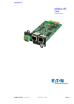
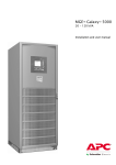
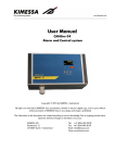
MGE Galaxy 5000
40-130 kVA 480 V
Operation
Table of Contents
About This Manual ......................................................................................................... 1
Symbols Used ................................................................................................................... 1
Companion Manuals ......................................................................................................... 1
Find Updates to this Manual ............................................................................................. 1
Overview .............................................................................................................................. 2
User Interface....................................................................................................................
Display Screens.................................................................................................................
Basic Operation of Display ........................................................................................
Measurements ...........................................................................................................
Alarms .......................................................................................................................
Status ........................................................................................................................
Settings .....................................................................................................................
Controls .....................................................................................................................
2
2
2
3
3
4
4
4
UPS Configuration ......................................................................................................... 6
Access to the Personalization Functions.............................................................. 6
Personalization Settings .................................................................................................... 6
Operation ............................................................................................................................ 8
Operating Modes............................................................................................................... 8
Normal (Double Conversion) Mode ............................................................................ 8
ECO Mode (Single UPS Only) .................................................................................... 8
Load on Battery Power .............................................................................................. 9
Operation of Mimic-Panel LEDs ......................................................................................10
Operation Procedures........................................................................................................11
Shut Down a Single UPS ............................................................................................11
Restart a Single UPS..................................................................................................12
Shut Down a Parallel Configuration ...........................................................................13
Restart a Parallel Configuration .................................................................................14
Isolate UPS ................................................................................................................15
Return to Normal Operation .......................................................................................18
Restart the UPS Unit for which Switch Q3BP (10) is ON and the Other Switches are
OFF ...................................................................................................................................19
Restart the UPS for which All Switches are Set to OFF...................................................20
Operation of the Relay Communication Card (Dry Contacts) ...............22
Standard Mode ..................................................................................................................22
Programmable Mode.........................................................................................................23
List of Operating Status Conditions That Can be Assigned to an SECI Output ..............23
Maintenance ......................................................................................................................26
Life Cycle Monitoring (LCM) ..........................................................................................26
Servicing Batteries ............................................................................................................27
IMPORTANT SAFETY INSTRUCTIONS FOR SERVICING BATTERIES ........................27
Troubleshooting ..............................................................................................................28
Identification of Alarms ....................................................................................................28
Alarm or Status Display Messages List ............................................................................29
990-5219-001
MGE Galaxy 5000 40-130 kVA 480 V
i
ii
MGE Galaxy 5000 40-130 kVA 480 V
990-5219-001
About This Manual
This manual describes the startup, shutdown, and normal operation of the MGE Galaxy 5000 with
information on the user interface display and display menu structure. For maintenance the manual
describes alarm conditions, UPS isolation operation and maintenance and safety information on servicing
batteries for the MGE Galaxy 5000.
Symbols Used
WARNING: Indicates an electrical hazard, which, if not avoided, could result in injury
or death.
Caution: Indicates a hazard, which, if not avoided, could result in injury or death.
Note: Indicates important information.
See: Indicates that more information is available on the subject.
Companion Manuals
For additional information about the MGE Galaxy 5000, see the following documents:
• MGE Galaxy 5000 Installation – 990–5217–001
• MGE Galaxy 5000 Receiving & Unpacking – 990–5218–001
Find Updates to this Manual
You can check for updates to this manual on www.apc.com. Look for the latest letter revision (A,
B etc.) of the manual.
990-5219-001
MGE Galaxy 5000 40-130 kVA 480 V
1
Overview
User Interface
The UPS is operated using the control and display interface.
A.
Graphical Display
B. Load protected LED
C. Minor fault LED
D.
Major fault LED
E. Help key
F. Function keys. Each
key corresponds to
a function presented
on the display. The
function of each key
changes depending on
the menu displayed on
the screen.
G.
Menu key. This button
provides direct access
to the main menu.
H.
ON button.
I.
OFF button.
J.
PFC ON LED
K.
UPS ON LED
L. Operation on battery
power LED
M.
Load supplied LED
N.
Bypass in operation
LED
Display Screens
Basic Operation of Display
2
MGE Galaxy 5000 40-130 kVA 480 V
990-5219-001
A
Press the Menu key to access the Main Menu.
B
Press the Help key for information on the pictogram functions. The key must be held down.
Measurements
The Measurements display screens consist of the following measurements screens:
1. Press the Menu key to return to the Main Menu.
2. Use the function keys ↑ or ↓ to highlight Measurements on the display.
3. Press the function key ← to select Measurements.
4. Use the function keys ↑ or ↓ to select between the following measurements:
• Battery Measurements
• Voltage Measurements
• Current Measurements
• Power Measurements
• Frequency Measurements
• Ratios Measurements
• Parallel Measurements (option)
5. Press the function key ← to select the required measurements screen.
Alarms
Detailed information on all alarms is supplied on the display. See the“Troubleshooting“ section for
a list of possible alarm messages in the display.
1. Press the Menu key to return to the Main Menu.
2. Use the function keys ↑ or ↓ to highlight Alarms on the display.
3. Press the function key ← to select Alarms.
4. Use the function keys ↑ or ↓ to select between the alarm messages.
5. Press the function key ← to select the required alarm screen.
990-5219-001
MGE Galaxy 5000 40-130 kVA 480 V
3
Status
The Status display screens consist of the following Status screens:
1.
2.
3.
4.
Press the Menu key to return to the Main Menu.
Use the function keys ↑ or ↓ to highlight Status on the display.
Press the function key ← to select Status.
Use the function keys ↑ or ↓ to select between the following two Status screens:
• Time stamped events
• Statistics
5. Press the function key ← to select the required Status screen.
Settings
The Settings display screens consist of the following Settings screens:
1.
2.
3.
4.
Press the Menu key to return to the Main Menu.
Use the function keys ↑ or ↓ to highlight Settings on the display.
Press the function key ← to select Settings.
Use the function keys ↑ or ↓ to select between the Settings screens:
• Language
• Date / time
• Display contrast
• Buzzer volume
• Personalization
• Output voltage
• Password
• Dry-contact settings
5. Press the function key ← to select the required Settings screen.
Controls
The Controls display screens consist of the following Controls screens:
1.
2.
3.
4.
Press the Menu key to return to the Main Menu.
Use the function keys ↑ or ↓ to highlight Controls on the display.
Press the function key ← to select Controls.
Use the function keys ↑ or ↓ to select between the Controls screens:
• Reset Alarms
• Inverter on
• Inverter off
• Force load transfer to inverter
• Force load transfer to bypass
• Desynchronize inverter from bypass
• Resynchronize inverter and bypass
4
MGE Galaxy 5000 40-130 kVA 480 V
990-5219-001
• Tests LEDs
• Buzzer OFF
• Enable LCM indications
• Disable LCM indications
5. Press the function key ← to select the required Controls screen.
990-5219-001
MGE Galaxy 5000 40-130 kVA 480 V
5
UPS Configuration
Access to the Personalization Functions
Caution: Personalization must be carried out with switches Q1 (8) and Q5N (11) open
(OFF) and switch Q4S (9) closed (ON).
1. Press the menu key (A).
2. Select Settings, then Personalization using the
function keys (B) ↑ or ↓.
3. Confirm by pressing the function key (B) ←).
4. Enter the password by successively selecting
each icon using the corresponding function key.
5. Confirm by pressing the function key (B) ←.
6. To save the personalization settings, confirm by
pressing the function key (B) ←.
The password is factory set to:
For information on how to change the password,
see “Settings“.
Personalization Settings
Operating Mode
Function
Factory setting
Options
UPS operating mode
NORMAL
UPS automatic start
Disabled
Enabled
Authorized number of starts
4
1 to 255
Delay before reset of number of
executed automatic starts
4 seconds
1 to 60 seconds
Function
Factory setting
Options
UPS output frequency
60 Hz
60 Hz
Tolerance for bypass AC source
8%
0.5 – 1 – 2 – 4 %
Synchronization speed with bypass
AC source
2 Hz / s
1 Hz / s
Frequency
6
MGE Galaxy 5000 40-130 kVA 480 V
990-5219-001
Automatic Bypass
Function
Factory setting
Options
Transfer to bypass AC source
Enabled
Disabled – disabled when limiting
Transfer to bypass with bypass AC
source out of tolerances
Enabled
Disabled
Function
Factory setting
Options
Low battery warning threshold if
battery monitor inactive
40% remaining backup time
20 – 60 – 80 % remaining backup
time
Low battery warning threshold if
battery monitor active
4 minutes of battery backup time
1 to X minutes of battery backup
time
Interval between two battery tests
30 days
1 to 180 days
Battery
990-5219-001
MGE Galaxy 5000 40-130 kVA 480 V
7
Operation
Caution: All operations concerning system start-up and compliance with standards and
regulations, including those related to the battery cabinet, must be carried out by trained and
certified personnel before using the UPS.
Operating Modes
Normal (Double Conversion) Mode
This is the standard operating mode, set by default in the factory. Two possible cases:
1. Normal AC source available: LED (A) is ON.
The load is protected by the UPS.
2. Normal AC source not available: LED (B) is ON.
The buzzer sounds intermittently. Operation on battery
power LED on the mimic-panel is green.
The load is supplied by the UPS from battery power.
Note: The display indicates any anomalies related to the AC source or the UPS as well
as remedial action if applicable. Press the function key indicated by the display to turn
the buzzer OFF.
ECO Mode (Single UPS Only)
The main advantage of this mode is that it reduces the consumption of electrical power. ECO mode may be
selected exclusively via the control panel on the UPS. Three possible scenarios:
1. Bypass AC source available: LED (A) is ON.
The load is supplied in ECO mode.
2. Bypass AC source not available: LED (A) is ON. The
buzzer sounds intermittently. The load is automatically
supplied in normal mode via the Normal AC input.
8
MGE Galaxy 5000 40-130 kVA 480 V
990-5219-001
3. Both normal and Bypass AC sources not available or
out of tolerance: LED (B) is ON. The buzzer sounds
intermittently. The load is supplied by the UPS from
battery power.
Note: The display indicates the UPS operating status conditions and the required actions.
Load on Battery Power
The load continues to be protected by the UPS when the normal AC source is not available. Power is
supplied by the battery.
Transfer to Battery Power
LED (B) is ON.
The buzzer sounds intermittently.
The load is supplied by the battery.
End of Battery Power
LED (C) is ON.
The buzzer sounds intermittently.
The load is transferred on the bypass AC input if
it is present.
990-5219-001
MGE Galaxy 5000 40-130 kVA 480 V
9
Operation of Mimic-Panel LEDs
The MGE Galaxy 5000 system is simple to operate and yet provides a wealth of continuous monitoring
and diagnostic features to ensure proper operation. Operators gain access to information in the MGE
Galaxy 5000 system through the display and its integrated LED mimic panel.
The mimic diagram displays information directly on the front panel. Segments are green when the function
is active. Segments are OFF when the function is not active. Segments are red when a fault has occurred
in the function.
A.
PFC ON LED
B. UPS ON LED
C. Operation on battery power LED
D.
Load supplied LED
E. Bypass in operation LED
F. ON button
Start Up Single UPS on Normal AC Input
Steps
Action
LED (A)
LED (B)
LED (C)
LED (D)
LED (E)
1
Q1 open
Off
Off
Off
Off
Off
2
Close Q1
green
Off
red
Off
red
3
Close Battery CB
green
Off
Off
Off
red
4
Close Q4S
green
Off
Off
Off
green
5
Close Q5N
green
Off
Off
green
green
6
Open Q3BP
green
Off
Off
green
green
7
Press ON button
(F)
green
green
Off
green
Off
Start Up Single UPS on Bypass AC Input
Steps
Action
LED (A)
LED (B)
LED (C)
LED (D)
LED (E)
1
Q4S open
Off
Off
Off
Off
Off
2
Close Q4S
Off
Off
red
Off
green
3
Close Q5N
Off
Off
red
green
green
4
Open Q3BP
Off
Off
red
green
green
5
Close Q1
green
Off
red
green
green
6
Close Battery CB
green
Off
Off
green
green
7
Press ON button
(F)
green
green
Off
green
Off
10
MGE Galaxy 5000 40-130 kVA 480 V
990-5219-001
Operation Procedures
Shut Down a Single UPS
The UPS remains energized unless it is shut down.
1. Press a button to exit sleep mode.
2. Press the OFF button (A) for 3 seconds.
The load is no longer protected by the UPS.
It is supplied via the bypass.
3. Set the battery circuit breaker of the auxiliary
cabinets to OFF.
4. Set the input switch Q1 (B) to OFF.
The charger no longer operates to keep the
batteries fully charged.
5. Open the upstream circuit breakers of the
Normal AC source and Bypass AC source to
completely power off the UPS.
990-5219-001
MGE Galaxy 5000 40-130 kVA 480 V
11
Restart a Single UPS
Check that switches Q4S (B) and Q5N (C) are closed. If this is the case, continue with this procedure,
otherwise refer to “Return to the Normal Operation, Single UPS“.
1. Set the Normal AC source input switch Q1 (A)
to the ON position.
2. Wait until the end of the start sequence.
3. Set the battery circuit breaker of the auxiliary
cabinets to the ON position.
The UPS starts automatically.
LED (D) is ON. The load is protected by the
UPS.
If the LED (D) remains OFF, press the ON
button (G) (the UPS is in manual start mode) and
confirm if necessary by pressing the function
key (H) marked ←.
If the LED (C) still remains OFF and either of
the LEDs (E) or (F) is ON, a fault has occurred
(see “Identification of Alarms“.
12
MGE Galaxy 5000 40-130 kVA 480 V
990-5219-001
Shut Down a Parallel Configuration
1. Press a button on each unit to exit sleep mode.
2. Press the OFF button (A) on each unit for 3
seconds.
The load is no longer protected by the UPSs.
It is supplied via the bypass.
3. Set the battery circuit breakers of the auxiliary
cabinets to the OFF position.
4. Set the input switch Q1 (B) in each UPS to the
OFF position.
The charger no longer operates to keep the
batteries fully charged.
5. Open the upstream circuit breakers of Normal
AC source and Bypass AC source to completely
power off the installation.
990-5219-001
MGE Galaxy 5000 40-130 kVA 480 V
13
Restart a Parallel Configuration
Check that switches Q4S (B) and Q5N (C) are closed. If this is the case, continue with this procedure,
otherwise refer to “Return to Normal Operation, Parallel UPS“.
1. Check that the output switch CB2 in the external
system bypass cabinet is closed.
2. Check that the bypass switch CB1 in the external
system bypass cabinet is open.
Then carry out steps 3 to 5 below on each of the
UPSs.
3. Set the Normal AC source input switch Q1 (A)
to the ON position.
4. Wait until the end of the start sequence.
5. Set the battery circuit breaker of the auxiliary
cabinets to the ON position.
The UPSs start automatically. On each unit,
LEDs (E) and (F) go OFF and LED (D) goes
ON.
The load is protected by the UPSs.
If the LED (D) remains OFF, press the ON
button (G) on each UPS (the UPS is in manual
start mode) and confirm if necessary by pressing
the function key (H) marked ←.
If the LED (D) still remains OFF and either of
the LEDs (E) or (F) is ON, a fault has occurred
(see “Identification of Alarms“).
14
MGE Galaxy 5000 40-130 kVA 480 V
990-5219-001
Isolate UPS
Isolate Single UPS
To isolate the UPS from the electrical power source and supply the load directly by the normal or bypass
AC source, follow the instructions below:
1. Press a button to exit sleep mode.
2. Shut down the UPS by pressing the OFF button
(A) for 3 seconds.
The load is no longer protected by the UPS.
3. Set bypass switch Q3BP (D) to ON.
4. Set output switch Q5N (E) to OFF.
5. Set the battery circuit breaker of the auxiliary
cabinets to OFF.
6. Set the input switch Q1 (B) to OFF.
7. Set the switch Q4S (C) to OFF.
8. Wait until the display and LEDs go off.
The load is no longer protected by the UPS, but
continues to be supplied with AC power. UPS
maintenance or servicing can now be carried
out.
WARNING: Power is present on
the power connection terminals.
990-5219-001
MGE Galaxy 5000 40-130 kVA 480 V
15
Isolate Parallel UPS Without External Bypass Cabinet
Shut down and isolate the first UPS:
1. Check that the two UPSs are operating.
2. Press a button to exit sleep mode.
3. Shut down the UPS by pressing the OFF button
(A) for 3 seconds.
4. Set output switch Q5N (E) to OFF.
5. Set the battery circuit breakers of the auxiliary
cabinets to OFF.
6. Set the input switch Q1 (B) to OFF.
7. Set the switch Q4S (C) to OFF.
8. Wait until the display and LEDs go off.
The load is still protected by the other UPS.
Maintenance or servicing can now be carried
out on the UPS that has been shut down.
WARNING: Power is present on
the power connection terminals.
Shut down and isolate the second UPS:
9. Press a button to exit sleep mode.
10.Shut down the UPS by pressing the OFF button
(A) for 3 seconds.
11.Set bypass switch Q3BP (D) to ON.
12.Set output switch Q5N (E) to OFF.
13.Set the battery circuit breaker of the auxiliary
cabinets to OFF.
14.Set the input switch Q1 (B) to OFF.
15.Set the switch Q4S (C) to OFF.
16.Wait until the display and LEDs go off.
The load is no longer protected by the UPS, but
continues to be supplied with AC power. UPS
maintenance or servicing can now be carried
out.
WARNING: Power is present on
the power connection terminals.
16
MGE Galaxy 5000 40-130 kVA 480 V
990-5219-001
Isolate Parallel UPS With External Bypass Cabinet
Shut down and isolate one UPS:
1. Check that the total capacity of the remaining
UPSs is sufficient to supply the connected load.
2. Press a button to exit sleep mode.
3. Shut down the UPS by pressing the OFF button
(A) for 3 seconds.
4. Set output switch Q5N (E) to OFF.
5. Set the battery circuit breaker of the auxiliary
cabinets to OFF.
6. Set the input switch Q1 (B) to OFF.
7. Set the switch Q4S (C) to OFF.
8. Wait until the display and LEDs go off.
Shut down and isolate all the UPSs:
9. On each UPS, press a button to exit sleep mode.
10.Shutdown each UPS by pressing their OFF
buttons (A) for 3 seconds.
11.Depress the “transfer initiate” switch on the
SBC. Unlock “KS” and remove key “A”.
12.Insert key “A” into CB1. Unlock and close
CB1.
13.Open CB2 and lock open, and remove key “B”.
14.Insert key “B” into key interlock “KS” and turn
to lock.
15.Open output isolation CB11–16, as applicable,
and open all Q5N (E) switches of each UPS.
16.Open battery CB of each UPS.
17.Open Q1 (B) and Q4S (C) switches of each
UPS.
18.Turn off all inputs to the UPSs.
19.Wait until the control electronics of all UPS
units have fully shutdown.
The load is no longer protected by the UPSs, but
continues to be supplied with AC power. UPS
maintenance or servicing can now be carried
out.
990-5219-001
MGE Galaxy 5000 40-130 kVA 480 V
17
Return to Normal Operation
Return to Normal Operation, Single UPS
1. Check that bypass switch Q3BP (C) is ON and
that all other switches are OFF.
2. Set switch Q4S (B) to ON.
3. Set output switch Q5N (D) to ON.
4. Wait until the display goes on and check that
there are no faults on the static switch on the
bypass line.
5. Set bypass switch Q3BP (C) to OFF.
6. Set the input switch Q1 (A) to ON.
7. Set the battery circuit breaker of auxiliary
cabinets to ON.
The UPS starts automatically.
LED (E) is ON.
If the LED (E) remains OFF, press the ON
button (H) (the UPS is in manual start mode) and
confirm if necessary by pressing the function
key marked ←.
If the LED (E) still remains OFF and either of
the LEDs (F) or (G) is ON, a fault has occurred
(see “Identification of Alarms“).
18
MGE Galaxy 5000 40-130 kVA 480 V
990-5219-001
Return to Normal Operation, Parallel UPS Without External Bypass Cabinet
Restart the UPS Unit for which Switch Q3BP (10) is ON and the Other Switches are OFF
Caution: It is imperative to restart this UPS. Otherwise, load power is lost if the other
UPS is shut down.
1. Set the input switch Q4S (B) to ON.
2. Set output switch Q5N (D) to ON.
3. Check that the UPS is listed by the display, then
confirm by pressing the function keys.
4. Set bypass switch Q3BP (C) to OFF.
5. Set the input switch Q1 (A) to ON.
6. Set the battery circuit breaker of the auxiliary
cabinets to ON.
The UPS starts automatically. LED (E) is
ON. The load is protected by the UPS.
If the LED (E) remains OFF, press the ON
button (H) on each UPS (the UPS is in manual
start mode) and confirm, if necessary, by
pressing the function key marked ←.
If the LED (E) still remains OFF and either of
the LEDs (F) or (G) is ON, a fault has occurred
(see “Identification of Alarms“).
990-5219-001
MGE Galaxy 5000 40-130 kVA 480 V
19
Restart the UPS for which All Switches are Set to OFF
1. Set the input switch Q4S (B) to ON.
2. Set output switch Q5N (D) to ON.
3. Check that all the UPS units present in the
installation are included in the list on the display
and confirm by pressing the function keys.
4. Set the input switch Q1 (A) to ON.
5. Set the battery circuit breaker of the auxiliary
cabinets to ON.
The UPS restarts and LED (E) is ON.
If the LED (E) remains OFF, press the ON
button (H) on each UPS (the UPS is in manual
start mode) and confirm, if necessary, by
pressing the function key marked ←.
If the LED (E) still remains OFF and either of
the LEDs (F) or (G) is ON, a fault has occurred
(see “Identification of Alarms“).
20
MGE Galaxy 5000 40-130 kVA 480 V
990-5219-001
Return to Normal Operation, Parallel UPS With External Bypass Cabinet
1. Check that all switches on the UPSs are set to
OFF.
2. Apply bypass and input power to UPSs.
3. Set switch Q4S (B) on each UPS to ON.
4. Set output switch Q5N (D) on each UPS and
CB11–16, as applicable, to ON.
5. Check that all the UPSs present in the
installation are included in the list on the display
and confirm by pressing the function key on
each UPS.
6. Set CB2 in the external system bypass cabinet
to ON.
7. Set CB1 in the external system bypass cabinet
to OFF.
8. Set the input switch Q1 (A) on each UPS unit
to ON.
9. Set the battery circuit breakers of the auxiliary
cabinets to ON.
The UPS units start automatically. LED (E)
is ON. The load is protected by the UPS.
If the LED (E) remains OFF, press the ON
button (H) on each UPS unit (the UPS is in
manual start mode) and confirm, if necessary, by
pressing the function key marked ←.
If the LED (E) still remains OFF and either of
the LEDs (F) or (G) is ON, a fault has occurred
(see “Identification of Alarms“).
990-5219-001
MGE Galaxy 5000 40-130 kVA 480 V
21
Operation of the Relay Communication
Card (Dry Contacts)
All systems are equipped with this remote transmissions card (also known as SECI). A complete
specification exists for the card used in MGE Galaxy 5000. This card is used for the transmission of
information between the system and the environment. Two inputs and six outputs are available for the user
(see the table below for the default programming).
Standard Mode
It is compatible with all MGE systems that are I2C compatible.
All SA1 microswitches must be set to OFF (if two SECI cards are installed in the unit, the second card
must be identified differently. On the second card, microswitch 1 on SA1 must be set to ON).
In this mode, the relays switch when the UPS changes status. The information listed below is transmitted
if the parameters were enabled.
Inputs
Factory configuration
Other possible signals for each contact
1.A
UPS ON
• Temperature fault in room
1.B
UPS OFF
• Transfer to bypass AC input disabled
• Transfer to bypass AC input disabled if it is out of tolerances
• UPS not synchronized with the bypass AC input
Outputs
Factory configuration
Other possible signals for each contact
1.1
General alarm
• Overload
1.2
Battery fault
• PFC fault
1.3
Load on UPS
• Inverter fault
1.4
Load on automatic bypass
• Charger fault
1.5
Load on battery power
• Automatic-bypass fault
1.6
Low battery warning
• Bypass AC source out of tolerances
• Battery-temperature fault
• Ventilation fault
• Emergency power OFF activated
• Battery circuit breaker(s) open
• Phase inversion on normal or bypass AC input
• Fuses blown
• Transfer to AC bypass disabled
• Operation in ECO mode
• Load on maintenance bypass
The indications 1.X become 2.X for a second identical card in the UPS.
Contacts are of the NO (normally open) type.
(1) The general alarm can be tested by opening the battery circuit breaker.
22
MGE Galaxy 5000 40-130 kVA 480 V
990-5219-001
Programmable Mode
This operating mode is specific to the MGE Galaxy 5000.
Microswitch 3 on SA1 must be set to ON (if two SECI cards are installed in the unit, the second card must
be identified differently. On the second card, microswitch 1 on SA1 must be set to ON).
In this mode, it is possible to assign predefined operating status conditions (see the complete list) to the
various SECI output relays and predefined UPS commands to the SELV inputs.
Assignments are made using the MGE Galaxy 5000 user interface.
List of Operating Status Conditions That Can be
Assigned to an SECI Output
Operating status
conditions
Description
GENERAL ALARM
PFC fault OR
Inverter fault OR
Bypass static switch fault OR
Charger fault OR
Thermal overload on AC bypass OR
ALIN board input fuse blown OR
Q3BP and Q5N are closed simultaneously OR
External Q3BP and external Q5N are closed simultaneously OR
EPO activated OR
Battery backup time ended, shift to wait mode OR
Battery temperature fault > 45ºC, charger shutdown OR
Battery deep discharge OR
Charger shutdown due to battery room temperature outside tolerances OR
Abnormal presence of voltage on the output before closing the bypass static switch.
(frequency converter) OR
UPS in downgraded mode
- External CAN communication fault OR
- Internal CAN communication fault (GDEN, MIZNUS and CHAN) OR
- CAN cable physically cut OR
- CAN communication relay fault OR
UPS personalization fault
BATTERY FAULT
The battery will soon reach the end of its theoretical service life OR
Battery must be checked (following a faulty battery test)
LOAD ON UPS
Inverter connected to the load and operating on normal AC input. Battery operations
due to a BPI or battery test are signalled as operation on the normal AC input.
LOAD ON
AUTOMATIC BYPASS
The static switch on the AC bypass is closed.
LOAD ON BATTERY
POWER
Inverter connected to the load and operating on battery power. Battery operations due
to a battery test are not signalled.
LOW BATTERY
WARNING
Battery has reached the low-battery warning level (voltage or time). The two thresholds
may be user set.
OVERLOAD
One of the unit modules (rectifier, inverter or AC bypass) is overloaded (thermal or
instantaneous).
990-5219-001
MGE Galaxy 5000 40-130 kVA 480 V
23
Operating status
conditions
Description
PFC FAULT
Neutral leg fault OR
Neutral leg IGBT temperature outside tolerances OR
- Voltage difference between 2 DC half-buses outside tolerances OR
- Top DC half-bus voltage outside tolerances OR
- Bottom DC half-bus voltage outside tolerances
PFC fault OR
- DC-bus voltage at end of CSR1 walk-in is lower than a threshold OR
- DC-bus voltage at end of DC walk-in is lower than a threshold OR
- DC-bus voltage is higher than the high threshold OR
— DC-bus voltage is lower than the minimum threshold OR
— Mean DC-bus voltage is higher than the maximum setpoint OR
- Mean DC-bus voltage is lower than the minimum setpoint OR
- DC-bus voltage is higher than the fast hardware threshold OR
- Temperature of the static switch on the AC normal outside tolerances OR
- Temperature of the battery static switch outside tolerances OR
- Rectifier is current limiting OR
- Rectifier thermal overload OR
PFC IGBT base-plate temperature outside tolerances OR
IGBT inductor temperature outside tolerances.
INVERTER FAULT
Inverter short-circuit detected OR
Inverter current limiting OR
Inverter static switch failure OR
Temperature fault on inverter static switch OR
Inverter base-plate temperature outside tolerances OR
Inverter thermal overload OR
Inverter phase-1 fuse has blown OR
Inverter phase-2 fuse has blown OR
Inverter phase-3 fuse has blown OR
Inverter phase-1 voltage amplitude outside tolerances OR
Inverter phase-2 voltage amplitude outside tolerances OR
Inverter phase-3 voltage amplitude outside tolerances OR
Instantaneous inverter voltage outside tolerances OR
Inverter relay for parallel connection is faulty.
CHARGER FAULT
Fault of non-isolated supply on charger board OR
Fault of isolated supply on charger board OR
Opening fault on battery circuit breaker no. 1 OR
Opening fault on battery circuit breaker no. 2 OR
Charger IGBT temperature outside tolerances OR
Difference in charge-current measurements between safety and measurement systems
OR
Charge current on measurement system close to zero OR
Charge current on safety system close to zero OR
Charge current is higher than safety level OR
Difference in voltage measurements between safety and measurement systems OR
Voltage on measurement system close to zero OR
Voltage on safety system close to zero OR
Battery voltage higher than safety level OR
Charger fuse blown.
AUTOMATIC-BYPASS
FAULT
Supply fault for the static switch on the AC bypass OR
Fault on static switch on AC bypass OR
Temperature of the static switch on the AC bypass outside tolerances.
BYPASS AC SOURCE
OUT OF TOLERANCE
Bypass AC source outside of tolerances (voltage and/or frequency).
BATTERY
TEMPERATURE
FAULT
Battery ambient temperature outside tolerances.
VENTILATION FAULT
Excessive temperature on one or more inductors OR
Inverter or AC bypass static switch fan fault.
EMERGENCY POWER
OFF ACTIVATED
EPO set on control-monitoring board OR
EPO set on charger board.
24
MGE Galaxy 5000 40-130 kVA 480 V
990-5219-001
Operating status
conditions
Description
BATTERY CIRCUIT
BREAKER(S) OPEN
One or two Battery circuit breakers is open.
PHASE ROTATION
FAULT
Phase inversion on normal AC input OR
Phase inversion on AC bypass.
FUSES BLOWN
Fuse blown at normal AC input OR
Charger fuse has blown OR
Power supply board fuse has blown OR
Inverter phase-1 fuse has blown OR
Inverter phase-2 fuse has blown OR
Inverter phase-3 fuse has blown.
TRANSFER TO
BYPASS DISABLED
Transfer to AC bypass disabled (control and monitoring board checks for disabling by
the personalization and/or an SECI input).
ECO MODE
ACTIVATED
The unit is operating in ECO mode. It is configured for ECO mode and the static
switch on the AC bypass is closed.
MAINTENANCE
POSITION
Switch Q5N is open.
CHECK THE UPS
A Life Cycle Monitoring alarm has been activated:
• End of warranty
• End of AC capacitor service life
• End of DC capacitor service life
• End of fan service lives
• End of power supply board service life
• End of battery service life
MGE Galaxy 5000 can be equipped with up to two SECI cards maximum. In this case, the second card
must be identified differently. On the second card, microswitch 1 on SA1 must be set to ON.
990-5219-001
MGE Galaxy 5000 40-130 kVA 480 V
25
Maintenance
Life Cycle Monitoring (LCM)
The “Life Cycle Monitoring” (LCM) function provides UPS maintenance advice to guarantee installation
availability for the user.
The display gives three messages enabling the following to be identified:
Status
Display Message
The end of the contractual legal warranty
End of warranty check recommended
Regular maintenance requirements and the end of
service life for consumable components
Technical check recommended
The end of the battery service life
Battery check required
In addition to these messages, the minor fault LED (A) lights up and the buzzer sounds. These messages
can be deleted by pressing the function key (B). This also causes LED (A) to go out, the buzzer to stop and
the removal of the “Global Alarm” remote signalling.
To completely disable LCM indications, use the display to enter the password required to disable the
function.
26
MGE Galaxy 5000 40-130 kVA 480 V
990-5219-001
Servicing Batteries
IMPORTANT SAFETY INSTRUCTIONS FOR SERVICING BATTERIES
Servicing of batteries should be performed or supervised by personnel knowledgeable of batteries and the
required precautions. Keep unauthorized personnel away from the batteries.
When replacing batteries, use the same model and manufacturer of batteries.
Caution: Do not dispose of battery or batteries in a fire. The battery may explode. Do not
open or mutilate the battery or batteries. Released electrolyte is harmful to the skin and eyes.
It may be toxic. A battery can present a risk of electrical shock and high short-circuit current.
The following precautions should be observed when working with batteries:
• Remove watches, rings, or other metal objects.
• Use tools with insulated handles.
• Wear rubber gloves and boots.
• Do not lay tools or metal parts on top of batteries.
• Disconnect charging source prior to connecting or disconnecting battery terminals.
• Determine if the battery is inadvertently grounded. If inadvertently grounded, remove the source of
ground. Contact with any part of a grounded battery can result in electrical shock. The likelihood of
such shock will be reduced if suchs grounds are removed during installation and maintenance.
990-5219-001
MGE Galaxy 5000 40-130 kVA 480 V
27
Troubleshooting
Identification of Alarms
Alarm conditions are identified by LEDs (A), (B), (C) and the buzzer.
LED (A)
LED (B)
-
LED (C)
-
Buzzer
Significance
Intermittent
Normal AC source not available
-
-
Intermittent
UPS shut down following end of battery
power
-
-
Intermittent
UPS shut down on fault requiring servicing
by after-sales support
Detailed information on all alarms is supplied on the display.
• On the screen, select the alarm for which information is required.
• Hold down the corresponding function key to display the possible causes of the fault and the required
action.
28
MGE Galaxy 5000 40-130 kVA 480 V
990-5219-001
Alarm or Status Display Messages List
Display Message
Level
Abnormal bypass operation
Internal and external switches
Abnormal external bypass operation
Internal and external switches
Abnormal presence of output voltage
Fault or state of load
AC Bypass static switch thermal overload
Fault or state on Bypass AC or Bypass Static Switch
Battery circuit breaker 2 open (QF2) (Battery Cabinet
#2 or #4)
Battery circuit breaker open (QF1) (Battery Cabinet
#1 or #3)
Battery deep discharge
Fault or state of standard charger
Fault or state of standard charger
Battery room temperature fault
Fault or state of standard charger
Battery temperature fault
Fault or state of standard charger
Battery test in progress
Fault or state of standard charger
Battery test result not OK
Fault or state of standard charger
Bypass AC backfeed (KA2) fault
Fault or state on Bypass AC or Bypass Static Switch
Bypass AC backfeed (KA2) is open
Fault or state on Bypass AC or Bypass Static Switch
Bypass input phase rotation fault
Fault or state on Bypass AC or Bypass Static Switch
Bypass source outside tolerances
Fault or state on Bypass AC or Bypass Static Switch
Bypass source present
Fault or state on Bypass AC or Bypass Static Switch
Bypass static switch fault
Major Fault on subassembly
Bypass static switch overload
Fault or state on Bypass AC or Bypass Static Switch
CAN communication relay fault
Fault of downgraded mode
CAN communication resynchronization fault
Fault of downgraded mode
Charger fault
Major Fault on subassembly
Charger shutdown by PFC overload
Fault or state of standard charger
Customer communication disabled
Fault, filtering of customer communication
Emergency Power Off (EPO)
Generic fault on equipment
End of theoretical battery service life
Fault or state of standard charger
External sync frequency outside tolerances
Fault or state of external synchronization
External CAN communication fault
Fault of downgraded mode
External Q3BP switch closed (MBC or SBC CB1)
Internal and external switches
990-5219-001
Fault or state of standard charger
MGE Galaxy 5000 40-130 kVA 480 V
29
Display Message
Level
External Q4S switch open (MBC CB3)
Internal and external switches
External Q5N switch open (MBC or SBC CB2)
Internal and external switches
Fan fault
Major Fault on subassembly
Installation overload
Fault or state of installation
Internal CAN communication fault
Fault of downgraded mode
Inverter and bypass desynchronized
Fault or state of inverter
Inverter current limiting
Fault or state of inverter
Inverter fault
Major Fault on subassembly
Inverter fuse blown
Fault or state of inverter
Inverter overload
Fault or state of inverter
Inverter ready for load connection
Fault or state of installation
Inverter starting
Fault or state of installation
Inverter thermal overload
Fault or state of inverter
Load short circuit
Fault or state of load
Loss of communication with UPS 1
Fault of downgraded mode
Loss of communication with UPS 2
Fault of downgraded mode
Loss of communication with UPS 3
Fault of downgraded mode
Loss of communication with UPS 4
Fault of downgraded mode
Loss of communication with UPS X
Fault of downgraded mode
Low battery shutdown
Fault or state of standard charger
Low battery warning
Fault or state of standard charger
Non-redundant installation
Fault or state of installation
Normal AC backfeed (KA1) fault
Fault or state on Normal AC
Normal AC backfeed (KA1) is open
Fault or state on Normal AC
Normal AC fuse blown
Fault or state on Normal AC
Normal AC input phase rotation fault
Fault or state on Normal AC
Normal AC source downgraded
Fault or state on Normal AC
Normal AC source outside tolerances
Fault or state on Normal AC
Normal AC source static switch failure
Fault or state on Normal AC
30
MGE Galaxy 5000 40-130 kVA 480 V
990-5219-001
Display Message
Level
Not enough bypass static switches
Fault or state of installation
Not enough inverters for load connection
Fault or state of installation
Personalization does not match UPS
Generic fault on equipment
PFC fault
Major Fault on subassembly
PFC overload
Fault or state for PFC
PFC thermal overload
Fault or state for PFC
Power supply board fuse blown
Major Fault on subassembly
Q1 switch open
Fault or state on Normal AC
Q4S switch open
Internal and external switches
Q5N switch open
Internal and external switches
Resynchronizing
Fault of downgraded mode
Starting
Fault or state for PFC
Transfer to bypass disabled
Generic fault on equipment
TVSS fault
Major Fault on subassembly
UPSs not connected by CAN cable
Fault of downgraded mode
UPS on external synchronization
Fault or state of external synchronization
UPS personalization fault
Generic fault on equipment
990-5219-001
MGE Galaxy 5000 40-130 kVA 480 V
31
Worldwide Customer Support
Customer support for this or any other product is available at no charge:
• Contact the Customer Support Center by telephone or e-mail. For local, country-specific centers:
go to www.apc.com/support/contact for contact information.
© APC by Schneider Electric. APC and the APC logo are owned by Schneider Electric Industries
S.A.S., American Power Conversion Corporation, or their affiliated companies. All other trademarks
are property of their respective owners.
990-5219-001
April 2011