1
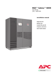
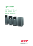
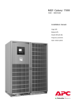
MGE EPS 7000
and MGE EPS 8000
Single and Parallel Operation
Table of Contents
About this Manual .......................................................................................................... 1
Companion Manuals ................................................................................................... 1
Find Updates to this Manual ..................................................................................... 1
Overview .............................................................................................................................. 2
Breakers in the System .............................................................................................. 2
User Interface................................................................................................................ 2
LED Indicators ........................................................................................................... 3
Keys........................................................................................................................... 4
Graphical User Interface ............................................................................................ 5
Symbols ..................................................................................................................... 5
Main Menu Screen ..................................................................................................... 6
Menu Trees .................................................................................................................... 7
Alphanumeric Display Menu Tree .............................................................................. 7
Graphical User Interface Menu Tree........................................................................... 7
Operation Modes ............................................................................................................ 9
Normal Operation......................................................................................................... 9
On-battery Operation ..................................................................................................10
Static Bypass Operation ............................................................................................11
Maintenance Bypass Operation ...............................................................................12
Configuration ....................................................................................................................13
User Interface................................................................................................................13
Set the Display Language and Contrast ....................................................................13
Graphical User Interface ............................................................................................13
Access The Setup Screen .........................................................................................13
Set up Integrated Parallel Network ............................................................................14
Change Password ......................................................................................................14
Change Date and Time ...............................................................................................15
Rename UPS Units and Breakers ..............................................................................16
Hide/Show Elements in a Single System ...................................................................16
Hide/Show Elements in a Parallel System with Centralized Static Switch .................17
Hide/Show Elements in an Integrated Parallel System ..............................................18
Operation Procedures .................................................................................................20
Access System Status Information from the User Interface............................20
Voltage .......................................................................................................................20
990–5204–001
MGE EPS 7000 and MGE EPS 8000
i
Current ......................................................................................................................21
Power Frequency .......................................................................................................21
Battery .......................................................................................................................22
Access System and Status Information from the Graphical User
Interface..........................................................................................................................23
Access Online Trend Information ..............................................................................23
Access Monitoring Information .................................................................................23
Perform a Total Power Off .........................................................................................24
Uninterrupted Transfer Conditions .........................................................................24
Single System Start up from Off/Maintenance Bypass Operation..............................25
Single System Shut Down from Normal to Maintenance Bypass Operation ..............26
Parallel System Start up from Off/Maintenance Bypass Operation ............................26
Parallel System Shut down from Normal to Maintenance Bypass Operation.............27
Perform a Simultaneous Transfer to Static Bypass Operation...................................28
Perform a Simultaneous Transfer to Normal Operation .............................................29
Start up of one UPS Unit in a Parallel System............................................................29
Shut down one UPS Unit in a Parallel System ...........................................................30
Forced Transfers .......................................................................................................30
Maintenance ......................................................................................................................32
Preventive Maintenance .............................................................................................32
Parts Replacement ......................................................................................................32
Troubleshooting ..............................................................................................................33
Audible Alarms .............................................................................................................33
Silence the Alarm.......................................................................................................33
Status and Alarm Messages on the User Interface ............................................33
View List of Current and Stored Alarms.....................................................................33
Reset the Alarm List ..................................................................................................34
List of Alarm Messages .............................................................................................34
Status and Alarm Messages on the Graphical User Interface .........................37
Set the Alarm Delay ...................................................................................................37
View Active Alarms and Events .................................................................................37
View Historical Alarms ...............................................................................................38
Filter Alarms ..............................................................................................................38
Acknowledge All Alarms ............................................................................................38
Clear Alarm Log .........................................................................................................39
ii
MGE EPS 7000 and MGE EPS 8000
990–5204–001
About this Manual
This manual is intended for the users of the MGE EPS 7000 and MGE EPS 8000 systems. It gives an
introduction to the display interface and provides information on configuration, operation, maintenance,
and troubleshooting of the system.
Companion Manuals
For additional information, see the following documents:
• MGE EPS Safety - 990-3514
• MGE EPS 7000 500 kVA 480 V Integrated Parallel Receiving and Unpacking - 990-5227
• MGE EPS 7000 500 kVA 480 V Integrated Parallel Installation - 990-5228
• MGE EPS 8000 555–800 kVA 480 V Integrated Parallel Receiving and Unpacking - 990-5209
• MGE EPS 8000 555–800 kVA 480 V Integrated Parallel Installation - 990-5205
• MGE EPS 8000 1000–1100 kVA 480 V Integrated Parallel Receiving and Unpacking - 990-5208
• MGE EPS 8000 1000–1100 kVA 480 V Integrated Parallel Installation - 990–5207
Find Updates to this Manual
You can check for updates to this manual on www.apc.com. Look for the latest letter revision (A,
B etc.) of the manual.
990–5204–001
MGE EPS 7000 and MGE EPS 8000
1
Overview
Breakers in the System
Breaker
Description
Q1
UPS input breaker: Isolates the UPS from the AC input source and provides input current
protection.
Q5N
UPS/system output breaker (optional): Isolates the UPS/system from the connected load.
Q4S
Static bypass input breaker: Isolates the static switch from the AC bypass input source
and provides back-feed protection.
Q2S
Wrap-around circuit breaker: Supplies the connected load via the AC bypass input source.
SSC cabinet only.
Q3BP
Maintenance bypass circuit breaker (optional): Supplies the connected load via the
maintenance bypass source while the UPS/SSC is being serviced.
QF1
Battery breaker: Disconnects the battery from the UPS and provides isolation and
protection between the UPS and the battery system.
User Interface
A.
Front panel
B. Alphanumeric display
C. Hidden panel
2
MGE EPS 7000 and MGE EPS 8000
990–5204–001
LED Indicators
Front Panel
A.
Load not protected: When the LED is red, the system is in one of the following conditions:
• The load is no longer protected following an inverter shutdown, or the opening of the UPS/system
output breaker (Q5N).
• The battery breaker (QF1) is open, and the battery power is unavailable.
B. Operating problem: When the LED is orange, an operating problem exists. The UPS continues to
protect the connected load.
C. Batteries: When the LED is orange, the batteries support the connected load partly or completely
(battery operation).
D.
Load protected: When the LED is green, the UPS supports the connected load, and the load is
protected by the batteries (normal operation).
Hidden Panel
A.
Emergency shutdown: Red LED indicates that the Emergency Power Off (EPO) or Remote
Emergency Power Off (REPO) has been activated.
B. Rectifier/Charger on: Green LED indicates that the rectifier/battery charger is ON.
C. Rectifier/Charger fault: Indicates an alarm condition within the rectifier/battery charger.
D.
Input outside tolerance: Orange LED indicates that the AC input source is outside voltage or
frequency tolerance.
E. Reserved for future use.
F. Battery temp. outside tolerance: Orange LED indicates that the ambient temperature of the battery is
too high or too low.
G.
Battery charging: Orange LED indicates that the battery is being recharged. This function is only
activated by lead-acid batteries (not sealed lead-acid batteries).
H.
Inverter fault: Red LED indicates an alarm condition in the inverter.
I.
Low batt. shutdown: Orange LED indicates that the battery has reached end-voltage following
a discharge and is shutting down the inverter.
J.
Inverter desynchronized: Orange LED indicates that the inverter is not synchronized with the
bypass source.
K.
Transfer fault: Red LED indicates a transfer fault.
L. Overload: Orange LED indicates an overload alarm condition.
M.
Bypass outside tolerance: Orange LED indicates that the AC bypass input source is outside voltage
or frequency tolerance.
N.
Maintenance position: Orange LED indicates that the breakers QF1, Q4S, Q5N, and Q3BP are set to
maintenance bypass operation. The UPS is not available for load protection.
990–5204–001
MGE EPS 7000 and MGE EPS 8000
3
Keys
Front Panel
A. Inverter on: Starts the inverter.
B. Inverter off: Shuts down the inverter when continuously pressed for three seconds.
Alphanumeric Display
A. LCD display: Displays general status and operating parameters of the UPS.
B. Settings: Provides access to settings.
C. Selection: Used for selection, negative response, or other functions depending on the displayed
message. In parallel systems, this key is primarily used for selecting which UPS or static switch
cabinet the display communicates with.
D. Voltage: Provides access to voltage measurements.
E. Current: Provides access to current measurements.
F. Power/frequency: Provides access to power and frequency measurements.
G. Battery: Provides access to battery measurements.
H. Alarms: Provides access to current or stored alarms.
I. On/Off: Reserved for future use.
J. Confirm/Verify: Used for confirmation, positive response, or other functions depending on the
displayed message.
Hidden Panel
A.
B.
C.
D.
Clear fault log: Clears the alarms stored in the memory.
Alarm reset: Stops the audible alarm.
Battery charge cycle: Starts a battery charge cycle.
Return to float voltage: Forces the rectifier/battery charger back to the float voltage level during a
battery charge cycle.
E. Security: Must be pressed simultaneously with any of the following keys. It helps guard inadvertent
transfer of the load with interruption.
4
MGE EPS 7000 and MGE EPS 8000
990–5204–001
F. Inverter sync/desync: (While holding the Security key down) forces transfer of the inverter output
to desynchronize/synchronize to the AC bypass input source.
G.
Forced transfer (bypass to inverter): (While holding the Security key down) forces transfer of the
load to the inverter output when the bypass is out of tolerance. The inverter must be on. A forced
transfer requires a power interruption to the load of 0.8 seconds.
H.
Forced shutdown (inverter to bypass): (While holding the Security key down) stops the inverter and
transfers the load to the AC bypass source even if the bypass is out of tolerance. A forced transfer
requires a power interruption to the load of 0.8 seconds.
Simultaneous Inverter Transfer Control Panel
Note: This panel is only available in integrated parallel systems.
A.
Transfer enable switch: Must
be pressed simultaneously with
turning the transfer switch to
perform a transfer.
B. Ready to transfer LED: Green
LED indicates that a simultaneous
transfer can be performed.
C. Transfer switch: (While holding
the transfer enable switch down)
initiates transfer to either bypass
or UPS.
Graphical User Interface
The Graphical User Interface functions as the monitoring program for your system. It will not be used for
any control purposes.
Symbols
Circuit – Breaker
Inverter
Bypass Static
Switch
UPS 1
UPS
Rectifier/Charger
990–5204–001
MGE EPS 7000 and MGE EPS 8000
5
Main Menu Screen
Single
A.
UPS name
B. Load Status Lamp
C. Status window
D.
% load
E. Backup Time (in minutes)
F. Power path
G.
Bypass input
H.
Battery Circuit Breaker
I.
Load utility
J.
Batteries
K.
Rectifier/Charger and Inverter
L. Bypass Static Switch
Parallel with Centralized Static Switch
A.
UPS
B. Utility input
C. Bypass input
D.
Load
A.
UPS
Integrated Parallel
B. Utility input
C. Bypass input
D.
Load
E. Load bank
6
MGE EPS 7000 and MGE EPS 8000
990–5204–001
Menu Trees
Alphanumeric Display Menu Tree
General status screen.
This is the default display. It automatically reappears
if the control panel has not been used for ten minutes.
!
V
A
W.Hz
Alarm display
Voltage measurements
Current measurements
Frequency and power measurements
+–
Battery measurements
Reserved for future use (on/off controls)
*
to
confirm
Language and scr een cont r ast set t i ngs
to
set
*
to
confirm
Graphical User Interface Menu Tree
Single
990–5204–001
MGE EPS 7000 and MGE EPS 8000
7
Parallel with Centralized Static Switch
Integrated Parallel
8
MGE EPS 7000 and MGE EPS 8000
990–5204–001
Operation Modes
Normal Operation
Single
Parallel with Centralized Static Switch
During normal operation, the UPS supports the
critical load with conditioned power. The green
line indicates the power flow from the utility/mains
through the UPS system and to the load.
During normal operation, the UPS supports the
critical load with conditioned power. The green
line indicates the power flow from the utility/mains
through the UPS systems and the static switch
cabinet to the load.
Integrated Parallel
During normal operation, the UPS supports the
critical load with conditioned power. The green
line indicates the power flow from the utility/mains
through the UPS systems and the static switch
cabinet to the load.
990–5204–001
MGE EPS 7000 and MGE EPS 8000
9
On-battery Operation
If the AC input supply fails or goes out of tolerance, the UPS transfers to on-battery operation. During
on-battery operation, battery power ensures uninterrupted support to the critical load. When the AC input
supply returns, the UPS automatically returns to normal operation.
If the batteries become depleted before the AC input supply returns, the attached load is transferred to
the AC bypass supply if it is available.
Single
Parallel with Centralized Static Switch
The green line indicates the power flow from the
batteries through the inverter and then to the load.
The green/yellow line indicates the power flow
from the batteries through the inverters and the
static switch cabinet to the load. The yellow color
indicates that the UPS is in battery operation.
Integrated Parallel
The green/yellow line indicates the power flow
from the batteries through the inverters and the
static switch cabinet to the load. The yellow color
indicates that the UPS is in battery operation.
10
MGE EPS 7000 and MGE EPS 8000
990–5204–001
Static Bypass Operation
During bypass operation, the critical load is supplied by the bypass AC input supply via the static switch.
Single
Parallel with Centralized Static Switch
The green line indicates the power flow from the
bypass source through the static switch and to the
load.
The green line indicates the power flow from the
bypass source through the static switch and to the
load.
Integrated Parallel
The green line indicates the power flow from the
bypass source through the static switch and to the
load.
990–5204–001
MGE EPS 7000 and MGE EPS 8000
11
Maintenance Bypass Operation
During maintenance bypass operation, the critical load is supplied directly by the utility/mains power. The
static switch cabinet and the UPS are completely isolated. Batteries are not available as an alternate power
source while the UPS system is in maintenance bypass operation.
Note: In single systems, the Graphical User Interface will be off when the UPS is in
Maintenance Bypass Operation.
Testing UPS 1 in maintenance bypass operation
Testing the bypass switch in maintenance bypass
operation
The green line indicates the power flow from the
utility 2 supply through the Q3BP breaker and to
the load.
The green line indicates the power flow from the
utility 2 supply through the Q3BP breaker and to
the load.
WARNING: Follow the procedure
“Parallel System Shut down from
Normal to Maintenance Bypass
Operation“ before performing
maintenance on the UPS.
WARNING: Follow the procedure
“Parallel System Shut down from
Normal to Maintenance Bypass
Operation“ before performing
maintenance on the static bypass.
12
MGE EPS 7000 and MGE EPS 8000
990–5204–001
Configuration
User Interface
Set the Display Language and Contrast
1. On the alphanumeric display, press the Settings key to access the language selection menu.
2. The display will scroll through the list of languages. Press * to confirm the language selection and
access the contrast menu.
3. Press the arrow to go to the desired contrast level.
4. Press * to confirm the selected contrast and return to the general status screen.
Graphical User Interface
Access The Setup Screen
The default password is “manager”.
1. Press the Setup button.
2. Double-click on the Password field.
3. Type the password navigating through the
keypads.
4. Press the Ok button.
5. Press the Enter button.
990–5204–001
MGE EPS 7000 and MGE EPS 8000
13
Set up Integrated Parallel Network
Note: You must have entered the identification setup screen to continue.
Caution: Each Graphical User Interface must have a unique IP adress, example given
for UPS1.
1. Press the Web setup button.
2. Press the Get IP adress from control panel
button.
3. Verify that the Heartbeat box is blinking.
Change Password
Note: You must have entered the identification setup screen to continue.
The password has a maximum of 20 characters, lower case.
The example below shows the single module screen.
14
MGE EPS 7000 and MGE EPS 8000
990–5204–001
1. Press the Change Password button.
2. Double-click on the New Password field.
3. Type the password navigating through the
keypads.
4. Press the Ok button.
5. Double-click on the Confirm Password field
and type the new password once more following
steps 3 and 4.
6. Press the Enter button.
A.
Once the password is changed, a
Password Changed confirmation
indicator is displayed.
Change Date and Time
Note: You must have entered the identification setup screen to continue.
The example below shows the single module screen.
1. Press the Control Panel button.
990–5204–001
MGE EPS 7000 and MGE EPS 8000
15
2. Double-click on the Date/Time Button.
3. Change the date and time.
Rename UPS Units and Breakers
Note: You must have entered the identification setup screen to continue.
The example below shows the single module screen. For Integrated Parallel, the labels are located on
the UPS ID Setup and System ID setup screens.
Example given for UPS. The principle is the same for all UPS units and breakers.
1. Double-click on the UPS Name field.
2. Type the password navigating through the
keypads.
3. Press the Ok button.
Hide/Show Elements in a Single System
Note: You must have entered the identification setup screen to continue.
The elements that have a green bar will be shown – grey elements will not be shown.
The example below shows the Q4S breaker. The principle is the same for all elements.
16
MGE EPS 7000 and MGE EPS 8000
990–5204–001
1. Press the Q4S button to turn it green (show) or
grey (hide):
A.
Hide/show Q4S and Q1 common feed.
B. Hide/show Q3BP and Q4S common feed.
C. Hide/show battery temperature sensor
(option).
D.
Hide/show battery backup time. The
battery parameters must be set correctly.
E. Hide/show alarm popup screen. If set to
show, a popup screen will appear for every
new unacknowledged alarm. You can also
hide/show the alarm popup screen in the
Alarm/event screen.
F. Hide/show UPS specific alarms.
G.
Hide/show power flow color code.
Hide/Show Elements in a Parallel System with Centralized Static Switch
Note: You must have entered the identification setup screen to continue.
The elements that have a green bar will be shown – grey elements will not be shown.
The example below shows the Q4S breaker. The principle is the same for all elements.
1. Press the System config button.
990–5204–001
MGE EPS 7000 and MGE EPS 8000
17
2. Press the Q4S button to turn it green (show) or
grey (hide):
A.
Select if Load bank circuit breaker is
present.
B. Hide/show battery backup time. The
battery parameters must be set properly.
C. Hide/show number of UPS units in the
system.
D.
Hide/show Q2S connected downstream
of Q4S.
E. Hide/show Static switch, Q2S, Load bank
breaker and UOB breaker status.
F. Hide/show battery temperature sensor
(option) if available.
G.
Set the type of UPS system.
Hide/Show Elements in an Integrated Parallel System
Note: You must have entered the setup screen to continue.
The elements that have a green bar will be shown – grey elements will not be shown.
The example below shows the Q3BP breaker. The principle is the same for all elements.
1. Press the UPS ID Setup button.
A.
Identify the current UPS or remote GUI.
B. Hide/show number of UPS units in the
system.
C. Hide/show system capacity.
D.
Hide/show UPS specific alarms.
2. Press the System ID button.
A.
Hide/show battery temperature sensor
(option) if available.
B. Hide/show battery backup time. The
battery parameters must be set properly.
18
MGE EPS 7000 and MGE EPS 8000
990–5204–001
3. Press the Q3BP button to turn it green (show)
or grey (hide).
990–5204–001
MGE EPS 7000 and MGE EPS 8000
19
Operation Procedures
Access System Status Information from the User
Interface
Voltage
Note: In parallel systems, bypass voltage measurements are shown in the static switch
cabinet.
Press the V key on the alphanumeric display to shift between the different voltage measurements.
1 2 3 4 5 6 7 8
V
A
W.Hz
*
1. Press V key on the alphanumeric display to
access AC input phase-to-phase in VAC RMS.
2. Press V key on the alphanumeric display to
access AC bypass input phase-to-neutral in VAC
RMS.
3. Press V key on the alphanumeric display to
access AC bypass input phase-to-phase in VAC
RMS.
4. Press V key on the alphanumeric display to
access inverter output phase-to-neutral in VAC
RMS.
5. Press V key on the alphanumeric display to
access inverter output phase-to-phase in VAC
RMS.
6. Press V key on the alphanumeric display to
access load phase-to-neutral in VAC RMS.
7. Press V key on the alphanumeric display to
access load phase-to-phase in VAC RMS.
20
MGE EPS 7000 and MGE EPS 8000
990–5204–001
Current
Note: In parallel systems, bypass current measurements are shown in the static switch
cabinet.
Press the A key on the alphanumeric display to shift between the different current measurements.
1 2 3 4 5 6 7 8
V
A
W.Hz
*
1. Press A key on the alphanumeric display to
access AC input in AAC RMS.
2. Press A key on the alphanumeric display to
access AC bypass input in AAC RMS.
3. Press A key on the alphanumeric display to
access inverter output in AAC RMS.
4. Press A key on the alphanumeric display to
access load in AAC RMS.
5. Press A key on the alphanumeric display to
access information on the highest current drawn
by a load phase relative to current rating.
6. Press A on the alphanumeric display to access
information on the load crest factor for each
phase.
Power Frequency
Press the W.Hz key on the alphanumeric display to shift between the different power frequency and
load measurements.
1 2 3 4 5 6 7 8
V
990–5204–001
A
W.Hz
MGE EPS 7000 and MGE EPS 8000
*
21
1. Press the W.Hz key on the alphanumeric display
to access information on the frequency in Hertz
for the AC input, AC bypass input, and inverter
output.
2. Press the W.Hz key on the alphanumeric display
to access information on the real power drawn
by the load in kW for each phase.
3. Press the W.Hz key on the alphanumeric display
to access information on the percentage of real
power drawn by the load, relative to the rated
output of the UPS or SSC.
4. Press the W.Hz key on the alphanumeric display
to access information on the apparent power in
KVA drawn by the load for each phase.
5. Press the W.Hz key on the alphanumeric display
to access information on the total real power (in
kW) and the apparent power (in kVA) drawn by
the load.
6. Press the W.Hz key on the alphanumeric display
to access information on the load power factor
(real power divided by apparent power).
Battery
Press the Battery key on the alphanumeric display to shift between the different power battery
measurements.
1 2 3 4 5 6 7 8
V
A
W.Hz
*
1. Press the Battery key on the alphanumeric
display to access information on the battery
voltage (VDC), the charge (+) or discharge (-)
current (ADC), and the battery temperature
(degrees Celsius).
2. If the AC input source is available, press the
Battery key on the alphanumeric display to
display the amount of available battery backup
time (in minutes) in the event of an AC input
outage.
3. If the AC input source is out of tolerance
or unavailable, press the Battery key on the
alphanumeric display to display the amount of
remaining battery backup time (in minutes) for
on-battery operation.
22
MGE EPS 7000 and MGE EPS 8000
990–5204–001
Access System and Status Information from the
Graphical User Interface
Access Online Trend Information
1. Press the specific UPS (this step is only
applicable to parallel systems).
2. Press the Online Trend button.
The Online Trending screen displays voltage,
current, kW and kVA information in a graphical
format. It is possible to adjust:
A.
Volts, amperes, and kva/kW on the
vertical scale.
B. Time in minutes on the horizontal scale.
3. Press the Load, Utility 1, Utility 2, or Batteries
buttons to see trend more information.
Access Monitoring Information
On a Single System
1. Press the parameter for which you wish to see
monitoring information.
990–5204–001
MGE EPS 7000 and MGE EPS 8000
23
On a Parallel System with a Centralized Static Switch
You must be on the main menu screen.
1. Press either the UPS or System button. The
UPS button gives access to information on
Inverter, Rectifier, and Load measurements. The
System button gives access to information on
Load, Battery and Input measurements.
2. Select the parameter for which you wish to
access monitoring information.
On an Integrated Parallel System
You must be on the main menu screen.
1. Press either the UPS or System button. The
UPS button gives access to information on
Inverter, Rectifier, and Load measurements. The
System button gives access to information on
Load, Battery and Input measurements.
2. Select the parameter for which you wish to
access monitoring information.
A.
System load informations.
Perform a Total Power Off
WARNING: Pressing the emergency power off (EPO) key disconnects the attached load.
The EPO is to be used during emergency situations only (if provided), where a hazard
to personnel or equipment exists. Do not use the EPO for normal shutdown of the UPS.
1. Press the optional EPO key on the front panel of the UPS or the remote EPO key located in
the room.
Uninterrupted Transfer Conditions
To transfer the load between the UPS unit and the bypass source without interruption, the following
conditions must be met:
• The inverter output and bypass input must be synchronized.
• The bypass AC input voltage must be within 10% of nominal voltage.
• The bypass AC input frequency must be within specified tolerance.
24
MGE EPS 7000 and MGE EPS 8000
990–5204–001
Provided that both the UPS unit and the bypass AC input sources meet these conditions, uninterrupted
transfers can take place. If these conditions are not met, transfers cannot take place without interruption to
the load and a forced transfer is required (see “Forced Transfers“ for more information).
Single System Start up from Off/Maintenance Bypass Operation
Note: If the system does not include the maintenance bypass option, start-up only requires
that you close the static bypass input breaker (Q4S) to supply the bypass source to the
connected load.
1. Close the upstream circuit breaker supplying power to the static bypass input breaker (Q4S).
2. Close the upstream circuit breaker supplying power to the UPS input breaker (Q1).
3. Close the optional maintenance bypass circuit breaker (Q3BP) if present. The load is now supplied
by the bypass source.
4. Close the static bypass input breaker (Q4S). The static switch will come on-line, and the fans
will start.
5. Close the UPS output breaker (Q5N) if present.
6. Open the maintenance bypass circuit breaker (Q3BP) if present.
7. Close the UPS input breaker (Q1) and verify the following (if these conditions are not present,
there is a fault in the system. Open the UPS input breaker (Q1) and contact Customer Support):
A. The red Load not protected LED is on.
B. The rectifier/battery charger automatically starts.
8. Verify that the green LED B (rectifier/charger on) is lit.
9. Close the battery breaker (QF1). The batteries are now connected to the rectifier/battery charger
and have started to recharge. As standard, the UPS is programmed for automatic restart, and the
inverter will automatically start after the battery breaker (QF1) has been closed. If the UPS is not
programmed for automatic restart, press the Inverter on key. The green Load protected LED will
flash for about three seconds, indicating that the inverter is starting.
10. The UPS will automatically transfer the load to the UPS inverter output. The green “load
protected” LED will turn on and remain on.
Note: If the transfer conditions are not satisfied (bypass AC input source is out of tolerance)
a forced transfer is required.
990–5204–001
MGE EPS 7000 and MGE EPS 8000
25
Single System Shut Down from Normal to Maintenance Bypass
Operation
Caution: If the inverter is not synchronized with the bypass input, the procedure will result
in a power interruption to the load.
Note: If the inverter does not turn off after step 1, proceed to do a forced transfer. See
“Forced Transfers“.
1. Stop the inverter by pressing the Inverter off key for three seconds. The alarm will sound.
2. On the hidden panel, silence the alarm by pressing the Audible alarm reset key.
3.
4.
5.
6.
7.
8.
Close the maintenance bypass circuit breaker (Q3BP) if available.
Open the UPS output breaker (Q5N). The load is now supplied by the maintenance bypass source.
Open the static bypass input breaker (Q4S).
Open the battery breaker(s) (QF1).
Open the UPS input breaker (Q1).
For complete protection, the upstream circuit breaker(s) supplying the UPS must be opened,
locked, and tagged out while the UPS is being serviced. The UPS is now isolated for maintenance.
Caution: If the power to Q1, Q4S, and Q3BP is supplied from the same upstream circuit
breaker, this step will interrupt the power to the load.
Parallel System Start up from Off/Maintenance Bypass Operation
Note: If the installation does not include the maintenance bypass option, start-up only
requires that you close the static bypass input breaker (Q4S) to supply the bypass source to
the SSC. All other functions are fully automatic.
1. Close the upstream circuit breaker supplying power to the static bypass input breaker (Q4S) and
close the upstream circuit breaker supplying power to the optional maintenance bypass input
(if present).
2. Close the upstream circuit breaker supplying power to the UPS input breaker (Q1).
3. Start the SSC:
26
MGE EPS 7000 and MGE EPS 8000
990–5204–001
A. Close the optional maintenance bypass circuit breaker (Q3BP) if present. The load is now
supplied by the maintenance bypass source.
B. Close the static bypass input breaker (Q4S). The SSC will come on-line, and after about ten
seconds the wrap-around circuit breaker (Q2S) will automatically close.
C. Close the optional system output breaker (Q5N) if present.
D. Open the optional maintenance bypass circuit breaker (Q3BP) if present. The SSC is now
on-line, and the load is supplied by the bypass source.
4. Start up all UPS units in the system:
A. Close the UPS input breaker (Q1) and verify the following (if these conditions are not present,
there is a fault in the system. Open the UPS input breaker (Q1) and contact Customer Support):
–The red Load not protected LED is on.
–The rectifier/battery charger automatically starts.
B. Verify that the green LED B (Rectifier/Charger on) is lit.
C. Close the UPS output breaker (Q5N). The fans in the UPS will start.
D. Close the battery breaker (QF1). The batteries are now connected to the rectifier/battery
charger and have started to recharge. As standard, the UPS is programmed for automatic
restart, and the inverter will automatically start after the battery breaker (QF1) has been closed.
If the UPS is not programmed for automatic restart, press the Inverter on key. The green
Load protected LED will flash for about three seconds, indicating that the inverter is starting.
E. As soon as a sufficient number of UPS units have been started, the SSC will automatically
transfer the load to the UPS unit output. On each UPS unit, the green Load protected LED
will turn on and remain on. On the SSC, the green Load protected LED will turn on.
F. As the remaining UPS units are turned on, their respective green Load protected LEDs
will flash for three seconds, then remain on as the modules connect to the load. The load is
equally shared between the UPS units.
Note: If the transfer conditions are not satisfied (bypass AC input source is out of tolerance)
a forced transfer is required.
Parallel System Shut down from Normal to Maintenance Bypass
Operation
Caution: If the inverter outputs are not synchronized with the bypass input, the procedure
will result in a power interruption to the load.
Note: If the inverter does not turn off after step 1, proceed to do a forced transfer. See
“Forced Transfers“.
990–5204–001
MGE EPS 7000 and MGE EPS 8000
27
1. Stop the inverter of each module by pressing the Inverter off key for three seconds. The alarm
will sound.
2. On the hidden panel, silence the alarm by pressing the Audible alarm reset key.
3. Close the maintenance bypass circuit breaker (Q3BP) if available. The load is now supplied
by the maintenance bypass source.
4. Shut down all UPS units:
A. Open the UPS output breaker (Q5N).
B. Open the battery breaker(s) (QF1).
C. Open the UPS input breaker (Q1).
5. Open the static bypass input breaker (Q4S).
6. For complete protection, the upstream circuit breaker(s) supplying the UPS and SSC must be
opened, locked, and tagged out while the UPS is being serviced. The UPS is now isolated
for maintenance.
Caution: If the power to Q4S and Q3BP is supplied from the same upstream circuit breaker,
this step will interrupt power to the load.
Perform a Simultaneous Transfer to Static Bypass Operation
Note: This procedure is only applicable to integrated parallel systems and will transfer
the load of each UPS to the bypass source.
1. Verify that the green Ready to transfer LED is lit.
2. Press and hold down the Transfer enable switch and turn the Transfer switch to the To bypass
position.
3. Release the two switches.
28
MGE EPS 7000 and MGE EPS 8000
990–5204–001
Perform a Simultaneous Transfer to Normal Operation
Note: This procedure is only applicable to integrated parallel systems and will transfer the
load of each UPS to the conditioned source.
1. Verify that the green Ready to transfer LED is lit.
2. Press and hold down the Transfer enable switch and turn the Transfer switch to the To UPS
position.
3. Release the two switches.
Start up of one UPS Unit in a Parallel System
1. Close the UPS input breaker (Q1) and verify the following (if these conditions are not present,
there is a fault in the system. Open the UPS input breaker (Q1) and contact Customer Support):
A. The red Load not protected LED is on.
B. The rectifier/battery charger automatically starts.
2. Verify that the green LED B (rectifier/charger on) is lit.
3. Close the UPS output breaker (Q5N). The fans in the UPS will start.
4. Close the battery breaker (QF1). The batteries are now connected to the rectifier/battery charger
and have started to recharge.
As standard, the UPS is programmed for automatic restart, and the inverter will automatically
start after the battery breaker (QF1) has been closed. If the UPS is not programmed for automatic
restart, press the Inverter on key. The green Load protected LED will flash for about three
seconds, indicating that the inverter is starting.
5. As soon as a sufficient number of UPS units have been started, the SSC will automatically transfer
the load to the UPS unit output. On each UPS unit, the green Load protected LED will turn on
and remain on. On the SSC, the green Load protected LED will turn on.
Note: If the transfer conditions are not satisfied (bypass AC input source is out of tolerance),
a forced transfer is required. See “Forced Transfers“.
990–5204–001
MGE EPS 7000 and MGE EPS 8000
29
Shut down one UPS Unit in a Parallel System
Caution: Before isolating an individual UPS unit, ensure that the remaining UPS units
can support the load. When one UPS unit is shut down, it may cause an overload or
current-limiting condition if the remaining units are unable to fully support the connected
load. The remaining UPS units may shut down immediately or after a certain time
(depending on the load level), and the load may be transferred to the bypass source.
1. Stop the inverter by pressing the Inverter off key for three seconds. The alarm will sound.
2. On the hidden panel, silence the alarm by pressing the Audible alarm reset key.
– If the transfer conditions are not satisfied (bypass out of tolerance), a forced transfer will be
required. See “Forced Transfers“.
3. Open the UPS output breaker (Q5N).
4. Open the battery breaker(s) (QF1).
5. Open the UPS input breaker (Q1).
6. For complete protection, the upstream circuit breaker supplying the UPS unit must be opened,
locked, and tagged while the UPS is being serviced. The UPS unit is now isolated for maintenance.
WARNING: Power will still be present on one side of Q5N, fed back from the SSC.
Forced Transfers
Forced Transfer from Normal to Static Bypass Operation
Caution: Forced transfers require a power interruption to the load of 0.8 seconds. Ensure
that the connected load can tolerate a brief outage before initiating a forced transfer.
1. On the hidden panel, hold down the Security key while pressing the Forced shutdown key
(inverter to bypass).
The load will be disconnected for 0,8 seconds; then the load will be connected to the bypass source.
30
MGE EPS 7000 and MGE EPS 8000
990–5204–001
Forced Transfer from Static Bypass Operation to Normal Operation
Caution: Forced transfers require a power interruption to the load of 0.8 seconds. Ensure
that the connected load can tolerate a brief outage before initiating a forced transfer.
1. Press the Inverter on key on the front panel. The inverter will start but will not yet couple to the
load.
2. On the hidden panel, hold down the Security key while pressing the Forced transfer (bypass to
inverter) key. The load will be disconnected for 0,8 seconds, then connected to the inverter.
990–5204–001
MGE EPS 7000 and MGE EPS 8000
31
Maintenance
Preventive Maintenance
We recommend that preventive maintenance of the MGE EPS 7000 and MGE EPS 8000 Systems is
performed twice a year. Your installation and site may require additional preventive maintenance to
ensure optimal performance.
WARNING: Preventive maintenance must only be performed by qualified personnel.
Parts Replacement
There are no user-replaceable parts in the MGE EPS 7000 and MGE EPS 8000 Systems.
Three levels of replacement parts are available for the MGE EPS 7000 and MGE EPS 8000 Systems.
Level Description
A
This level of replacement parts consists of consumable parts, specifically fuses and air
filters. It is recommended to have these parts on hand during installation of the UPS
system, including initial start-up.
B
This level of replacement parts is recommended when the user can tolerate
short-duration UPS down-time to obtain replacement parts in the event of a major UPS
failure. This level of replacement parts consists of consumable parts, special fuses, air
filters, an inverter leg, and the most critical circuit board assemblies.
C
This level of replacement parts is recommended when the user can tolerate only a
minimum of down-time in the event of a major UPS failure. This level of replacement
parts consists of consumable parts, special fuses, air filters, an inverter leg, and a
complete set of circuit board assemblies.
Having replacement parts on hand will prevent any delays (due to time involved in obtaining spare parts)
during critical periods such as system start-up.
Any parts used during start-up will be replaced by APC by Schneider Electric at no charge. Contact
Customer Support for specific recommendations.
32
MGE EPS 7000 and MGE EPS 8000
990–5204–001
Troubleshooting
Audible Alarms
The following alarm conditions activate the audible alarm:
• Load transferred to bypass.
• Load supplied via battery.
• Operating problem.
During minor alarm conditions, the alarm sounds at a slow rate and a low sound level. When the battery
approaches a low-voltage shutdown level, the alarm sounds louder and at an increased level. If the inverter
shuts down, the alarm is loud and continuous.
Silence the Alarm
1. Open the cover plate to get access to the hidden panel.
2. Press the Audible alarm reset key.
Status and Alarm Messages on the User Interface
When an alarm condition is present, the display will present a general alarm message. To determine the
cause of the alarm, view the list of current alarms.
View List of Current and Stored Alarms
1. Press the Alarm key repeatedly to scroll through the list of alarms. If a blinking (!) appears in the
display, press the Alarm key again to scroll through additional information.
990–5204–001
MGE EPS 7000 and MGE EPS 8000
33
Reset the Alarm List
1. Press the Clear faults key on the hidden panel.
List of Alarm Messages
General Alarms
LOW LEVEL ALARM
UPS OK !
A problem requiring action has occurred. The load is still
supplied by the inverter. The problem is listed in the secondary
alarm message, as indicated by the flashing (!). Press the alarm
key to view the message.
UPS INPUT FAILURE
LOAD ON BATTERY !
The AC input has failed or is outside of tolerance, and power to
the inverter is being supplied by the battery system. The load is
still supplied by the inverter.
REMAINING BAT.
TIME __ MN %KW LOAD = __
This message is automatically displayed every five seconds
when the UPS is on battery. It alternates with the previous
message. The message provides an estimate of the available
remaining runtime, based on the percentage of full rated load
being supplied, the type of battery, the battery temperature, and
the battery age.
UPS LOW BATTERY
SHUTDOWN IMMINENT!
The batteries have reached the "low battery shutdown" warning
level. Prepare the load for shutdown. This message appears when
there are only a few minutes of battery back-up time remaining.
UPS ALARM
CALL SERVICE !
Indicates that a major fault has occurred in the UPS. The problem
is listed in the secondary alarm message, as indicated by the
flashing (!). Press the alarm key to view the message.
Secondary Alarms
EMERGENCY SHUT DOWN
REPO ON !
The UPS has been shut down because a remote emergency power
off (REPO) has been pressed and is still closed.
LOAD ON
BYPASS !
The load has been transferred to AC bypass source. The load
is no longer protected.
BYPASS PROBLEM
CHECK FREQUENCY !
The AC bypass source is out of frequency tolerance. The inverter
has switched to free-running mode. Transfer of the load from the
inverter output to the AC bypass source requires an interruption
to the load.
BYPASS PROBLEM
CHECK VOLTAGE !
The AC bypass source is out of voltage tolerance. The inverter
has switched to free-running mode. Transfer of the load from the
inverter output to the AC bypass source requires an interruption
to the load.
INDEPENDENT INVERTER
FREQ. COMMAND ON !
The inverter has been set to free-running mode. The inverter is
not synchronized with the AC bypass source. Transfer of the
load from the inverter output to the AC bypass source requires
an interruption to the load.
34
MGE EPS 7000 and MGE EPS 8000
990–5204–001
BYPASS TRANSFER
LOCKOUT COMMAND ON !
The UPS has been set not to transfer from the inverter to the
AC bypass source. In the event of an inverter shutdown, the
load will be disconnected.
BATTERY CABINET
OVERTEMP. !
The ambient temperature of the battery is out of tolerance.
UPS INPUT PROBLEM
CHECK FREQUENCY !
The AC input source frequency is out of tolerance. The
rectifier/battery charger has shut down, and the inverter is
supplied from the batteries.
UPS INPUT PROBLEM
CHECK VOLTAGE !
The AC input source voltage is out of tolerance. The
rectifier/battery charger has shut down, and the inverter is
supplied from the batteries.
CHARGER SHUTDOWN
COMMAND ON !
The rectifier/battery charger has been instructed to shut
down, for example during progressive (stepped) transfer to a
motor-generator set.
INPUT KVA LIMITED
COMMAND ON !
The rectifier/battery charger has been instructed to limit the
power drawn from the AC input source. The condition occurs
when the load is being supplied by an undersized motor-generator
set; the battery source is called upon to make up the difference.
BATTERY CURRENT
LIMIT COMMAND ON !
The rectifier/battery charger has been instructed to limit the
charge current to the battery. Normal charge current to the battery
will be supplied when the command is released. The condition
occurs when the load is being supplied by an undersized
motor-generator set.
QF1 BATTERY BREAKER
OPEN
The battery breaker (QF1) has been opened or has tripped. The
load is no longer protected since battery power is unavailable.
LOW BATTERY. . . !
The inverter has shut down due to depletion of the batteries’
stored energy.
CHARGER OFF. . . !
The rectifier/battery charger has shut down.
CHARGER FAULT
CALL SERVICE !
There is a fault in the rectifier/battery charger, and service is
required.
Q1 UPS INPUT CB
OPEN !
The input isolation circuit breaker is open or has tripped. It must
be closed for rectifier/battery charger start-up.
INVERTER OVERLOAD
CHECK P.F. AND KW
The inverter is in an overload condition, usually due to excessive
real power (kW) being drawn by the load. The flashing "kW"
indicates that you must check the load real power. The inverter
will keep supplying the load for a certain amount of time
depending on the overload level.
INVERTER FAULT
CALL SERVICE !
There is a fault in the inverter, and service is required.
INVERTER SHUTDOWN
OVERLOAD > I MAX!
An overload condition greater than 1.5 times the full power rating
of the inverter has occurred, and the inverter has shut down.
INVERTER SHUTDOWN
THERMAL OVERLOAD A
An overload condition below 1.5 times the full power rating of
the inverter has occurred, and the inverter has shut down. The
flashing "A" indicates that you should check the load current.
I LOAD > IN
CHECK LOAD A
The load power being drawn is greater that the UPS full load
rating. The flashing "A" indicates that you must check the load
current. The inverter or the static switch will keep supplying
the load for a certain amount of time depending on the overload
level.
TRANSFER FAULT CALL
SERVICE !
A fault has occurred that affects the transfer of the load between
the inverter and the bypass source. Service is required.
990–5204–001
MGE EPS 7000 and MGE EPS 8000
35
PH OUT OF TOLERANCE!
There is an out of tolerance condition between the inverter and
the AC bypass source. Transfer of the load between the inverter
and AC bypass source will result in an interruption of the load
power.
Q4S BYPASS SWITCH OPEN !
The static bypass input breaker (Q4S) is open. Transfer of the
load from the inverter to the AC bypass source is not possible.
Q5N UPS OUTPUT ISOL.
SWITCH OPEN !
The optional UPS/system output breaker (Q5N) is open. The
load is not supplied unless the maintenance bypass circuit
breaker Q3BP is closed.
Q3BP MAINT. BYPASS
SWITCH CLOSED
The optional maintenance bypass circuit breaker (Q3BP) is
closed. The system is set to maintenance bypass, and the load is
supplied by the AC bypass source.
STATIC SWITCH O.L.
EMERGENCY OFF !
The static switch has shut down following an overload condition,
and the load has been disconnected.
DISPLAY NUMBER 1
UNAVAILABLE
The alphanumeric display is not operating properly. The status
of the UPS is still correctly indicated by the LEDs of the visible
panel and the hidden panel.
HARMONIC FILTER
FUSE FAILED
The fuse(s) protecting the input harmonic filter has opened, and service
is required. The status of the UPS is still correctly indicated by the
LEDs of the visible panel. The load is still supported.
BATTERY CHARGING !
The batteries are being recharged.
INDEPENDENT INVERTER
FREQUENCY !
The inverter is operating in free-running mode, and is no longer
synchronized with the AC bypass source. The inverter frequency is
stable and within 0.1 Hz, but transfer of the load to the AC bypass
source is not possible without an interruption of power to the load.
NUMBER OF MODULES
READY INSUFFICIENT !
The load cannot be transferred from the AC bypass source to the UPS
modules as an insufficient number of UPS modules have been started
up.
UPS
The load cannot be transferred from the inverter to the AC bypass
source without interruption of power to the load for one of the
following reasons:
TRANSFER LOCKOUT !
• The conditions for transfer are not met.
• The inverter is operating in free-running mode.
• The inverter is in current limit.
• The UPS has been commanded not to transfer without
interruption.
• There is an internal fault.
FAN FAILURE
CALL SERVICE !
A fan has failed, and service is required. The rectifier/battery
charger fans and inverter fans are redundant, so the load is still
supported.
AUXILIARY CABINET FAULT
CALL SERVICE !
There is a fault in an auxiliary cabinet, and service is required.
CALL SERVICE FOR
The battery has reached its end-of-life (based in rated lifetime and the
condition of use).
BATTERY PM !
MODULE NUMBER X
UNAVAILABLE
36
The core controller of the selected module (UPS or SSC) is not sending
data to the alphanumeric display. The module status is still correctly
indicated by the LEDs of the visible and hidden panel.
MGE EPS 7000 and MGE EPS 8000
990–5204–001
MODULE NUMBER X
FAULT
DISPLAY NUMBER X
UNAVAILABLE
The core controller of the selected module (UPS or SSC) is
sending invalid data to the alphanumeric display. The module
status is still correctly indicated by the LEDs of the visible and
hidden panel.
The alphanumeric display is not operating properly. The status of the
UPS module or SSC is correctly indicated by the LEDs of the visible
and hidden panel.
Status and Alarm Messages on the Graphical User
Interface
Set the Alarm Delay
Note: You must have entered the identification setup screen to continue.
The example below shows the setup of Alarm delay for the single module screen. For Parallel systems,
you must be on the System configuration screen.
Alarm delay sets the amount of time (in seconds) before an active alarm will be logged.
1. Slide the Cursor to the needed value (in
seconds).
A.
Sets the amount of time (in seconds)
before an inactive logged alarm will
return to normal.
B. Sets the amount of time (in seconds)
before a communication delay is logged
as faulted.
View Active Alarms and Events
1. On the Main Menu screen, click the ALARMS
button.
990–5204–001
MGE EPS 7000 and MGE EPS 8000
37
2. The ALARM/EVENT Present screen shows the
following information:
A.
Selected UPS
B. Unacknowledged alarms
C. Acknowledged alarms
View Historical Alarms
1. On the ALARM/EVENT Present screen, press
the History Alarms button
2. Historical alarms which have returned to normal
will be shown in blue.
A.
Alarm returned to normal
Filter Alarms
1. You can set the following filter parameters:
A.
Year
B. Month
C. Start date
D.
End date
E. Selected filter: alarms only, events only,
or alarms and events.
Acknowledge All Alarms
You must be in the ALARM/EVENT Present screen
38
MGE EPS 7000 and MGE EPS 8000
990–5204–001
1. On the ALARM/EVENT Present screen, press
the Ack all alarms button to acknowledge all
active alarms.
Clear Alarm Log
You need to enter the password to perform this action.
1. On the ALARM/EVENT History screen, press
the Clear log button.
2. Enter the password in the Password field.
3. Press the Enter button.
4. Press the Clear log button.
990–5204–001
MGE EPS 7000 and MGE EPS 8000
39
Worldwide Customer Support
Customer support for this or any other product is available at no charge:
• Contact the Customer Support Center by telephone or e-mail. For local, country-specific centers:
go to www.apc.com/support/contact for contact information.
© APC by Schneider Electric. APC and the APC logo are owned by Schneider Electric Industries
S.A.S., American Power Conversion Corporation, or their affiliated companies. All other trademarks
are property of their respective owners.
990–5204–001
04/2011