1
8S RS232/422/485 Combo to USB2.0 Module Box
4. Mode and Terminator Setting Switches
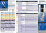
There are 16 4-pin DIP switches on the back side of the box for Port 1
to Port 8. 8 of them are mode switches (marked M1 to M8 for Port 1 to
Port 8 respectively) and the other 8 are terminator configuration
switches (marked T1 to T8 for Port 1 to Port 8 respectively).
Terminator Setting Switches
( T1~T8 for Port 1~8 )
RS232, 422, 485 Mode Switches
( M1~M8 for Port 1~8 )
(Bottom View)
1. Mode Switches (M1 to M8 for Port 1 to Port 8 respectively):
Each M1 to M8 has 4 switch pins which were marked their function
names as the following diagram. Pin 1 is to enable RS485 2 wire mode
(when ON), pin 2 enables RS485 4 wire mode (ON), pin 3 enables
RS422 mode (ON) and pin 4 enables Echo option (ON). Please refer to
the following table for more detail.
M1 to M8 DIP Switches:
ON
1 2 3 4
RS485-2W
RS485-4W
RS422
ECHO
3