1
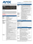
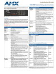
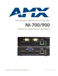
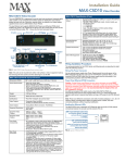
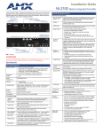
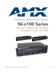
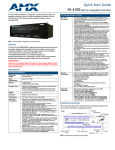
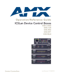
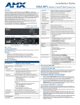
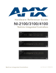
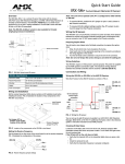
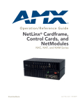
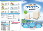
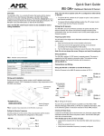
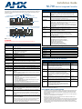
Installation Guide
NI-700 NetLinx Integrated Controller
The NI-700 (FG2105-70) is geared to meet the specific control and automation needs of a single
room environment, in which both price and functionality are the driving requirements. The NI-700 is
configured to control a limited number of video players, projectors, lights, thermostats, and other
electronic equipment.
IR Status LED
I/O Status LEDs
SERIAL Status LEDs
MASTER Status LEDs
IR RX LED
CONFIGURATION DIP Switch
PROGRAM port (DB9)
ID Pushbutton
(front)
PORT 2 (RS-232/422/485)
PORT 1 (RS-232/422/485)
ETHERNET 10/100 Port (RJ45)
12VDC Power connector
(rear)
IR RX connector
I/O connectors
AxLink connector / LED
IR connectors
NI-700 Specifications (Cont.)
IR (Port 3):
4-pin 3.5 mm mini-Phoenix IR/Serial port supports high-frequency
carriers of up to 1.142 MHz with the output in 3 formats: IR, Serial, Data.
Note: IR ports support data mode (at limited baud rates and wiring
distances).
AxLink Port/LED:
4-pin 3.5 mm mini-Phoenix (male) connector provides data and power to
external control devices.
Green AxLink LED indicates the status of the port.
ETHERNET
10/100 Port:
RJ-45 port for 10/100 Mbps communication. LEDs show communication
activity, connection status, speeds, and mode information:
• SPD (speed) - Yellow LED lights On when the connection speed is 100
Mbps and turns Off when the speed is 10 Mbps.
• L/A (link/activity) - Green LED lights On when the Ethernet cables are
connected and terminated correctly, and blinks when receiving Ethernet
data packets.
12VDC PWR:
Power Port: 2-pin 3.5 mm mini-Phoenix (male) connector.
Operating
Environment:
• Operating Temperature: 0° C (32° F) to 50° C (122° F)
• Operating Humidity: 20% - 85% RH
• Heat Dissipation (Typical): 11.5 BTU/hr
Included
Accessories:
•
•
•
•
2-pin 3.5 mm mini-Phoenix female PWR connector (41-5025)
4-pin 3.5 mm mini-Phoenix female connector (41-5047)
6-pin 3.5 mm mini-Phoenix female I/O connector (41-5063)
CC-NIRC IR Emitter
Other AMX
Equipment:
•
•
•
•
•
•
•
•
•
AC-RK Accessory Rack Kit (FG515)
CC-NIRC IR cables (FG10-000-11)
CC-NSER IR/Serial cables (FG10-007-10)
IRX-PP38 Plasma Proof IR Sensor (FG460)
IRX-DM+ IR Sensor (FG458-10 and FG458-11)
IRX-SM+ IR Sensor (FG455-01)
PMB Pole Mount Bracket (FG531)
STS, Serial To Screw Terminal (FG959)
Surface Mount Bracket Accessory (FG525)
FIG. 1 NI-700
ATTENTION!
Verify you are using the latest version of NetLinx Studio (available for download from
www.amx.com).
NI-700 Specifications
Dimensions (HWD):
• 1 9/16" x 5 9/16" x 5 1/8" (4.01 cm x 14.10 cm x 13.00 cm)
• RU: 1
Power Requirement:
• 280 mA @ 12 VDC
• Power requirements are usage dependant
Memory:
• 64 MB SDRAM (not upgradeable)
• 32 MB Flash chip (not upgradeable)
• 512 Kb of Non-volatile SRAM
Port Assignment and Functionality
NI-700 Port Assignments
Port
ICSP Port #
Serial Port #1
1
Serial Port #2
2
Microprocessor:
• 304 MIPS
IR/Serial Port
3
Weight:
• 1.30 lbs (0.59 kg)
I/O Port
4
Enclosure:
• Metal with black matte finish
IR RX Port
5
Certifications:
• FCC Part 15 Class B, CE, and IEC 60950
Front Panel Components
Ethernet Ports used by the NI Controller
PROGRAM Port:
RS-232 DB9 connector (male) can be connected to a DB9 port on a PC.
This port can be used with both Serial and NetLinx commands.
Ethernet Port Usage
Port type
Description
CONFIGURATION
DIP Switch:
8-position DIP switch sets the communication parameters for the Program
port.
FTP
The on-board Master has a built-in FTP server.
21/20 (TCP)
SSH
The SSH port functions using the same interface as Telnet but
over a secure shell where it uses SSL as a mechanism to
configure and diagnose a NetLinx system.
Note: SSH version 2 (only) is supported.
22 (TCP)
Telnet
The NetLinx Telnet server provides a mechanism to configure
and diagnose a NetLinx system.
23 (TCP)
HTTP
The Master has a built-in web server that complies with the
HTTP 1.0 specification and supports all of the required
features of HTTP v1.1. This port is used for unsecure HTTP
Internet communication between the web browser’s UI and the
target Master.
80 (TCP)
HTTPS/SSL
This port is used by a web browser to securely communicate
between the web server UI and the target Master.
443 (TCP)
ICSP
Peer-to-peer protocol used for both Master-to-Master and
Master-to-device communications.
1319 (UDP/TCP)
integration!
Solutions
This feature on the Master uses, by default, port 10500 for the
XML based communication protocol.
This port is connected to by the client web browser’s JVM
when integration! Solutions control pages are retrieved from
the on-board Master’s web server.
10500 (TCP)
IR RX LED (red):
Lights when IR data is being received via the rear IR RX port.
IR LED (red):
Lights during the transmission of IR or Serial data via the rear IR port.
I/O LEDs (yellow):
Light when the rear I/O channels 1 - 4 are active. LED indicator for each
I/O port reflects the state of that particular port.
SERIAL LEDs
(red and yellow):
Light when the rear DB9 Ports (1 & 2) transmit or receive RS-232, 422, or
485 data.
Note: These LEDs do not reflect changes in either the RTS or CTS when
hardware handshaking is used.
MASTER LEDs
• LINK/ACT (green): Lights when the Ethernet cable is connected and an
active link is established. This LED also blinks when receiving Ethernet
data packets.
• Status (green): Lights when the Controller is programmed and
communicating properly.
• Output (red): Lights when the Controller transmits data, sets channels
On and Off, sends data strings, etc.
• Input (yellow): Lights when the Controller receives data from button
pushes, strings, commands, channel levels, etc.
ID Pushbutton:
Sets the NetLinx ID (Device only) assignment for the device.
Rear Panel Components
PORT 1 /2:
Two RS-232/422/485 control ports use DB9 (male) connectors with XON/
XOFF (transmit On/transmit Off), CTS/RTS (clear to send/ready to send),
and 300 - 115,200 baud.
IR RX (Port 5):
4-pin 3.5 mm port connects up to 8 IRX-SM+ swivel mount or IRX-DM+
Decora mount IR receivers.
Note: The IR RX port functions using AMX IR codes (38 KHz and 455
KHz) and works ONLY with AMX IR Receivers such as the IRX-DM+ and
IRX-SM+.
I/O (Port 4):
4-channel digital I/O port for contact closure with each input being capable
of voltage sensing. Input format is software selectable with interactive
power sensing for IR ports.
Note: The I/Os are not dry closure; they are electronic switches that float
at 5V when Off. Therefore, they should not be expected to work in
situations that require true dry contact (or dry closure). The I/Os do work
with AMX PC1, PC2, UPC20 and UPC20+.
Standard Port #
Note: While the NI-700 is capable of receiving 8 and 9 bit characters, it cannot receive 7 bit, 1 stop
bit data from a serial device (ex: 9600,N,7,1).
RACK MOUNT SAFETY INSTRUCTIONS
•
•
•
•
•
If installed in a closed or multi-unit rack assembly, the operating ambient temperature of the
rack environment may be greater than room ambient. Therefore, consideration should be
given to installing the equipment in an environment compatible with the maximum ambient
temperature 50°C.
Installation of the equipment in a rack should be such that the amount of air flow required for
safe operation of the equipment is not compromised.
Mounting of the equipment in the rack should be such that a hazardous condition is not
achieved due to uneven mechanical loading.
Consideration should be given to the connection of the equipment to the supply circuit and the
effect that overloading of the circuits might have on over current protection and supply wiring.
Reliable earthing of rack-mounted equipment should be maintained. Particular attention
should be given to supply connections other than direct connections to the branch circuit (e.g.
use of power strips).
Installing into an Equipment Rack
Program Port Baud Rate Settings
Use the optional AC-RK Accessory Rack Kit (FG515) to mount the Controller into a standard 19"
equipment rack.
1.
Discharge the static electricity from your body by touching a grounded object.
2.
Align the front of the NI-700 through any of the three rectangular openings on the AC-RK.
3.
Use the included mounting screws to secure the unit’s faceplate to the AC-RK.
4.
Thread the cables through the opening in the equipment rack. Allow for enough slack in the
cables to accommodate for movement during the installation process.
5.
Reconnect all cables to their appropriate source/terminal locations. Verify that the terminal
end of the power cable is not connected to the a power supply before plugging in the 2-pin
power connector.
6.
Align the ends of the AC-RK with the screw openings along the sides of the equipment rack.
7.
Secure the AC-RK to the rack by using the four #10-32 screws (80-0186) and four #10
washers (80-0342) supplied in the kit.
8.
Apply power to the unit to complete the installation process.
The Configuration DIP switch is located on the front panel. Use this DIP switch to set the baud rate
for the Program Port, according to the settings shown in the following table. Make sure the baud rate
you set matches the baud rate on your PC's NetLinx COM Settings before programming the unit.
By default, the baud rate is set to 38,400 (bps).
Note: DIP switch 1 activates/deactivates the Program Run Disable Mode. DIP Switches 2,3, and 4
must remain OFF at all times.
Connections and Wiring
You will need a wire stripper and flat-blade screwdriver to prepare and connect the captive wires.
Note: Never pre-tin wires for compression-type connections.
1.
Strip 0.25 inch (6.35 mm) of insulation off all wires.
2.
Insert each wire into the appropriate opening on the connector (according to the wiring diagrams and connector types described in this section).
3.
Tighten the screws to secure the wire in the connector. Do not tighten the screws excessively
doing so may strip the threads and damage the connector.
Wiring a Power Connection
To use the 2-pin 3.5 mm mini-Phoenix connector with a 12 VDC-compliant power supply, the
incoming PWR and GND cables from the external source must be connected to their corresponding
locations on connector (FIG. 2).
1.
Insert the PWR and GND wires on the terminal end of the 2-pin 3.5 mm mini-Phoenix cable.
Match the wiring locations of the +/- on both the power supply and the terminal
connector.
2.
Tighten the clamp to secure the two wires.
3.
Verify the connection of the 2-pin 3.5 mm mini-Phoenix to the external 12 VDC-compliant
power supply.
PWR +
Power Supply
GND To the Integrated Controller
FIG. 2 2-pin mini-Phoenix connector wiring diagram (direct power)
FIG. 3 shows the pinout and wiring specification information for the rear RS-232/422/485 (DB9)
Device Ports (PORT 1 /2). These ports support most standard RS-232 communication protocols for
data transmission (Ports 1 & 2).
Position 6
Position 7
Position 8
OFF
ON
OFF
ON
38,400 bps (default)
OFF
ON
ON
ON
57,600 bps
ON
OFF
OFF
OFF
115,200 bps
ON
ON
ON
ON
RS-232
RS-422
RS-485
Pin 2: RX signal
Pin 1: RX -
Pin 1: A (strap to 9)
Pin 3: TX signal
Pin 4: TX +
Pin 4: B (strap to 6)
Pin 5: GND
Pin 5: GND
Pin 5: GND
Pin 7: RTS
Pin 6: RX +
Pin 6: B (strap to 4)
Pin 8: CTS
Pin 9: TX -
Pin 9: A (strap to 1)
Male
FIG. 3 RS-232/422/485 DB9 (male) connector pinouts
WARNING: When wiring the 422/485 connections, do NOT use pre-made 9-wire cable or connect
the wire in the cable to any connection that will not be used by the DB9 serial port. Only use wiring
that connects the needed pins.
Ethernet 10/100 Base-T Connector
A standard CAT5 Ethernet cable provides 10/100 network connectivity between the Integrated
Controller and the network (FIG. 4).
ETHERNET
10/100
L/A - Link/Activity LED lights
(green) when the Ethernet
cables are connected and
terminated correctly.
L/A
SPD
1.
2.
3.
SPD - Speed LED lights (yellow) when
the connection speed is 100 Mbps
and turns Off when the speed
is 10 Mbps.
Disconnect the power supply from the rear 2-pin PWR (green) connector.
Set DIP switch positions according to the information listed in the previous Baud Rate
Settings table.
Reapply power to the unit.
Preparing the NI-700 for Serial Communication
1.
2.
3.
4.
5.
6.
7.
8.
9.
10.
13.
14.
DB9 Serial Port pinouts (male connector)
7
6
Position 5
9600 bps
11.
12.
PORT 1/2 (DB9) Connectors
9
8
Baud Rate
Setting the Configuration (Program Port) DIP Switch
Preparing Captive Wires
5
4
3
2
1
Baud Rate Settings
Launch NetLinx Studio 2.x (default location is Start > Programs > AMX Control Disc >
NetLinx Studio 2 > NetLinx Studio 2).
Select Settings > Master Communication Settings, from the Main menu, to open the
Master Communication Settings dialog box.
Click the Communications Settings button to open the Communications Settings dialog.
Click the NetLinx Master radio button (from the Platform Selection section) to indicate you
are working with a NetLinx Master.
Click the Serial radio button (from the Transport Connection Option section) to indicate you
are connecting to the Master via a COM port.
Click the Edit Settings button (on the Communications Settings dialog) to open the Serial
Settings dialog and set the COM port parameters (used to communicate to the NetLinx
Master).
Click the OK button three times to return to the main application.
Right-click the entry in the Online Tree tab and select Refresh System.
Assign a System Value by using Diagnostics > Device Addressing from the Main menu.
Enable the Change System selection by clicking on it and then enter the current and new
System values.
Click the Change Device/System Number button and when finished click Done.
Select Tools > Reboot the Master Controller to access the Reboot the Master dialog, then
click Reboot to restart the Master and incorporate any changes.
Once the dialog replies with "Reboot of system complete", click Done and then click the
OnLine Tree tab in the Workspace window to view the devices on the System.The default
System value is one.
Right-click on the Empty Device Tree/System entry and select Refresh System to repopulate the list.
Configuring the NI-700 for Ethernet Communication
Before continuing, complete the COM port steps above.
1.
Connect an Ethernet cable to the unit’s rear Ethernet connector.
2.
Select Diagnostics > Network Address from the Main menu and enter the System, Device
(0 for a Master), and Host Name information.
3.
To configure the Address:
• Use a DHCP Address by selecting the Use DHCP radio button, then click the GET IP button
(to obtain a DHCP Address from the DHCP Server), click the SET IP Information button (to
retain the new address), and then finish the process by clicking the Reboot Master > OK
buttons.
• Use a Static IP Address by selecting the Specify IP Address radio button, enter the IP
parameters into the available fields, then click the SET IP Information button (to retain the
pre-reserved IP Address to the Master), and then click the Reboot Master > OK buttons to
finish the process.
4.
Repeat steps 1 - 5 from the previous section but rather than selecting the Serial option,
choose TCP/IP and edit the settings to match the IP Address you are using (whether Static or
IP).
5.
Click on the Authentication Required radio box (if the Master is secured) and press the
User Name and Password button to enter a valid username and password being used by
the secured Master.
6.
Click the OK button three times to return to the main application.
Additional Documentation
FIG. 4 Layout of Ethernet LEDs
Note: On NetLinx Masters (such as those aboard the NI-700), from within the Telnet or Terminal
applications; you can send the SET ETHERNET MODE command to assign the speed of your
Ethernet connection.
Sample NI-700 command:
Additional Documentation for the NI-700 is available at www.amx.com:
• Refer to the NI-700/900 Hardware Reference Guide for additional details on Installation,
Upgrading, and Wiring the NI-700.
• Refer to the NI Series NetLinx Integrated Controllers WebConsole & Programming Guide for
detailed configuration instructions.
SET ETHERNET MODE AUTO
The NI-700 only allows you to set the Ethernet mode to AUTO negotiate the Ethernet connection
speed. Using any of the other connection modes (10 Half/Full or 100 Half/Full) results in an error
message.
For full warranty information, refer to the AMX Instruction Manual(s) associated with your Product(s).
1/12
©2012 AMX. All rights reserved. AMX and the AMX logo are registered trademarks of AMX.
AMX reserves the right to alter specifications without notice at any time.
3000 RESEARCH DRIVE, RICHARDSON, TX 75082 • 800.222.0193 • fax 469.624.7153 • technical support 800.932.6993 • www.amx.com
93-2105-70
REV: D