1
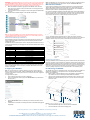
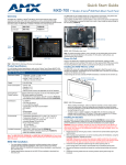
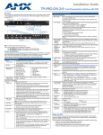
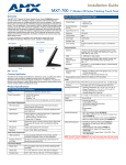
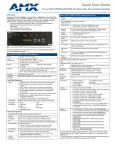
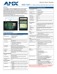
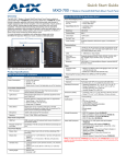
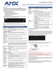
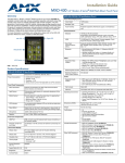
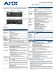
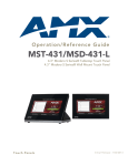
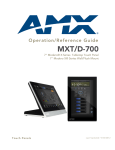
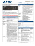
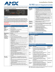
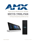
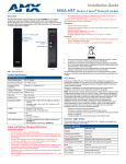
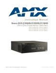
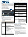
Installation Guide
MXA-MPL Modero X Series® Multi Preview Live
Overview
Status LED:
The MXA-MPL Modero X Series® Multi Preview Live (FG5968-10) is a touch panel
accessory that displays an HD video stream on Modero X Series Touch Panels when used in
conjunction with a high-definition (HD) Enova DVX All-In-One Presentation Switcher or
Enova DGX Digital Media Switcher. The MXA-MPL accepts digital video inputs over a DVI
Multi-Format connector and converts them to a video stream. The MXP-MPL also supports
all of the features of the MXA-MP, displaying up to 10 JPEG preview images on a Modero X
Series touch panel. The MXA-MPL makes it easy for users to identify quickly what is
currently being displayed by up to 10 source devices.
Note: For full functionality, the MXA-MPL may be used with the Enova series media
switchers and Modero X Series touch panels. The MXA-MPL may not be used with
previously released AMX touch panels or switchers.
For more information on installation and configuration, refer to the MXA-MP/MXA-MPL
Operation/Reference Guide, available at www.amx.com.
Front
Video Input
Diag Out
Ethernet In
Video Input LED:
Lights red when receiving video signals.
LAN LED:
Lights green when the LAN connection is enabled.
Panel LED:
Lights green when device is connected to a panel.
Video Output LED:
Lights red when sending a video stream to a touch panel.
Reset button:
Reboots the device when pressed.
Factory Reset button:
Resets the unit to factory defaults when pressed for at least 5 seconds.
Rear Components:
LAN
Panel
Video Outpu
Power
Status
Video Input
Reset
Factory Reset
Video Input:
DVI-I multi-format video input
Diag Out:
HDMI diagnostics output (720p only).
Audio In:
1/8th-inch mini-jack input (for use with non-HDMI audio only)
2-Pin Connector Output:
2-pin 3.5 mm Phoenix-style connector output, 12 Volts, 3 Amps
Ethernet In:
10/100 port, RJ-45 connector for Ethernet connection to network.
Ethernet Out:
10/100 port, RJ-45 connector for Ethernet connection to touch panel.
Power Input:
• IEC power cord connector
• 100-240V AC
• 47-63Hz
Operating Environment:
Rear
Audio In (not used)
2-pin Connector Output
Ethernet Out
(to Touch Panel)
Power Input
FIG. 1 MXA-MPL
1 9/16” x 8 1/4” x 7 3/16” (4 cm x 21 cm x 18.2 cm)
2.80 lbs (1.27 kg)
Certifications:
•
•
•
•
•
•
•
•
Included Accessories:
• MXA-MPL Installation Guide (93-5968-10)
• MIC AC Universal Power Cord (CA1090-131)
Other AMX Equipment:
•
•
•
•
•
•
•
Features
Product Specifications
MXA-MPL Specifications
Power Requirements:
• MXA-MPL only: 120VAC at 170ma (20W)
• MXA-MPL with touch panel: 120VAC at 410ma (50W)
Start-Up Inrush Current:
17.2A at 116.8VAC
Temperature (Operating): 32° F to 104° F (0° C to 40° C)
Temperature (Storage): 4° F to 140° F (-20° C to 60° C)
Humidity (Operating): 20% to 85% RH
Humidity (Storage): 5% to 85% RH
Power (“Heat”) Dissipation: 232 BTU/hr
Weight:
Use the MXA-MPL to preview a live video stream or snapshot of the content from a source device
before switching to that source.
Supports one (1) HD digital video stream or up to 10 preview images.
Updates all 10 preview images sequentially or one image continuously.
Streams digital video sources to a Modero X Series Touch Panel
Seamlessly interconnects between a Modero X Series Touch Panel and an Enova
DGX or Enova DVX.
•
•
•
•
•
Dimensions:
Common Applications
•
•
•
•
Toggles on/off green every 5 seconds if communicating to the
panel.(i.e.: the panel is configured to use the MXA-MPL).
UL
FCC Part 15 Class A
CE EN 55022 Class A and EN 55024
CB Scheme IEC 60950-1
IC
IEC/EN-60950
UL
RoHS
MPA-VRK, Rack Shelf 1RU 7.3" Depth (FG5968-30)
AC-SMB, Surface Mount Bracket Accessory (FG525)
CC-DVI-5BNCM, DVI to 5 BNC Male Cable 6' (FG10-2170-08)
CC-DVI-RCA3M, DVI to 3 RCA Male Cable 6' (FG10-2170-09)
CC-DVIM-VGAF, DVI to HD-15 Female Adapter (FG10-2170-13)
CC-DVI-SVID, DVI to S-Video Cable (FG10-2170-10)
CC-3.5ST5-RCA2F, 5-pin 3.5mm Phoenix-style to 2 RCA Female
Cable (FG10-003-20)
Rebooting the MXA-MPL
To reboot the MXA-MPL, press and hold the Reset button (FIG. 1) for one second.
Video:
Configuring the MXA-MPL
Video Streams:
Max Number of Active Video Streams: 1
Video Preview Images:
• Video Preview Image Format: JPEG (accessed over HTTP)
• Max Number of Video Preview Images:10
• Min Refresh Time of Preview Images: 2 sec
Configuring the MXA-MPL into a network requires modification of the device’s corresponding
NetLinx files via NetLinx Studio and the associated touch panel pages via TPDesign 4.
Documentation of the available commands may be found in the Modero X Series
Programming Guide, available at www.amx.com.
Video Input:
HDMI, DVI, RGBHV, S-Video, composite or component video
Resetting the MXA-MPL to Factory Defaults
Video Input Resolutions:
Video Input Resolutions supported by Firmware v2.1.28 or higher:
• HDMI/DVI: 1024 x 768p @ 60 Hz, 720 x 480i @ 60 Hz,
720 x 480p @ 60 Hz
• PAL: 576i, 576p @ 50 Hz
• NTSC: 480i, 480p @ 60 Hz
Video Input Resolutions supported by Firmware versions previous to
v2.1.28:
• HDMI/DVI: 640 x 480p @ 60 Hz, 800 x 600p @ 60 Hz,
1024 x 768p @ 60 Hz,1280 x 720p @ 60 Hz
• PAL: 576i, 576p@50 Hz
• NTSC: 480i, 480p@60 Hz
Video Input Resolutions not supported:
• 1280 x 768p @ 60 Hz, 1920 x 1080p @ 60 Hz
Video Output:
Up to 720p @ 30 fps over IP (Matches input resolution)
Communications:
10/100 port, RJ-45 connector with Ethernet/IP pass-through
Audio Input:
Unbalanced 1/8th-inch mini-jack connector (for use with non-HDMI
audio only)
Front Components:
Power LED:
Lights green when device is receiving power.
To reset the MXA-MPL’s configuration settings to its factory defaults:
1.
2.
Press and hold the Factory Reset button (on the front panel) for about 5 seconds.
The Power LED will blink three times. At this time, release the Factory Reset button.
To reset the MXA-MPL’s firmware from its current version to its factory default version:
1.
2.
Press and hold the Factory Reset button (on the front panel) for about 10 seconds.
At about the 5-second mark, the Power LED will blink 3 times. Keep holding the
Factory Reset button. At the 10-second mark, the Power LED will blink 7 times at a
faster rate. At this time, release the Factory Reset button.
Connecting the MXA-MPL to a Network
Since the MXA-MPL works to transmit HD video and images from an Enova switcher to a
Modero X touch panel, it needs to be connected between the switcher and the touch panel.
To connect the touch panel to the MXA-MPL:
1.
Insert the incoming network connection cable from the Enova switcher to the upper
Ethernet In RJ-45 connector (FIG. 1).
2.
If the touch panel is not panoramic (MXD/T-1000, MXD/T-700, MXD-430), connect an
outgoing Ethernet cable from the MXA-MPL’s Ethernet Out RJ-45 connector to an
AMX-certified high-power Power over Ethernet injector. Do not apply power until the
installation is complete.
3.
If the touch panel is a panoramic model (MXD/T-1900L-PAN or MXD/T-2000XL-PAN),
outgoing power to the touch panel may be supplied via the MXA-MPL’s 2-pin
connector output (FIG. 1) or through another source. Do not apply power until the
installation is complete.
WARNING: If using the MXA-MPL’s 2-pin connector for power for a touch panel, please refer
to the MXA-MP/MPL Operation Reference Guide for maximum cable lengths between the
MXA-MPL and the touch panel, based on cable gauge. Using a separate power source for
panoramic panel installations that require long cable runs is highly recommended.
4.
When the installation is complete, apply power to the MXA-MPL and to the touch
panel. Verify via the LEDs on the front of the device that it is receiving power and is
connected to the network.
5.
If the touch panel has not been configured to receive video signals from the MXA-MPL,
do so now.
FIG. 2 provides a basic installation diagram for the MXA-MP and MXA-MPL:
Note: If the MXA-MP is not connected to the touch panel, any attempts at enabling the panel
will fail, and the Breakout Box page will be blank other than the Breakout Box button.
Wall and Rack Installation
Some products are installed in areas of differing temperature and cooling methodologies.
These include products installed in walls, racks, cabinets, etc. Those areas may have
different temperatures and/or cooling approaches that must be taken into consideration to
maintain the product within the specified operating temperature.
FIG. 4 shows an AMX device installed in a wall with a filled volume (such as with insulation or
concrete), as well as with a closed volume (such as between studs in an otherwise finished
wall). The diagram shows how heat generated by the device or other devices may have no
way to escape, and may build up to levels that may affect device operation.
FIG. 2 Installation Diagram - MXA-MP and MXA-MPL
Note: For PoE-powered Modero X touch panels, the AMX-certified PoE injector must be
connected between the MXA-MPL and the touch panel. Use of a PoE switch in place of an
AMX-certified PoE injector is NOT recommended.
Maximum Power Cable Gauges and Distances
While most Modero X Series touch panels use Power Over Ethernet (PoE) for their power
needs, the panoramic Modero X Series touch panels use external power from an AMXcertified power source.
The MXA-MPL may be used as a power source for the panoramic touch panels, but only to
certain lengths determined by the cable gauge and the max distance between the device and
the touch panel.
FIG. 4 Heat convection in filled or closed volume, limited or no convection
In FIG. 5, the diagram displays an AMX device in a typical rack mounting, with full air
circulation around the front and back of the device. In this case, the main concern is with heat
building up between components, possibly to levels that may affect device operation.
Maximum Power Cable Gauges and Distances
Cable Gauge (AWG)
<16
16
17
18
19
20
21
22
23
24
>24
Maximum Distance (feet/meters)
Not recommended
24 feet (7.32 meters)
20 feet (6.10 meters)
15 feet (4.57 meters)
12 feet (3.66 meters)
10 feet (3.05 meters)
8 feet (2.44 meters)
6 feet (1.83 meters)
5 feet (1.52 meters)
4 feet (1.22 meters)
Not recommended
FIG. 5 Heat convection in rack-mounted devices
Installation Recommendations
Note: All power cable gauges are in AWG (American Wire Gauge).
When installing panoramic Modero X Series touch panels that exceed these cable lengths
between the MXA-MP/MPL and the touch panel, a separate AMX-certified power source
should be used instead.
During any installation, a lack of ventilation may produce conditions that may adversely affect
the device’s operation. In these circumstances, special care must be made to make sure that
temperatures within enclosed areas do not exceed the device’s maximum rated temperature.
Note: While the outside temperature of the device may be at or below its maximum operating
temperature, special care must be taken before and during installation to ensure that the
maximum operating temperature is not exceeded within wall or rack installation spaces.
Configuring the MXA-MPL
Rack Mounting the MXA-MP
Note: For more information on configuring a Modero X touch panel, please refer to the
Modero X Series Programming Guide, available at www.amx.com. After the MXA-MP is
connected to the network, the touch panel to which it is connected needs to be configured to
receive its signals.
To configure the touch panel:
1.
From the Settings page, select Connections & Networks.
2.
From the Connections & Networks page, select Breakout Box to open the Breakout
Box page (FIG. 3).
The MXA-MP may be put in a freestanding location, but the device may also be installed in a
standard rack. Installation in a rack requires the use of an (optional) MPA-VRK Rack
Mounting Tray (FG5968-30):
1.
Select a position on the Rack Mounting Tray for the installation. The Rack Mounting
Tray contains screw holes to allow single or double MXA-MP installations.
2.
Using the screws included with the MPA-VRK, install the screws to the bottom of the
MXA-MP through the Rack Mounting Tray (FIG. 6). Use four screws for each device,
one at each corner.
FIG. 3 Breakout Box Settings page
3.
4.
Press the Breakout Box button to enable the panel to receive information from the
MXA-MPL.
If the MXA-MPL is connected, the remaining information on the Breakout Box page will
self-populate.
Screws
MPA-VRK
FIG. 6 Installing two MXA-MPL devices in a Rack Mounting Tray
3.
4.
Connect the Rack Mounting Tray to the rack with the provided bolts.
Connect the MXA-MP to the network and apply power.
For full warranty information, refer to the AMX Instruction Manual(s) associated with your Product(s).
3/13
©2013 AMX. All rights reserved. AMX and the AMX logo are registered trademarks of AMX.
AMX reserves the right to alter specifications without notice at any time.
3000 RESEARCH DRIVE, RICHARDSON, TX 75082 • 800.222.0193 • fax 469.624.7153 • technical support 800.932.6993 • www.amx.com
93-5968-10
REV: H