1
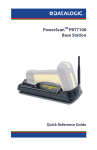
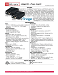
PowerScanTM Heated Holder
Installation, Assembly, and Operation
Installation
Ensure installation is performed by qualified service personnel
CAUTION
1.
Attach the bracket to your forklift using ¼-inch-diameter screws and lock washers (not provided).
Exercise extreme caution when you are working with the forklift battery. If handled improperly, the current from the DC
battery can cause injury or death.
DANGER
2.
Connect the Heated Holder power cable to your forklift battery as follows:
• Strip the holder BLACK (negative) wire and connect it to the negative battery terminal or to the chassis of the lift. Use a proper fastener to
ensure good electrical contact, such as a wire terminal (not provided).
• Strip the holder RED (positive) wire and connect it to the ignition switch of the forklift. Use a proper fastener to ensure good electrical contact, such as a wire terminal (not provided). If this connection is made directly to the battery’s positive terminal, provide an inline switch so it
can be turned off when not in use. If you use an inline switch, make sure that its current and voltage ratings are sufficient. See the Specifications on the following page for the three models.
Refer to your forklift owner’s manual, or contact your supplier or electrician for additional information or instructions.
• The Heated Holder is reverse-polarity-protected and will not function if connected backwards.
• Secure any excess cable slack to the forklift at one-foot intervals.
The Heated Holder is intended for direct-current (DC) connection only. Do not connect to a “line” or AC voltage source.
CAUTION
Assembly
1.
Assemble the bracket to the Heated Holder housing with the four mounting screws (see Figure 1). Depending on installation requirements,
you can mount the bracket as shown, vertically above the Heated Holder, or on the opposite side.
2.
Ensure that the Heated Holder is mounted with the front brushes towards the operator, and bottom brushes downward.
Front
Brushes
Holder
Housing
Forklift
Frame
Alternate
Bracket
Positions
Bracket
DOWN
Mounting Screws•
(4 places)
Power Cable & Strain Relief
Red
PWR
Black
GND
Figure 1. Heated Holder Mounting Diagram
Datalogic Scanning, Inc. • 959 Terry Street, Eugene, OR 97402 • (541) 683-5700
Page 1 of 2
Specifications
Heated
Holder
Physical
• Dimensions: 7.7 in. (19.6 cm) L
• 4.8 in. (12.2 cm) W
• 3.9 in. (9.9 cm) H
Environmental
Temperature
• Internal operating: Operating Solid State Control at 95º105ºF (35º-40ºC)
Front
Brushes
• Ambient operating: 22º to 104ºF (-30º to 40ºC)
• Storage: -40º to 158ºF (-40º to 70ºC)
Humidity (Ambient): 5% to 95% (non-conducting)
Scanner
Vibration: MIL-STD-810E. Method 514.4, Procedure 1
Approvals
CE, TUV
Electrical
Model
Number
721091900
721092000
721092100
Figure 2. Inserting the scanner in the Heated Holder
Input
Voltage
24 VDC
36 VDC
48 VDC
Input
Current
2.7 A
2.2 A
1.6 A
Power
Output
70 W
70 W
70 W
Power Cable:
• 10 ft. (3.05 m) L (unterminated)
• 18/2 Conductor cable
• Red wire: + positive lead
• Black wire: - negative lead
Patents: This product is covered by the following patent.5,508,505.
Operation
Do not put your fingers or hands inside the unit while it is on. Surfaces inside the unit are hot and may cause burns. Do
not use the Heated Holder as a handle; it is not intended to support human weight.
WARNING
1.
If the Heated Holder is connected to the ignition switch, turning the ignition switch on or off will control the heated holder. An LED illuminated from the inside of the holder indicates the power is on.
2.
Place the scanner into the holder (see Figure 2). Push the scanner through the front brushes as far as it will go. The brushes should return to
their original position.
820045314 (Rev B) - December / 2011
Page 2 of 2