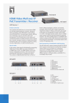
1
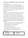
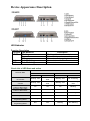
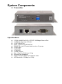
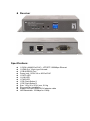
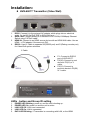
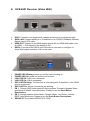
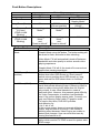
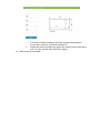
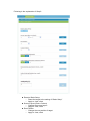
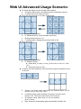
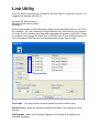
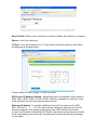
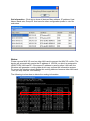
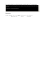
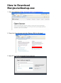
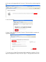
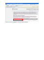
LevelOne User Manual HVE-6601T/6601R HDMI Video Wall over IP PoE Transmitter / Receiver Ver 1.0 Table of Contents HVE-660 series HDMI Video Wall over IP PoE T/R ......................................... 3 GETTING THE BEST RESULTS ..................................................................... 4 Device Appearance Description ................................................................... 5 System Components: ................................................................................... 6 Installation: ................................................................................................ 8 Following is the system setup figure for 3x3 video wall. ..........................................14 Installation Procedure (3x3) Using Web UI: ........................................................16 Web UI Advanced Setup Explanation: ...............................................................19 Web UI Advanced Usage Scenario: .................................................................22 Link Utility ................................................................................................24 How to Download Bonjoursdksetup.exe ............................................................28 HVE-660 series HDMI Video Wall over IP PoE T/R Product Overview The LevelOne HVE-660 Series is an innovative HDMI-over-IP Video Wall Distribution Solution. Designed with transmitting units (HVE-6601T) and receiving units (HVE-6601R), it is exceptionally scalable, offering any combination up to 9 x 9 matrix video wall arrangement. The HVE-660 Series riches video wall connectivity options to public premises such as sports bars, cinemas, transport stations, or highly demanded monitoring sites such as emergency response centers, security organization, or traffic monitoring units. How it works In the system, video signal is distributed by connecting HDMI-over-IP Video Wall Transmitter (HVE-6601T) to HDMI video source, via HDMI splitter if necessary. At each of displaying monitors, one receiving unit (HVE-6601R) is attached to complete the system. The solution is highly flexible that Point-to-Point or Point -to-Many topologies could be conveniently arranged. And to meet wider range of application requirement, Many-to-Many connection is also easily achievable and manageable through VLAN isolation with a managed network switch, where multiple video sources could be freely distributed to required monitors. The video gridding layout is modifiable with software utility provided. With advanced broadcasting technology the bandwidth is not heavily loaded to the number of displaying units. Key Features - Flexible and scalable HDMI 1080p Video Wall Broadcasting with Gigabit Ethernet - Multicasting and broadcasting architecture, no more bandwidth loading - Support NxN display array in a single Video Wall system. - Transmits an HDMI signal over one CAT5e/6/7 cable. - HDMI 1.3b and HDCP 1.2 compliant - Dual power input: 802.3af compliant PoE & DC5V - Up to 9 transmitters and 81 receivers possible in a single system - Built-in DIP switch to change Group ID and Utility for remotely - RS-232 Control Pass-Thru to control HDMI display from transmitter side Package Contents HVE-6601T: Power Adapter RS-232 Y-Cable CD Manual/Utility Quick Installation Guide HVE-6601R: Power Adapter CD Manual/Utility Quick Installation Guide GETTING THE BEST RESULTS Many factors influence the quality and reliability of an HDMI® signal distribution installation. The following are the main factors to consider, and basic precautions that will ensure the best possible performance. 1. Dedicated network. The HVE-650/660 Series is designed to operate on a dedicated Gigabit Ethernet network, not to be combined with other network traffic or with access to the internet. 2. Resolution tracking. Set up the source to output the best resolution that all TVs are capable of displaying. The HVE-650/660 Series supports 720p and 1080p. If some TVs in the network are not capable of accepting 1080p, the higher resolution sets may not be shown to their best advantage. 3. Source resolution and video/sound quality. Sources, such as satellite receivers or cable boxes, can output at low resolutions or deliver extremely compressed video material, yielding poor results. Consider the source when planning and troubleshooting your system. 4. Display devices. The perceived quality of the video image depends heavily upon the type and quality of the TVs or projectors used. High quality displays should be expected to produce a noticeably better image. 5. Distance between the transmitter and the receiver. Long distances are possible, but premium quality Cat 5e/6 cables are necessary for the longest runs. 6. Source and TV connection cables. Use short, premium HDMI cables; low quality cables are often unreliable. Always use good strain relief methods or locking cables to prevent cables from becoming loose over time. 7. Interference from nearby electrical devices It can have an adverse effect on signal quality. For example, older computer monitors often emit very high electromagnetic fields that can interfere with the performance of nearby video equipment. Device Appearance Description LED Behavior Function Description Function LED Behavior DATA Blinking On Off Link On/off/blinking PWR On/off/blinking Description Blinking while data transmission Ethernet link, no data transfer Ethernet no link, no data transfer Connect status for T or R Power status Check List of LED State and action LED State DEVICE State Host PWR Client LINK Off Blinking On PWR LINK Blinking On Off Blinking Power on, host and client not connect Blinking On Power on, host and client connect Press the host “PB” button to disconnect Press the client “PB1” button to disconnect Blinking On Off Blinking On Blinking On Off Blinking On On Off On Blinking On On On Off host power off Off Off On Blinking client power off On On Off Off Blinking Off→Blinking N/A N/A N/A N/A Blinking Off→Blinking Host Engineering Mode Client Engineering Mode System Components: Transmitter Specifications: 1 GIGA LAN(802.3af PoE): UTP/STP 1000Mbps Ethernet Port 1 HDMI IN: 19-pin type A female 1 DB-F RS232 Port Power : DC5V/1A or 802.3af PoE GROUP ID: 4-pin DIP switch able to set up 16 groups 1 DATA LED 1 LINK LED 1 PWR LED 1 RESET Button Size: 120 x 90 x 28 (H) mm, 0.8 kg Plug and Play Installation Support DVI with HDMI-to-DVI adapter cable LAN Bandwidth: 150Mbps for 1080p Receiver Specifications: 1 GIGA LAN(802.3af PoE) : UTP/STP 1000Mbps Ethernet 1 HDMI Out: 19-pin type A female 1 DB-M RS232 Port Power jack : DC5V/1A or 802.3af PoE 1 DATA LED 1 LINK LED 1 PWR LED 1 PB (Push Button)1 1 PB (Push Button)2 Size: 120 x 90 x 28 (H) mm, 0.8 kg Plug and Play Installation Support DVI with HDMI-to-DVI adapter cable LAN Bandwidth: 150Mbps for 1080p Installation: HVE-6601T Transmitter (Video Wall) 1. 2. 3. 4. DC5V: Connect it to the external AC adapter which plugs into an electrical outlet. Or via 802.3af PoE PSE to GIGA LAN port. GIGA LAN: Connect directly to a Receiver or to a GIGA(1000Mbps) Ethernet Switch using CAT5e/6 cable. HDMI IN: Connect to an HDMI source device with an HDMI M-M cable. Use an HDMI --> DVI adapter if the source is DVI. RS232: Used Y Cable to separate S0(RS232 port) and S1(Debug console port) for Video Wall system solutions. Y Cable P1: Connect to RS232 port of HVE-6601T. P2(S0): Connect to next device’s P3(S1) of Y cable. P3(S1): Connect to previous device’s P2(S0) of Y cable. LEDs , button and Group ID setting 1. 2. 3. 4. 5. POWER LED Blinking: power on and the unit is booting up. POWER LED On: power on and the unit is active. LINK LED Off: LAN is not connected. LINK LED On: LAN is connected. DATA LED Blinking: if Transmitter is connecting with LAN, or the HDMI 6. 7. 8. source is removed. DATA LED On: All the connections are working. PB : change Link / Unlink; Engineering Mode and Reset to default using this button. Please to see the Push Button Descriptions. GROUP ID: Set up the Transmitter’s group ID by adjusting the 4-pin DIP switch, ON means “1”, OFF means “0”, there are 16 groups available to set up. Multicast IP Address 255.0.0.XXX & 255.0.1.XXX, the XXX are resolved by the 4-pin DIP Switch on the Transmitter. 1. 2. 3. 4. 1. 2. 3. 4. 5. 6. 7. 8. 9. HVE-6601 Receiver (Video Wall) DC5V: Connect to the supplied AC adapter and plug into an electrical outlet. GIGA LAN: Connect directly to a Transmitter or to a GIGA(1000Mbps) Ethernet Switch using CAT6 cable. HDMI OUT: Connect to an HDMI display device with an HDMI M-M cable. Use an HDMI --> DVI adapter if the display is DVI. RS232: Connect to the RS232 port of the device you want to configure. In Video Wall system solutions it will not be used. POWER LED Blinking: power on and the unit is booting up. POWER LED On: power on and the unit is active. LINK LED Off: LAN is not connected. LINK LED On: LAN is connected. DATA LED Blinking: The Receiver is connecting with Transmitter, or the HDMI source is removed. DATA LED On: All the connections are working. PB 1 : Change OSD shows control/Column position; Firmware Upgrade Mode and Reset to default* using this button. Please to see the Push Button Descriptions. PB 2 : change between Video Mode / Graphic Mode ; Anti-Dither ; Update EDID* using this button. Please to see the Push Button Descriptions. GROUP ID: The default GROUP ID is “0000” Transmitter & Receiver IP Address The default setting is for “auto ip” mode and uses the 169.254.xxx.xxx private IP domain range. The IP of target TX/RX board is resolved by its hostname using DNS protocol. The RX’s HDMI GUI will display the RX’s IP address and the connected TX’s IP address. You can see the RX’s HDMI GUI by connecting it with power adapter and HDMI monitor only, without LAN cable. Configurations Push Button Descriptions : Short Press HVE-6601T(Host) PB NA Long Press (3 sec) NA Long Press on Boot (6~8 sec) (PWR & LINK Blinking) Long Press on Boot (PWR & LINK Blinking) Firmware Upgrade Mode* Button State HVE-6601R(Client) PB1 PB2 NA Video Mode/ Graphic Mode* OSD Shows/ Anti-Dither (Column position) (1/2/off)* Firmware Upgrade Update EDID* Mode* Firmware Upgrade Mode and Reset to default* Firmware Upgrade Mode and Reset to default* NA Button Feature Descriptions Video Mode/ Graphic Mode User can select to change between Video Mode / Graphic Mode using this button. The button setting will be saved to flash, and write-in after rebooting. Video Mode: FW will automatically trade-off between bandwidth and video quality to ensure smooth video playing experience. OSD Shows/(Column position) Anti-Dither (1/2/off) Update EDID Graphic Mode: FW will fix the trade-off to ensure best graphic/text viewing experience. User can select to change Column position using this button when after OSD shows up. Short press to switch column position when OSD shows up, long press and wait for OSD shows down to functions close. Anti-Dithering Mode is design to work with ATI graphic cards that provide dithering output. Dithering output is used to make coloring looks better than it's original color depth. It uses visual transient to create a half-tone effect. However, this presents great difficulty for Video Compression to maintain low bandwidth even if the source display seems static. Currently, we only see Dithering Output with ATI graphic cards. To resolve this issue, HVE-6601 provides Anti-dithering for 1 bit, 2 bit, or off. If the source content does not generate dithering output, and this feature is turn on. It will create a blocking effect because Video Engine are unable to detect pixel changes. User can avoid this issue by turning this feature to off. "Update EDID" feature is used for Multicast Mode to select which monitor/TV EDID is used for system wide EDID usage. During multicast setup, there maybe monitor/TV that has lower resolution. For example, 1 monitor/TV with 720p resolution with mostly 1080p solutions. Please select the monitor/TV with lowest resolution, to ensure all can be displayed correctly. For customer that are using 1 pair of Host/Client with Multicast mode, the end user must update EDID correctly. If not, it will cause many compatibility issue. Operation: Once the button event is triggered correctly at the client side, when system is setup correctly for Multicast. The selected EDID will be update to Host Side EEPROM. Firmware Upgrade Mode Reset to Default 1. Static IP: 192.168.0.88 2. User can connect to http://192.168.0.88 webpage for firmware update. 3. Firmware update file name will be: Host :webfwh.bin Client :webfwc.bin 1. Reset Any changes in SPI flash setup flag. 2. After Reset to Default and reboot cycle, will use default setting. Following is the system setup figure for 3x3 video wall. Note: ● If you use single Ethernet switch, the switch must support and enable IGMP snooping. And separate each row to different multicast group by using different 4-bits DIP switch number. Please visit Figure 2. Figure 2 ● ● ● ● ● 4bits DIP switch can all be 0000 or any number when each row is in different LAN (Ethernet switch) (Best fit in daisy-chain design) Please use Y cable of package provide to chain all hosts together through S0, S1 port. The chaining sequence is important and is shown in the Figure. S1 is the debug console port. S0 is the serial port originally used for RS232 over IP. Remember to connect the last host back to the first host. An video splitter is needed to split video source and feed to all hosts. The first host (host_r0 in Figure 1) will play the role as control portal and in charge of sending commands to the other hosts and clients. You must only issue commands through the control portal when performing video wall basic setup. The controller (PC) uses web browser(You can used Link Utility to press TV Wall butter was the same do.) to link to control portal’s web UI. If you don’t want to perform control through web interface. Basic System Concept: 1. HVE-6601 video wall solution is basically an extension of HVE-6601T/6601R’s multicast mode. 2. To achieve better video quality and resolve picture tearing issue, we divide the screen into rows. Each host in each row is responsible to capture the video screen of the row it belongs to. The solution is so called “multi-host” solution. “Single host” solution is also supported with drawbacks (lower video quality and tearing). To unify all kinds of video wall configuration, we take a system approach to separate the video wall layout into position layout and screen layout. Position layout means the physical position of each host and client. Every host and client will be assigned a unique position ID during “Basic setup”. In Figure 1, the position ID is indicated as r0c0, r1c2... Screen layout is used to tell HVE-6601T/6601R how to display its screen. For example, as 2x2 or 3x3. After “Basic setup” the position ID won’t change, so you can have a unique ID to address a device (for example r0c1) and ask this device to change it screen layout (for example from 3x3 to 2x2). In basic setup case, position layout equals to screen layout, but not necessary to. 3. 4. To follow the design concept of position layout and screen layout. User setup the position layout and ID only once during “Basic setup”. Any changes after “basic setup” should be performed in “advanced setup”, which select the control target by position ID and perform the advanced controls like changing screen layout. 5. To simplify the process of video wall configuration, we design the “control portal”. It is the first host of the first row of video wall. The control portal controls the other hosts and clients through the RS232 close loop chain. By using RS232 chain, hosts and clients can talk to each other even they are not in the same LAN. Installation Procedure (3x3) Using Web UI: 1. Prepare host(HVE-6601T) x 3 and client x 9(HVE-6601R). 2. Follow Figure 1 to construct the whole system. 3. Reboot all devices. Ensure that all remote displays and all network cables are connected correctly. (Video source is required at this step) 4. If the control PC (Windows OS) doesn’t install bonjour SDK yet, please install it. Google “bonjour SDK download” for the installation file or download it here: http://developer.apple.com/opensource/ . 5. Configure the control PC’s network setting to use 169.254.xxx.xxx IP domain with netmask 255.255.0.0. Or immediate running LinkTool.exe (copy from CD of package to control PC). 6. Open PC’s web browser (Google Chrome performs best. IE is not recommended). Link to the control portal (the first HVE-6601) by following web address http://last-gateway0000.local/vw/ . The 0000 part in above web address is mapping to the value of 4bits DIP switch. 7. If link success, user will see the web page as following : 8. Once user complete the 3 steps of “Basic Setup”, a basic video wall configuration is done. Step 1: Choose Wall Size. a. b. c. d. Step 2: Setup Column Position for Each Display. a. b. Set “Vertical Monitor Count” to 3. Set “Horizontal Monitor Count” to 3. Press “Apply” button. User will notice that all screens will refresh. If any row doesn’t response, check the connection of RS232 chain and retry. A OSD of a screen will shows up. User now starts to assign the column position of each client. If OSD doesn’t show up, try to switch back to step 1 and then step 2 again. There are 3 buttons in this step: i. “Next in Column” and “Next in Row” are used to select the client to be controlled. The chosen client will show up OSD. ii. “Change Column” is used to configure the column of the chosen client. Step 3: Bezel and Gap Compensation. i. This step is used to configure the bezel and gap compensation. If user don’t need this, just set all values to 0. ii. Follow the picture and input the size of the monitor used. Note that is unit is 0.1mm and the value MUST be integer. 12. Basic setup is completed. Web UI Advanced Setup Explanation: The “Advanced Setup” in web UI is used to do special effects which is not included in “Basic Setup”. For most of cases, “Advanced Setup” is never used. User can choose one or more targets to apply the changes to from Step 1. After the targets are selected, changes can be applied in Step 2. Following is the explanation of Step 2: Reset to Basic Setup ○ Reset the target to the setting of “Basic Setup” ○ Apply to: host, client Screen Layout (Row x Column) ○ Change the screen layout ○ Apply to: host, client Row Position ○ Change the row position of target ○ Apply to: host, client Column Position ○ Change the column position of target ○ Apply to: client Horizontal Shift ○ Horizontal shift target screen to left or right ○ Apply to: client ○ Unit: 8 pixels ○ Note: You can’t shift right when the screen touches the left edge Vertical Shift ○ Vertical shift target screen to up or down ○ Apply to: ■ host: in pixel unit ■ client: in 8 pixels unit ○ Note: You can’t shift down when the screen touches the top edge Horizontal Scale Up ○ Horizontal scale up target ○ Apply to: client ○ Unit: (1/column count) pixel Vertical Scale Up ○ Vertical Scale up target ○ Apply to: client ○ Unit: (1/row count) pixel Tearing Delay ○ Used under “single host mode” only. Used to avoid tearing. ○ Apply to: client ○ Unit: micro-second (us) ○ Note: the typical value is 10000~16000 Web UI Advanced Usage Scenario: To enable anti-dither function through web interface a. Complete “Basic Setup” and video signal is streaming to remote b. In “advanced setup” select all hosts From 3x3 setup change to 1x1 then change back a. Complete “Basic Setup” b. In “advanced setup”, select all hosts and clients. c. Change screen layout to 1x1. d. To change back, change screen layout back to 3x3 From 3x3 to 3x2 Complete “Basic Setup” In “Advance Setup”, ■ Select host_r0, host_r1, host_r2, r0c0, r0c1, r1c0, r1c1, r2c0, r2c1. ■ Set screen layout to 3x2. Create a 1x3 video wall which uses 3x3 screen layout and take the row 1 of the 3x3.: a. b. a. b. c. d. Create a 1x5 basic setup and assign the position layout as 1x5 with ID: host_r0, r0c0, r0c1, r0c2 In advance setup, select all hosts and clients. And set screen layout to 3x3. The screen will become 3x3’s first row. In advance setup, select host_r0, set row position ID as 1. Done. Note: Under this configuration gap compensation will take 3x3 layout. User can use v_shift and scale_up to do the fine tune. Use single host to create a 3x3 video wall: a. b. Connect host_r0 -> 3x3,and set position layout as 1x9 with position ID: host_r0, r0c0, r0c1,r0c2,r0c3,r0c4..., r0c8. Complete basic setup. In advance setup, select host_r0. Set screen layout to 1x1. c. d. e. f. Select all clients. Set screen layout to 3x3. Select r0c3, r0c4, r0c5, set row position to row 1. Select r0c6, r0c7, r0c8, set row position to row 2. Adjust “Tearing Delay Hack” to avoid tearing. NOTICES: 1. The output video signal timing will always be the same as input video timing. 2. Interlace mode is NOT supported. You will see wrong pictures under these timing. (1080i, 480i) 3 . N-rows X 1-Cols mode is NOT supported when horizontal resolution > 1280 pixels. Most of applications uses NxN scaling layout and pick one of the columns to form a Nx1 screen layout. So, this limitation is not a concern in real world application. 4. 1080P60Hz is preferred video timing which looks better after scaling up. 5. Multi-host video wall can achieve 60fps under 1080P60Hz, so there is no more concerns Regarding to "scrolling texts". 6. All monitors used in the same video wall are assumed to be the same in border and dimension. (Bezel and Gap compensation) Manually adjust via web UI is needed if the dimension is different. 7. Since video wall application typically uses the same monitors without special HDMI features (3D, multi-channel audio...), Just use a default EDID will be good to go. Link Utility The Link Utility is working with Widows XP Service Pack 2 or later O/S version. It is suggested to operate with O/S of : Windows XP Service Pack 3 Windows Vista Service Pack 2 Windows 7 Either at the website of http://developer.apple.com/networking/bonjour/ or the CD in the package, you may download bonjoursdksetup.exe and execute the program. You may find the following message after executing the program. HVE-6601 is able to configure and change the baud rate of RS232 over IP and Multicast group ID. This tool supports DNS protocol and programmed by Open Source code. Checked Box Check box : You may perform firmware update and other function keys. Search Device : show the devices hostname and MAX in the network for other function. F/W Upgrade : when click Firmware Upgrade, the Window IE is initializing for firmware upgrading. Reset Default : When click it, the device is reset to default, click Reboot to complete Reboot : click it for rebooting. TV Wall : when the firmware is for TV Wall mode,(Host Name prefix is HVE-6601), the webpage is showing below: Please refere to How to Setting TV Wall document. RS232 over IP Baudrate Setting : default Baud rate is at 9600bps. Other speed of 2400, 9600, 19200, 38400, 57600,115200, 230400 is available for selection. It has to be rebooted once the baud rate has been chosen. Multicast ID Setting : To configure Multicast Group ID, the value can be 0000, 0001, 0010,0011, …… 1111, etc. and it will be needed for rebooting once the ID has been selected. This setting is with priority and 4 DIP Switch is no function. In case, the ID shall be followed by DIP Switch, the device must be Reset to default. If the configuration goes incorrectly, the setting will indicate the following message for the status. Get Information : Click this to show all devices Mac address, IP address, Host Name, Baud rate, Group ID. And save for other configuration profile in .csv file sub-name. Notes: Please remove MAC ID used on other LAN card to prevent the MAC ID conflict. The device will automatically create the IP address of 169.254.x.x which is assigned to HDMI TX/RX LAN card IP. If the same IP address is used by other LAN card, the Windows will generate a routing table which may confuse the information access. To correct the situation, simply delete this routing table and remove other LAN card. Then you may use the Tool normally. The following to show how to delete the routing information: You need to delete the routing information circled by red line. The instruction is: Referencing : route delete 157.0.0.0 MASK 255.0.0.0 157.55.80.1 destination^ ^mask ^gateway How to Download Bonjoursdksetup.exe 1. Log-n the webpage of http://developer.apple.com/opensource/ 2. Drag down the web page and click “Bonjour SDK for Windows” 3. Apply ID or use the registered ID and password. 4. You may see the page while click “Join now”. Click the red line circled and get the link. 5. Click “Get Started” 6. Select “Create Apple ID” and click “Continue”. Follow the steps to complete the registration procedure. 7. You may get your Apple ID and password after registration completion. File this Apple ID and password on Step 3 and click “Sign in”. The page below will be seen. Click to execute the program or save for future installation.