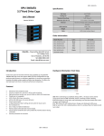
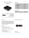
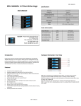
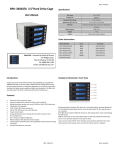
1
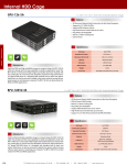
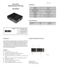
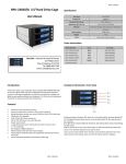
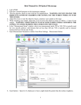
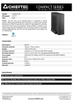
BPU‐124 4V2‐SS Mobile Backpla ane HDD C Cage BPU‐124V2‐SS Specificcation: Manual User’s M Hot Swap 4x2.55”HDD Cooling Fan 2x400mm SStandard Drive Baays 5.25” D Drive: 1 Diimension (W x H xx D) 5.75 x 1.65 xx 6.81 inches Material Aluminu um Body HDD Interface 2.5 SATAI/III/III / SAS I/II Weight 1.88 lbs Connector SStandard 15‐pin po ower and 7‐pin Data Indicators Power On: blue, HD Acccess: blue/red blinking Order IInformation: Model N Number: Color: UPC Code: BPU‐1244V2‐SS Black 8446813000017 iStarUSA – – Powered by iStarUSA i Group p 72 27 Phillips Drive e City of Indu ustry, CA 91748 8 Tel: ((888) 989‐1189 9 Email: [email protected] m Intro oduction: High leevel Raid and high availability storagge in a compact de esign, the BPU‐124 4V2‐ SS adds extra storage an nd hot‐swap capab bility to satisfy anyy application needss. PU‐124V2‐SS is con nstructed of light w weight and durable aluminum mate erial The BP with tw wo cooling fans to ensure best heat dissipation requirred for high perform mance 2.5” laptop p SAS/SATA drives. It is designed witth excellent front tto back veent airflow. Hard d drives can also be removed or added to the system withou ut turning off yourr system power or restarting your co omputer. The BPU‐ 124V2‐‐SS is an ideal solu ution for RAID and JBOD applications. Featu ures: FFrame: Aluminum m Construction In nterface: Suppo ort SAS, SATA‐I, SSATA‐II, SATA‐III FForm Factor: 1 x 5.25” Bay for 4 x 2.5” SAS or SATA Hard H D Drive(SSD) H High performancce transfer rate up to SAS & SATTA 6Gb/s SSupport RAID Fu nction (Note: e xtra SAS or SATA A RAID control ccard n needed ) P Plug & play, hot swappable SSupport 2.5” sin gle hard drive u p to 15mm thic kness in height W With 4Pin Powerr connector and 7Pin Signal con nector B Built‐in 2 X 4cm m(4020) cooling fan and the wiith mechanical lock Hardwaare Information: Front Vieew 1 3 5 6 2 4 Picture A A1: to A4 : HDD Tray A 5: Tray llocks A 6: Bluee color: HDD pow wer ON Blinkking in blue/redd color: HDD beiing accessed. o on the front trayy LLED for Power & HDD access BPU‐124V2‐SS BP PU‐124V2‐SS BPU-124V2-S SS BPU U‐124V2‐SS Hard dware Information: Rear V View BPU U‐124V2‐SS 7 10 8 11 9 12 13 14 15 18 Pictture C‐1 16 17 Picture P B Picture C‐2 Securi ty Lock B7: 155pin SATA powerr connector The Lockaable Design keep s the HDDs stayying inside the u unit and preventts HDDs B8 & B B9: 40mm Cooli ng Fan being takken out while thhey are running . B10, B B12, B14, B16: Primary Chann el (black) fo r SATA or SAS HDD H data p ports B11, B B13, B15, B17: Secondary Chan nnel (yellow) for SAS HDD data d ports & advanced use ers. *Note for Conn nections: A A. For SATA HD DDs, they are su pported by Prim mary ports (B10,, B12, B14, a nd B16) only. B B. For SAS HDDss, they are supportted by both Primary & Secondary channels. C C. Accesso ories: Dual channel SAS control card o or two systems (PC C) are needed if bo oth primary & s econdary ports need to be use d simultaneouslly. HDD LED Switch Indication desccription: B18: H a) Wh hen it is set to “X” Position, th he front LED do oes NOT blink while w HDD i s being accesse d. pin up when th he system powe er is In thi s case, the harrd drives will sp turned d on. b) Wh hen it is set to “O” “ position, fr ont LED blinkin g in blue/red while w the HD DD is being acce essed. In thi s case, the HDD D will not spin up until the SA ATA initial signaal is receivved. 1 maanual 2 keeys 4 SA ATA cables Neceessary screws iStarUSSAcare: We will hhelp you navigate our website to find the information that you needd. Go to www.istarrusa.com, and click on live chat bubble above thhe Search Bar. Our techhnicians are standing by to take yourr questions. Visit http://istaarusa.com/supportt/ , and you will reeceive a technical ssupport ticket to hhelp track your req quests from the beeginning to the end d. Or you can coontact us @ 888‐9989‐1189. (c) Th e default settingg for B18 (HDD LED Switch) is t o “O” position (HDD LED Enable). HDD D Installation n: A. FFor 2.5” SATA HD DD (SSD): P Put HDD onto th e tray as shown on Picture C‐1 and use the p provided screws to secure HDD on the tray one by one. B. diation Norm FCC and CE Rad FCC This equipment haas been tested and found to com mply with limits for Class B digital device pursuant to Part 15 of Fe ederal Communications Commiss sion (FCC) rules. CE This equipment haas been tested and found to com mply with the limits of the Europea an Council Directive on the appro oximation of the law of the memb ber states relating to electrom magnetic compatibility (89/336/E EEC) according to EN 55022 Classs B. FCC and CE Com mpliance Statement These limits are ddesigned to provide reasonable pprotection against frequency interrference in residential installation n. This equipment generates uses s and can radiate radio frequuency energy, and if not installedd or used in accordance with the instructions may cause harmful iinterference to radio communication. However, there is no guaranntee that interference will not occcur in television reception, which can be determined by turning the e equipment off and on. The user is encouraged to try and correct the interference by one or more of the following measures: Reorrient or relocate the receiving anttenna, Increase the separation be etween the equipment and thhe receiver, connect the equipme nt into an outlet on a circuit differrent from that to which the receivver is connected to. CAUTION! mmunications Commission warns the user that changes or modificcations to the unit not expressly a approved by the party responsible e for the The Federal Com compliance couldd void the user’s authority to operrate the equipment. FFor 2.5” SAS HDD D or HDD’s thickkness is more th an 10.5mm: Loo ose t he cover‐mountting screw and rremove the top cover. Mount th he SSAS HDD or the tthick HDD on th e open tray. ( Note: after SAS HDD installed, do not put on th he top cover (se ee P Picture C‐2.) putt the top cover i n a safe place, iin case you need d it n next time.) BPU‐124V2‐SS B BPU‐124V2‐SS