1
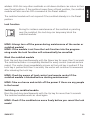
SWM1P
TM
IN WALL SHUTTER/SUNBLIND SWITCH
INBOUW ROLLUIK/ZONNEWERINGSSCHAKELAAR
USER MANUAL
3
GEBRUIKSAANWIJZING
25
20241/20080606 • SWM1P™ In wall shutter/sunblind switch
ALL RIGHTS RESERVED MARMITEK ©
2
© MARMITEK
SAFETY WARNINGS
• The wiring of your electrical installation is live (230 V) and extremely
dangerous. Never connect the module when plugged into the mains.
Always turn off the main switch before starting the installation.
• This product is for professional use and should be installed by a certified
installer.
• To prevent short circuits, this product should only be used inside and only in
dry spaces. Do not expose the components to rain or moisture. Do not use the
product close to a bath, swimming pool etc.
• Do not expose the components of your systems to extremely high
temperatures or bright light sources.
• In case of improper usage or if you have altered and repaired the product
yourself, all guarantees expire. Marmitek does not accept responsibility in
the case of improper usage of the product or when the product is used for
purposes other than specified. Marmitek does not accept responsibility for
additional damage other than covered by the legal product responsibility.
• This product is not a toy. Keep out of reach of children.
• Do not open the product: the device may contain live parts. The product
should only be repaired or serviced by a qualified expert.
• Automatic switching devices provide comfort, but can also be dangerous.
They can surprise people or can ignite clothing hanging over an electric heat
source. Please be careful and take appropriate measures to avoid accidents.
TABLE OF CONTENTS
HOW DOES MARMITEK X-10 WORK? ________________________________ 4
ADRESSES __________________________________________________ 4
SIGNAL RANGE ______________________________________________ 4
INSTRUCTIONS FOR USE ___________________________________________ 6
INTRODUCTION ______________________________________________ 6
FUNCTIONS _________________________________________________ 6
CONNECTION POSSIBILLITIES___________________________________ 6
LEGEND OF THE WIRING ______________________________________ 7
INSTALLING FOR A UP/DOWN CONTROL USING A
2 POSITION MOMENTARY SWITCH _____________________________ 7
INSTALLING USING A DOUBLE 2-WAY MOMENTARY
SWITCH - UP/DOWN, PRESENT AND LOCK ______________________ 10
PROGRAMMING ____________________________________________ 14
OPERATING INSTRUCTIONS ___________________________________ 17
TESTING AND REPLACING THE FUSE ___________________________ 21
FREQENTLY ASKED QUESTIONS _____________________________________ 23
TECHNICAL DATA ________________________________________________ 24
SWM1P™
3
HOW DOES MARMITEK X-10 WORK?
Marmitek X-10 components use the existing mains wiring to communicate
(using Marmitek X-10 signals). You can build a complete system using the
three different kinds of components of the Marmitek X-10 System:
1. Modules:
These components will receive Marmitek X-10 signals and
will switch or dim the attached lamp or appliance. Examples
of these modules are lamp modules and appliance modules.
These are available as build-in, micro, DIN rail and plug-in
modules.
2. Controllers: These components will transmit Marmitek X-10 signals and
thus will control the Modules.
3. Transmitters: Wireless components like remotes. The signals of these
components will be received by a controller with transceiver
functionality (IRRF7243, TM13 or CM15Pro). The Transceiver
will translate the signals into Marmitek X-10 signals on the
power line.
ADDRESSES
Up to a maximum of 256 different addresses can be preset. These are subdivided into a so-called HouseCode (A to P incl.) and a UnitCode (1 to 16 incl.).
The HouseCode can also be set on the controllers, so that the controllers and
modules become part of the same system. The address can be set either using
code dials or by pressing buttons, depending on the type of module.
The Marmitek X-10 System uses standard commands, which control all units
with the same HouseCode at the same time (e.g. all lights on, all off, etc.).
SIGNAL RANGE
Range of Marmitek X-10 signals over the Power Line and how to
increase the range.
The Marmitek X-10 System is based on power line communication. The range
of the Marmitek X-10 signals very much depends on the local circumstances.
On average the range is a cable length of 80 meters.
If you have difficulties with the range of your Marmitek X-10 signals,
please pay attention to the following facts:
1. When more than one phase is used for your electrical system, it is necessary
to couple these phases for the Marmitek X-10 signals. For coupling you can
use FD10 Phase Couplers/Filters. You only need to install a Phase Coupler/Filter
when your wall outlets and light switches are divided over more than one
phase (more than one group is no problem). For bigger buildings or longer
4
© MARMITEK
distances we advice you to use an active repeater instead of passive FD10’s.
2. It is possible that Marmitek X-10 signals are attenuated by devices and
lights which are connected to the power line. In a normal home situation this
effect is negligible (the Marmitek X-10 system is using active gain control to
eliminate the effects). However, it is possible that a particular device in your
house is attenuating the signals so much that the range of Marmitek X-10
signals is decreased significantly. When you have range problems, it is wise to
try to locate the device which is attenuating the signals simply by unplugging
devices from the power line, and testing the differences in range for your
Marmitek system. When e.g. your conclusion is that e.g. your computer
monitor is attenuating the signal, you can use a FM10 Plug-in Filter between
the power line and the monitor to eliminate the effects.
Known devices which can cause attenuation are:
PC Monitors
PCs with heavy internal power supplies
Old Televisions
Copiers
Fluorescent Lights
Gas Discharge Lamps (Energy Saving Lamps)
3. Some (old) devices are able to disturb the signal by transmitting noise on
the power line. Because the Marmitek X-10 signals are transmitted on 120
kHz, only noise on or near this frequency will have influence on the range.
When you use a FM10 Filter to connect this device to the power line, the
noise will be filtered.
4. The Marmitek X-10 protocol has several mechanism to avoid modules to
be switched on or off by other sources than your Marmitek X-10 Controllers.
However, it is possible that the Marmitek X-10 signals are disturbed by e.g.
baby phones which are in TALK mode (continuous transmission). When these
kind of signals are present on the power line it is possible that the Marmitek
X-10 signals will not come through.
5. The mains do not stop at the front door of your home. Everything that is
attached to mains nearby your home can have influence on Marmitek X-10
signals (e.g. heavy machinery). If you think that your system is influenced by
devices out of your house, it is advisable to install FD10 Phase Coupler/Filter
on each phase entering the house. These filters will block signals coming into
or going out of your house, but will also match the impedance for the mains.
SWM1P™
5
Hereby make your house Marmitek X-10 compatible for these units. The
FD10’s will not only filter but will also couple the phases (please see 1).
INSTRUCTIONS FOR USE
INTRODUCTION
Congratulations on purchasing the Marmitek shutter/sunblind module for
installation behind a momentary switch or in a junction box. This module is
suited for remotely and locally operating electric sunblinds, roll down shutters,
screens and, if desired, curtains. Because of its extremely small size, the
module can be installed behind plaster depth switches and wall outlets
(minimal depth of wall box 40 mm, recommended 50 mm). Universally
applicable: total freedom of choice for brand, colour and style of switches.
Attention! Marmitek build-in modules always have to be mounted in a
wall- or junction box.
Attention! Input only suited for 230 V live potential!
FUNCTIONS
• Driving of one 230Vac motor with at most 2.5 A.
• Reacts to ON, OFF, DIM+, DIM- and extended sunblind commands.
• One free programmable address A1...P16 for operation.
• One free programmable address A1...P16 for the Preset mode.
• Preset function for programming of a preference position.
• Possibility for controlling multiple SWM1P modules to one preference
position without
Marmitek CM15Pro Computer Interface using the Preset function.
• Local lock function for inhibiting the operation of the motor for instance
during maintenance.
CONNECTION POSSIBILITIES
Suitable for connecting:
• One 2-way momentary switch with 2 make-contacts (Up/Down function).
• One 2-way momentary switch with 4 make-contacts (Up/Down, Preset and
Lock function).
6
© MARMITEK
LEGEND OF THE WIRING
Installation wires:
= Brown (L or live)
= Blue (N or neutral)
= Black (hook-up wire)
= Yellow/Green (earth)
Input wires:
= Paar = Purple (input 1 motor control Up)
= White (input 2 motor control Down)
= Pink (input 3 Lock function)
= Grey (input 4 Preset function)
INSTALLING FOR UP/DOWN CONTROL USING A 2 POSITION
MOMENTARY SWITCH
MIND: Per SWM1P only one motor can be connected at a time. Never
connect two or more motors in parallel!
Connected to one 2-way momentary switch the sunblinds can be operated up
and down (see diagram below).
ATTENTION! The SWM1P has a thermal protection which protects the
module and motor against overheating. Combined with an external
heat source the thermal protection can be activated at unwanted
moments which makes the module temporary unresponsive. Therefore
do not mount the SWM1P in a wall box above a radiator or another
heat source or in a wall box which is exposed to direct (and intensive)
sunlight.
ATTENTION: First cut off the power before you start installing.
SWM1P™
7
Blue (N)
Brown
(L)
Black
P
Blue
(N)
Yellow/
Green
Black
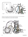
Figure 1.
• When present, remove the momentary switch from the wall box.
• Disconnect the wiring from the momentary switch.
• Pull a neutral wire (N) if this is not present.
PROG.
Figure 2.
SWM1P
Purple
White
Brown (L)
N
DN
UP
L
Black
Brown (L)
Blue (N)
P
Motor connection
Blue (N)
Yellow/Green
8
© MARMITEK
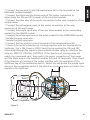
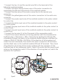
* Connect the live wire (L) and the neutral wire (N) to the terminals of the
Marmitek sunblind module.
* Connect the black and the brown wire of the motor connection to
respectively the DN and UP terminal of the sun blind module.
* Connect the blue wire of the motor connection to the wire connector of the
neutral wires.
* Connect the yellow/green wire of the motor connection to the wire
connector of the earth wires.
* Connect the purple input wire of the sun blind module to the momentary
contact for the ON/UP control.
* Connect the white input wire to the pulse contact for the OFF/DOWN control.
* Isolate the grey input wire.
* Isolate the pink input wire.
* Connect the live wire (L) to the P-terminal of the momentary switch.
* Check if the motor’s direction of running matches with the commands for
Up/Down. (Up = ON, Down = OFF) Check this by sending the ON and OFF
commands through the mains to the sunblind module using an interface (for
instance: PRU512, PRU256, CM15Pro). If the direction of running does not
match the commands sent, then switch the motor connection of the brown
and the black wire on the sunblind module (DN and UP terminals). Then check
if the direction of running of the motor matches with the operation of the
Up/Down key of the momentary switch. Switch the white and the purple input
wires on the momentary switch if the direction of running does not match the
operation for Up/Down.
P
PROG.
SWM1P
N
DN
UP
L
Figure 3.
SWM1P™
9
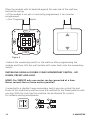
Place the module with its backside against the rear side of the wall box,
behind the wiring.
• If the module is not yet or incorrectly programmed, it can now be
programmed.
" See ‘Programming’ chapter.
Figure 4.
• Mount the momentary switch in the wall box after programming the
module and then click the push button with cover back onto the momentary
switch.
INSTALLING USING A DOUBLE 2-WAY MOMENTARY SWITCH - UP/
DOWN, PRESET AND LOCK
MIND: Per SWM1P only one motor can be connected at a time.
Never connect two or more motors parallel!
Connected to a double 2-way momentary switch you can control Up and
Down of the sunblind as well as move the sunblind to the Preset position with
one key. With the Lock key the sunblind can be blocked for control,
for instance during maintenance.
10
© MARMITEK
MIND: First cut off the power before you start mounting.
Blue (N)
Brown
(L)
Black
P
Blue
(N)
Yellow/
Green
Black
Figure 5.
If present, remove the momentary switch from the wall box.
* Disconnect the wiring from the momentary switch.
* Pull a neutral wire (N) if this is not present.
PROG.
Figure 6.
SWM1P
Purple
Grey
Pink
N
DN
White
UP
L
Black
Brown (L)
Blue (N)
Motor connection
P
Blue (N)
Yellow/Green
Brown (L)
SWM1P™
11
* Connect the live- (L) and the neutral wire (N) to the terminals of the
Marmitek sunblind module.
* Connect the black and the brown wire of the motor connection to
respectively the DN and UP terminal of the sunblind module.
* Connect the blue wire of the motor connection to the neutral wire
connector.
* Connect the yellow/green wire of the motor connection to the earth wire
connector.
* Connect the purple input wire of the sunblind module to the pulse contact
to control Up.
* Connect the white input wire of the sunblind module to the pulse contact
to control Down.
* Connect the grey input wire of the sunblind module to the pulse contact to
control Preset.
* Connect the pink input wire of the sunblind module to the pulse contact to
control Lock.
* Connect the live wire (L) to the P-terminal of the momentary switch.
* Check if the motor’s direction of turning matches with the commands for
Up/Down (Up = ON, Down = OFF). Check this by sending the ON and OFF
commands through the mains to the sunblind module using an interface (for
instance: PRU512, PRU256, CM15Pro). If the direction of turning does not
match the sent commands, then switch the motor connection of the brown
and the black wire on the sunblind module (DN and UP terminal). Then check
if the direction of turning of the motor matches with the operation of the
Up/Down key of the momentary switch. Switch the white and the purple input
wires on the momentary switch if the direction of turning does not match the
operation for Up/Down.
PROG.
SWM1P
P
N
DN
UP
L
Figure 7.
12
© MARMITEK
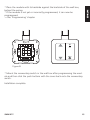
* Place the module with its backside against the backside of the wall box,
behind the wiring.
* If the module is not yet or incorrectly programmed, it can now be
programmed.
" See ‘Programming’ chapter.
Figure 8.
* Mount the momentary switch in the wall box after programming the module and then click the push buttons with the cover back onto the momentary
switch.
Installation complete.
SWM1P™
13
PROGRAMMING
MIND: Switch on power before you start programming. Avoid touching
live parts!
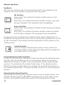
In programming mode the addresses of inputs 1 and 2 (motor address) and
of input 4 (Preset address) can be programmed individually. Also the end positions of the motor need to be programmed to make them match the position
values of 0% and 100%.
Programming
For programming the module you have to follow the 5 steps below.
1. Switch module to programming mode.
2. Send the motor address.
3. Program the end positions of the motor.
4. Program the Preset address (optional).
5. Leave the programming mode.
These steps are explained.
1. Switch to programming mode
To program the sunblind, it has to be set to the programming mode as follows:
* Push the programming button for at least 3 seconds, see figure 9, when you
release the button the red LED will illuminate.
* Use the automatic programming function of the PRU512.
For this see the manual of the PRU512
P
PROG.
SWM1P
N
DN
UP
L
PROG.
Figure 9. Activating and cancelling the programming mode.
14
© MARMITEK
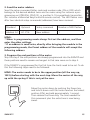
2. Send the motor address
Send the setup command (letter code and number code, ON or OFF) which
belongs to the desired address twice via the mains using for instance a programming unit (PRU256, PRU512), or another X-10-compatibele transmitter
(for instance a Marmitek EasyControl 8 remote control). The LED flashes once
after two identical setup commands (addresses) have been received.
Standard
Optional
Setup command
Number of LED flashes
Address A1
A1..P16
New address
1
MIND:
* When in programming mode always first set the address, and then
enter the other settings.
* If an address is send twice, directly after bringing the module in the
programming mode, the Preset address of the module will accept the
following address.
3. Program the end positions of the motor
Skip this step if the end positions are already programmed into the SWM1P and
these positions need to remain unchanged. In that case move on to step 4.
If the SWM1P is programmed for the first time the limits need to be set. To do
this the following steps need to be followed:
MIND: The motor needs to be in the upper position (all the way up,
100%) before starting with the next step. Move the motor all the way
up with the up-key if this is not yet the case.
Move the motor down by pushing the Down key
and hold it down until the motor reaches the lowest
position (0%) and add approximately 1 second.
Then release the Down key. The time needed for
this movement plus the extra time is now being
saved.
SWM1P™
15
Move the motor up by pushing the Up key and hold
it down until the motor reaches the upper position
(100%) and add approximately 1 second. Then
release the Up key. The time needed for this
movement plus the extra time is now being saved.
Above mentioned steps can be repeated multiple times. Each new
movement will be saved. If you release the button too early, then you
need to move the motor fully up or down first and then repeat the
steps mentioned above in random order.
4. Programming the Preset address
If the Preset address needs to be programmed to a different address than
the standard address (this is the first following address of the motor) then
the set-up command of the desired address needs to be send twice via the
mains using for instance a programming unit (PRU256 of PRU512), or another
X-10-compatibele transmitter (for instance a Marmitek EasyControl8 remote
control).
Standard
Optional
Setup command
Number LED flashes
Preset address
A2
A1..P16
New address
2
Programming of the Preset position is described in chapter ‘Operating
instructions’.
5. Leave programming mode
* Press the programming button once for a short period of time; the red LED
now is off, or wait 60 seconds what automatically cancels the programming
mode.
MIND: If within 60 seconds no setting command is received,
the module will automatically return to the programming mode.
16
© MARMITEK
OPERATING INSTRUCTIONS
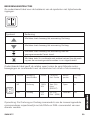
See table below for the meaning of the symbols with accompanying inputs.
Symbol
Control
With this key the sunblind moves UP
With this key the sunblind moves DOWN.
With this key the sunblind moves to the programmed
Preset position.
With this key (In combination with the other keys) the
sunblind module can be switched on or off.
The table below shows the relations between the different moves of the motor
and commands with the position of the roll-down shutter or sunblind.
Symbol
Module
Movement
terminal
Position
Commands
position
Roll shutter
position
Sunblind
UP
up
100%
X%
on (On)
dim+
(BRIGHT)
open
in
DN
down
0%
X%
off (Off)
dim - (DIM)
closed
out
Note: The Up and Down commands of the sunblind module correspond
respectively with the DIM+ and DIM- commands of a dimmer module.
SWM1P™
17
Manual operation
Up/down
With the Up and Down key of the momentary switch the sunblind can be
moved to the correct position using short and long pulses.
Up function
Press briefly: The sunblind (roll-down shutter) moves in (up),
to the end.
Press long: The sunblind (roll-down shutter) moves in (up) until
the key is released. The movement stops immediately.
Down function
Press briefly: The sunblind (roll-down shutter) moves out (down),
to the end.
Press long: The sunblind (roll-down shutter) moves out (down)
until the key is released. The movement stops immediately.
As soon as the key is released the sunblind module sends a Marmitek X-10
EXTENDED command via the mains with its new position, possibly with an ON
or OFF command if the sunblind reached respectively the 0% position or the
100% position.
Preset function
With the Preset a desired preset position of the sunblind or
roll-down shutter can be saved and afterwards be recalled with
one simple push on the button.
Programming the Preset position
As soon as the sunblind or roll-down shutter has reached the desired position
(operate with UP and DN key) this can be saved by holding the Preset key
down for more than 5 seconds. The current position will be saved as Preset
position. The module has 25 possible Preset values. If the desired position
differs from these possible values, the module will round off this position to
the nearest possible value. This value can differ at most 4 % from the desired
position.
Operating the Preset function
By pressing the Preset key the sunblind moves to the set Preset position. The
sunblind module sends an EXTENDED command via the mains with its new
position. The sunblind module also sends an ON command at its Preset
18
© MARMITEK
address. With this any other sunblinds or roll-down shutters can return to their
own Preset position. If the sunblind comes from a Preset position, the sunblind
module will also send an OFF command at the Preset address.
The sunblind module will not respond if the sunblind already is in the Preset
position.
Lock function
During for instance maintenance of the sunblind or painting
near the sunblind, the Lock key can temporary block the
sunblind module.
MIND: Always turn off the power during maintenance of the motor or
sunblind module!
MIND: If the module is set from the Lock function into the programming mode the Lock function will automatically be cancelled.
Block the sunblind module
Push the Lock key simultaneously with the Down key for more than 5 seconds.
The sunblind actuator is completely blocked for every control (manual and via
mains). The motor stops immediately as soon as the Lock key is pushed. If the
Lock key is pushed less than 5 seconds, the motor will continue its movement
after releasing the Lock key.
MIND: Check by means of local control and remote control if the
sunblind module is blocked before starting maintenance!
MIND: Take no chance and switch off the power if there are any people
in the house!
Switching on sunblind module
Press the Lock key simultaneously with the Up key for more than 5 seconds.
The sunblind module works as usual again.
MIND: Check if the sunblind can move freely before you cancel the lock
mode!
SWM1P™
19
Remote operation
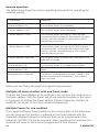
The table below shows the various operating commands for operating the
sunblind module.
Command
Reaction
<Motor address> On
The sunblind moves up completely.
< Motor address > Off
The sunblind moves down completely.
< Motor address > DIM+
The sunblind moves one step up. With multiple
consecutive DIM+ commands the sunblind will keep
moving until the commands stop or the sunblind
reaches the end position.
< Motor address > DIM-
The sunblind moves one step down. With multiple
consecutive DIM- commands the sunblind will keep
moving until the commands stop or the sunblind
reaches the end position.
< Motor address> Extended
The sunblind moves to the position indicated in the
extended command.
<Preset address> On
The sunblind moves to its saved Preset position.
<Preset address> Off
None.
<Preset address> Extended
The value in the extended command is saved in the
sunblind module as Preset position. The sunblind
does not move
Below you can find some practical programming examples.
Multiple roll-down shutters with one Preset mode
Program the Preset address of all sunblinds in for instance the living room to
the same address. With the Preset key of any sunblind modules in this room
or by means of sending the Preset address ON via a Marmitek interface all
sunblinds can be set to the Preset mode simultaneously.
Multiple Presets for one sunblind
If you need a different Preset position in the morning than in the afternoon,
you can program this position in advance at the Preset address with the
extended command using the scenario’s that can be programmed in the
Marmitek CM15Pro Computer Interface. When operating the Preset key the
sunblind will move to the position programmed at that moment.
20
© MARMITEK
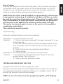
Loss of power
If during the movement of the motor the power fails, the motor will stay in
this position when the power returns to the sunblind module. At the first
operation to an in-between position the motor will first take a calibration
move up or down before moving to the position desired.
MIND: Both the motor and the SWM1P are protected by a thermal protector against overheating. A sunblind or roll-down shutter can never
be used for more than 4 minutes on end. If the motor is used for more
than 4 minutes due to some unforeseen circumstance, the protection
of the motor or the SWM1P will activate and the motor will stop.
The motor can be used again as soon as the motor or the module is
completely cooled down.
This could take several minutes!
Troubleshooting
Follow the checklist below in case of any problems.
Observation: The sunblind does not work.
Checklist:
1. Check in the meter cupboard if all power is present. If so, go
to the next step.
2. Press the Lock key and the Up key simultaneously for more
than 5 seconds. Go to the next step if this does not solve the
problem.
3. Check if the led on the sunblind module flashes.
4. Check the fuse.
Observation: The sunblind does not respond to the Preset key.
Checklist:
1. The sunblind is already in the Preset mode or the key is
pressed longer than 5 seconds.
2. Check is the Lock function is active.
TESTING AND REPLACING THE FUSE
Testing of the function of the fuse (type TR5 -4AT)
Disconnect the load (motor) from the SWM1P. Then measure the voltage on
the output terminals with a voltmeter. If there is no voltage on both the UP
and the DN terminal, than the fuse is defect.
MIND: In case of a blown fuse the programming LED is still flashing.
SWM1P™
21
Changing a defective fuse for SWM1P
Changing a fuse can be done without opening the module! (When you open
the module, the warranty expires).
MIND: Switch off the power so the module is free of power before you
continue.
Remove the film on top of the fuse and then carefully remove the fuse from
the module with a set of pointed pliers (see figure 10).
2
PROG.
PROG.
SWM1P
N
DN
UP
SWM1P
L
N
DN
UP
L
3,3 mm
Figure 10.
Change the fuse with a fuse of the following types (when using different
types of fuses warranty expires):
Survey of allowed module fuses for Marmitek SWM1P module.
Supplier fuse
Description
Littelfuse
LT-5 ALg
Bussman
ETF Radial Lead Micro
Fuse
ELU
Subminiature fuse links
Wickmann
Subminiatur fuse No
372.TR5
Bel fuse
Time Lag Radial Lead
Micro Fuse
22
© MARMITEK
FREQENTLY ASKED QUESTIONS
What is the reason for modules to switch on/off spontaneously?
It is possible that a Marmitek X-10 System is installed at one of your
neighbours using the same House Code. To solve this problem try to change
the House Code of your system, or have FD10 Phase Coupler/Filter installed at
your incoming mains.
My modules will not respond to my controller.
Make sure that the House Code on all Modules and Controllers are set to the
same House Code (A .. P).
My modules will not react to my remote / sensor.
When you use a remote or sensor, you should have at least one TM13
Transceiver or Marmitek X-10 Security Console installed in your house. These
components will translate the radio signals to the Marmitek X-10 signal on
the power line. Using several remotes and sensors, you only need one central
transceiver.
Am I able to increase the range of my remotes by using more Transceivers?
Yes, you can use more than one TM13 Transceiver in your home when the
range of your remotes is not sufficient. The TM13 is using so called collision
detection to prevent signals to be disturbed when more than one TM13 is
transmitting. TM13’s will wait for a quite power line before transmitting their
data. To prevent your Marmitek X-10 System to become slow or to prevent
dimming from becoming less smooth, make sure that the TM13 units are
placed as far away from each other as possible.
Do you still have questions? Please check out www.marmitek.com for
more information.
SWM1P™
23
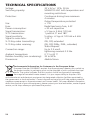
TECHNICAL SPECIFICATIONS
Voltage:
Switching capacity:
Protection:
Use:
Fuse:
Power consumption:
Signal transmission:
X-10 transmission:
Signal sensitivity:
Signal to noise ratio:
X-10 Key codes transmitting:
X-10 Key codes receiving:
Connection range:
Ambient temperature:
Relative humidity (non condensing):
Dimensions:
30 V AC+/- 10%, 50 Hz
500W/230 VAC with temperature and
mounting restrictions.
Continuous driving time maximum
4 minutes.
Output temperature protected.
<1W
Radial lead micro fuse, 4 AT.
< 30 mA capacitive
> 5 Vpp in 5 7 at 120 kHz
1 pulse at 0° and 180°
5 mVpp...6 Vpp at 120 kHz ± 4 kHz
1.35 : 1
ON, OFF, extended
ON, OFF, DIM+, DIM-, extended,
Status Request
Up to 2.5 mm2,
tightening moment 0.5 Nm
0 °C to 40 °C
30 to 90%
46x46x16mm.
Environmental Information for Customers in the European Union
European Directive 2002/96/EC requires that the equipment bearing this symbol on
the product and/or its packaging must not be disposed of with unsorted municipal
waste. The symbol indicates that this product should be disposed of separately
from regular household waste streams. It is your responsibility to dispose of this
and other electric and electronic equipment via designated collection facilities appointed by
the government or local authorities. Correct disposal and recycling will help prevent potential
negative consequences to the environment and human health. For more detailed information
about the disposal of your old equipment, please contact your local authorities, waste disposal
service, or the shop where you purchased the product.
24
© MARMITEK
VEILIGHEIDSWAARSCHUWINGEN
• Op de bedrading van uw elektrische installatie staat levensgevaarlijke 230V netspanning. Sluit de module nooit onder spanning aan. Schakel de hoofdschakelaar uit
voordat u met de installatie begint.
• Dit product is bestemd voor professioneel gebruik. Installatie dient te geschieden
door een erkende installateur.
• Om kortsluiting te voorkomen, dient dit product uitsluitend binnenshuis gebruikt
te worden, en alleen in droge ruimten. Stel de componenten niet bloot aan regen of
vocht. Niet naast of vlakbij een bad, zwembad, etc. gebruiken.
• Stel de componenten van uw systeem niet bloot aan extreem hoge temperaturen
of sterke lichtbronnen.
• Bij oneigenlijk gebruik, zelf aangebrachte veranderingen of reparaties, komen alle
garantiebepalingen te vervallen. Marmitek aanvaardt geen productaansprakelijkheid
bij onjuist gebruik van het product of door gebruik anders dan waarvoor het product
is bestemd. Marmitek aanvaardt geen aansprakelijkheid voor volgschade anders dan
de wettelijke productaansprakelijkheid.
• Dit product is geen speelgoed. Buiten bereik van kinderen houden.
• Het product nooit openmaken: de apparatuur kan onderdelen bevatten waarop
levensgevaarlijke spanning staat. Laat reparatie of service alleen over aan deskundig
personeel.
• Behalve gemak kan automatisch schakelen ook gevaar met zich meebrengen.
Zo kunnen anderen verrast worden, of kan kleding welke over een elektrische
warmtebron hangt in brand raken. Wees hier altijd op bedacht en neem afdoende
maatregelen ter voorkoming.
INHOUDSOPGAVE
HOE WERKT MARMITEK X-10? ____________________________________
ADRESSERING ______________________________________________
BEREIK VAN SIGNALEN _______________________________________
GEBRUIKSAANWIJZING __________________________________________
INTRODUCTIE ______________________________________________
FUNCTIES __________________________________________________
AANSLUITTOEPASSINGEN ____________________________________
LEGENDA VAN DE AANSLUITDRADEN __________________________
MONTAGE VOOR OMHOOG/OMLAAG BEDIENING OP
EEN 2 VLAKS PULSDRUKSCHAKELAAR _________________________
MONTAGE OP EEN 2 VLAKS PULSDRUKSCHAKELAAR OMHOOG/OMLAAG, PRESET EN LOCK _________________________
PROGRAMMEREN ___________________________________________
BEDIENINGSINSTRUCTIES _____________________________________
TESTEN EN VERVANGEN VAN DE ZEKERING _____________________
VEEL GESTELDE VRAGEN _________________________________________
TECHNISCHE GEGEVENS _________________________________________
SWM1P™
26
26
26
28
28
28
28
29
29
32
36
39
44
45
46
25
HOE WERKT MARMITEK X-10?
De componenten uit het Marmitek X-10 programma communiceren met
elkaar via het bestaande lichtnet (door middel van Marmitek X-10 signalen).
Het programma bestaat uit drie soorten onderdelen:
1. Modules: Deze ontvangen de Marmitek X-10 signalen en schakelen of
dimmen de aangesloten belasting.
2. Controllers: Deze zenden de Marmitek X-10 signalen en besturen de
Modules.
3. Zenders: Dit zijn draadloze onderdelen zoals afstandsbedieningen. De
signalen hiervan worden ontvangen door een Controller met
Transceiver functie (IRRF7243, TM13 of CM15Pro). De signalen
worden door de Transceiver op het lichtnet gezet.
ADRESSERING
Er kunnen tot maximaal 256 verschillende adressen worden ingesteld. Deze
zijn onderverdeeld in een z.g. HuisCode (A t/m P) en UnitCode (1 t/m 16). De
HuisCode is ook instelbaar op de Controllers zodat Controllers en Modules tot
hetzelfde systeem gaan behoren. Het adres kan door middel van codewieltjes,
of indrukken van toetsen ingesteld worden, afhankelijk van het type module.
Het Marmitek X-10 Systeem bevat standaard commando’s waarbij alle units
binnen dezelfde HuisCode tegelijkertijd worden aangestuurd
(bv. alle verlichting aan, alles uit, etc.).
BEREIK VAN SIGNALEN
Bereik van Marmitek X-10 signalen over het lichtnet en dit bereik vergroten.
Het Marmitek X-10 Systeem is gebaseerd op communicatie via het bestaande
lichtnet. Het bereik van de signalen over het lichtnet is erg afhankelijk van de
plaatselijke situatie. Een aardig gemiddelde van het bereik is echter een kabellengte van 80 meter.
Bij problemen met het bereik van Marmitek X-10 signalen zijn de
volgende factoren van belang:
1. Wanneer er meerdere fasen in huis worden gebruikt, kan het nodig zijn
om deze fasen te koppelen voor Marmitek X-10 signalen. Dit koppelen
kunt u doen door het gebruik van FD10 Fase Koppelfilters en is nodig als
wandcontactdozen en verlichtingspunten daadwerkelijk verdeeld zijn over
meerdere fasen (meerdere groepen is geen enkel probleem voor het Marmitek
X-10 signaal). Voor grotere panden adviseren wij het gebruik van een actieve
3 fasen repeater in plaats van Fase Koppelfilters.
26
© MARMITEK
2. Marmitek X-10 signalen kunnen worden gedempt door apparatuur
en verlichting welke op het lichtnet is aangesloten. In normale huisinstallaties is dit effect normaal gesproken verwaarloosbaar (het Marmitek X-10
Systeem maakt onder andere gebruik van actieve versterking om dit effect te
elimineren). Toch kunt u het soms treffen dat één apparaat in uw woning roet
in het eten gooit. Mocht u merken dat signalen niet altijd goed doorkomen
dan kunt u zo’n apparaat relatief eenvoudig opsporen door de stekkers van
verdachte apparatuur uit het stopcontact te halen en opnieuw te testen.
Merkt u dat uw bereikprobleem verholpen wordt door bv. de stekker van uw
PC monitor uit het stopcontact te halen, dan kunt u het probleem oplossen
door deze PC monitor te voorzien van een FM10 Plug-in Filter. Dit Plug-in
Filter zorgt er dan voor dat de signalen niet langer worden gedempt door het
betreffende apparaat.
Apparatuur die hierbij de moeite waard is om te controleren:
PC monitoren
PC’s met relatief zware voedingen
Oude televisies
Kopieerapparaten
Gasontladingslampen met elektronisch voorschakelapparaat
Ook een ruimte met veel TL verlichting kan voor storing zorgen.
3. Sommige (oude) apparaten kunnen stoorsignalen het lichtnet opsturen,
waardoor de Marmitek X-10 communicatie verstoord wordt. Het gaat dan om
apparatuur welke stoort op een frequentie van 120 kHz. Deze 120 kHz wordt
door het Marmitek X-10 Systeem gebruikt als zendfrequentie om digitale
informatie te verzenden over het lichtnet. Apparatuur die dit soort signalen
uitzendt kunnen voorzien worden van een FM10 Plug-in Filter. Hierdoor zullen
stoorsignalen niet langer het lichtnet bereiken.
4. Door de opbouw van het signaal kunnen andere (stoor)bronnen de
modules uit het Marmitek X-10 Systeem nooit activeren of deactiveren. Wel
kan het signaal worden gedempt door bv. babyfoons welke continue in de
‘TALK’ mode staan. Door aanwezigheid van dit soort signalen is het mogelijk
dat het Marmitek X-10 signaal niet doorkomt.
5. Het lichtnet in uw woning houdt niet op bij de voordeur. Alles wat buiten
(dicht bij) uw woning op het lichtnet is aangesloten kan van invloed zijn
op Marmitek X-10 signalen. Met name als uw woning bv. grenst aan een
fabriekshal met zware machines is het nuttig om de binnenkomende fasen
te voorzien van FD10 Fase Koppelfilters. Deze filters vormen als het ware een
SWM1P™
27
blokkade voor alle signalen die uw woning in of uit willen, maar zorgen ook
voor een perfecte ‘impedantie aanpassing’ van het lichtnet in uw woning.
U maakt uw woning als het ware Marmitek X-10 geschikt door het plaatsen van
deze units. Daarbij koppelen ze ook meteen de fasen (zie punt 1 hierboven).
GEBRUIKSAANWIJZING
INTRODUCTIE
Gefeliciteerd met de aankoop van de Marmitek rolluik/zonweringmodule
voor inbouw achter pulsdrukschakelaars of in centraaldozen. Deze module is
geschikt voor het op afstand en/of ter plaatse bedienen van elektrische zonweringen, rolluiken, screens en eventueel gordijnrails. Door de extreem kleine
afmetingen kan de module ingebouwd worden achter inbouwschakelaars
en wandcontactdozen (minimale inbouwdoosdiepte 40mm, advies 50mm).
Universeel toepasbaar: volledige keuzevrijheid in het merk, kleur en model
schakelmateriaal.
NB! Marmitek inbouwmodules dienen altijd ingebouwd te worden in een
inbouw- of centraaldoos.
NB! Ingangen uitsluitend geschikt voor 230 V fase potentiaal!
FUNCTIES
• Aansturing van één 230Vac motor met maximaal 2,5 A.
• Reageert op AAN, UIT, DIM+, DIM- en extended zonweringcommando’s.
• Eén vrij programmeerbaar adres A1...P16 voor bediening.
• Eén vrij programmeerbaar adres A1...P16 voor de Preset stand.
• Preset functie voor het instellen van een voorkeurstand.
• Mogelijkheid voor het aansturen van meerdere SWM1P modulen naar één
voorkeurstand zonder Marmitek CM15Pro Computer Interface door middel
van Preset functie.
• Lokale blokkeerfunctie voor het blokkeren van de bediening van de motor
bijvoorbeeld bij onderhoud.
AANSLUITTOEPASSINGEN
Geschikt voor het aansluiten van:
• Eén 2 vlaks pulsdrukschakelaar met 2 maakcontacten (Omhoog/Omlaag
functie).
• Eén 2 vlaks pulsdrukschakelaar met 4 maakcontacten (Omhoog/Omlaag,
Preset en Lock functie).
28
© MARMITEK
LEGENDA VAN DE AANSLUITDRADEN
Installatiedraden:
= Bruin (L of Fase)
= Blauw (N of Nul)
= Zwart (Schakeldraad)
= Geel/Groen (Aarde)
Ingangsdraden:
= Paars (ingang 1 Motorbediening omhoog)
= Wit (ingang 2 motorbediening omlaag)
= Roze (ingang 3 Lock functie)
= Grijs (ingang 4 Preset functie)
MONTAGE VOOR OMHOOG/OMLAAG BEDIENING OP EEN 2 VLAKS
PULSDRUKSCHAKELAAR
LET OP: Per SWM1P mag maar 1 motor tegelijk aangesloten worden.
Sluit nooit twee of meer motoren parallel aan!
Aangesloten op één 2 vlaks pulsdrukschakelaar kan de zonwering omhoog en
omlaag worden bediend. (Zie onderstaand schema).
LET OP! De SWM1P heeft een thermische beveiliging die de module en
motor beschermt tegen oververhitting. In combinatie met een externe
hittebron kan de thermische beveiliging op ongewenste momenten
aanspreken waardoor de module tijdelijk niet te bedienen is. Monteer
de SWM1P daarom niet in een inbouwdoos die zich boven een radiator
of andere warmtebron bevind of in een inbouwdoos die blootgesteld
wordt aan direct (en intensief) zonlicht.
LET OP: Eerst de spanning uitschakelen voordat u met de montage
begint.
SWM1P™
29
Blauw (N)
Bruin
(L)
Zwart
P
Blauw
(N)
Geel/
Groen
Zwart
Figuur 1.
• Neem de eventueel aanwezige pulsdrukschakelaar uit de inbouwdoos.
• Maak de bedrading los van de pulsdrukschakelaar.
• Trek een nuldraad (N) erbij indien deze ontbreekt.
PROG.
Figuur 2.
SWM1P
Paars
Wit
Bruin (L)
N
DN
UP
L
Zwart
Bruin (L)
Blauw (N)
P
Motoraansluiting
Blauw (N)
Geel/Groen
30
© MARMITEK
* Sluit de fase- (L) en de nuldraad (N) aan op de aansluitpunten van de
Marmitek zonweringmodule.
* Sluit de zwarte en de bruine draad van de motoraansluiting aan op
respectievelijk de DN en UP klem van de zonweringmodule.
* Sluit de blauwe draad van de motoraansluiting aan op de steeklas van de
nul aansluitingen.
* Sluit de geel/groene draad van de motoraansluiting aan op de steeklas van
de aarde aansluitingen.
* Sluit de paarse ingangsdraad van de zonweringmodule aan het impulscontact voor de AAN/OMHOOG regeling.
* Sluit de witte ingangsdraad aan het impulscontact voor de UIT/OMLAAG
regeling.
* Isoleer de grijze ingangsdraad.
* Isoleer de roze ingangsdraad.
* Sluit de fasedraad (L) aan op de P-klem van de pulsdrukschakelaar.
* Controleer of de motor looprichting overeenkomt met de commando’s voor
Omhoog/Omlaag. (omhoog = AAN, Omlaag = UIT) Controleer dit door de
AAN en UIT commando’s via het lichtnet naar de zonweringmodule te sturen
d.m.v. een interface (bijvoorbeeld: PRU512, PRU256, CM15Pro).Indien de
looprichting niet overeenkomt met de verstuurde commando’s, verwissel dan
de motoraansluitingen van de bruine en de zwarte draad op de zonweringmodule (DN en UP klem). Controleer vervolgens of de looprichting van de
motor overeenkomt met de bediening van de Omhoog/Omlaag toets van
de pulsdrukschakelaar. Verwissel de witte en paarse ingangsdraden op de
pulsdrukschakelaar indien de looprichting niet overeenkomt met de bediening
voor Omhoog/Omlaag.
P
PROG.
SWM1P
N
DN
UP
L
Figuur 3.
SWM1P™
31
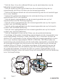
Plaats de module met de rugzijde tegen de achterzijde van de inbouwdoos,
achter de bedradingen.
• Indien de module nog niet of foutief geprogrammeerd is, kan deze nu
geprogrammeerd worden.
" Zie hoofdstuk programmeren.
Figuur 4.
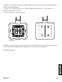
• Plaats na het programmeren de pulsdrukschakelaar terug in de inbouwdoos
en klik de drukknop met afdekraam terug op de pulsdrukschakelaar.
MONTAGE OP EEN 2 VLAKS PULSDRUKSCHAKELAAR - OMHOOG/
OMLAAG, PRESET EN LOCK
LET OP: Per SWM1P mag maar 1 motor tegelijk aangesloten worden.
Sluit nooit twee of meer motoren parallel aan!
Aangesloten op een dubbele 2 vlaks pulsdrukschakelaar kan naast de omhoog
en omlaag bediening van de zonwering ook met één toets naar de Preset
stand worden bewogen. Met de Lock toets kan de zonwering voor bediening
geblokkeerd worden, bijvoorbeeld in geval van onderhoudswerkzaamheden.
32
© MARMITEK
LET OP: Eerst de spanning uitschakelen voordat u met de montage begint.
Blauw (N)
Bruin
(L)
Zwart
P
Blauw
(N)
Geel/
Groen
Zwart
Figuur 5.
Neem de eventueel aanwezige pulsdrukschakelaar uit de inbouwdoos.
* Maak de bedrading los van de pulsdrukschakelaar.
* Trek een nuldraad (N) erbij indien deze ontbreekt.
PROG.
Figuur 6.
SWM1P
Paars
Grijs
Roze
N
DN
UP
L
Zwart
Bruin (L)
Blauw (N)
Wit
Motoraansluiting
P
Blauw (N)
Geel/Groen
Bruin (L)
SWM1P™
33
* Sluit de fase- (L) en de nuldraad (N) aan op de aansluitpunten van de
Marmitek zonweringmodule.
* Sluit de zwarte en de bruine draad van de motoraansluiting aan op
respectievelijk de DN en UP klem van de zonweringmodule.
* Verbind de blauwe draad van de motoraansluiting met de nul aansluitingen
d.m.v. een steeklas.
* Verbind de geel/groene draad van de motoraansluiting met de aarde
aansluitingen d.m.v. een steeklas.
* Sluit de paarse ingangsdraad van de zonweringmodule aan op het
impulscontact voor de Omhoog regeling.
* Sluit de witte ingangsdraad van de zonweringmodule aan op het impulscontact voor de Omlaag regeling.
* Sluit de grijze ingangsdraad van de zonweringmodule aan op het impulscontact voor de Preset bediening.
* Sluit de roze ingangsdraad van de zonweringmodule aan op het impulscontact voor de Lock bediening.
* Sluit de fasedraad (L) aan op de P-klem van de pulsdrukschakelaar.
* Controleer of de motor looprichting overeenkomt met de commando’s voor
Omhoog/Omlaag (Omhoog = AAN, Omlaag = UIT) Controleer dit door de
AAN en UIT commando’s via het lichtnet naar de zonweringmodule te sturen
d.m.v. een interface (bijvoorbeeld: PRU512, PRU256, CM15Pro).Indien de
looprichting niet overeenkomt met de verstuurde commando’s, verwissel dan
de motoraansluitingen van de bruine en de zwarte draad op de zonweringmodule (DN en UP klem). Controleer vervolgens of de looprichting van de
motor overeenkomt met de bediening van de Omhoog/Omlaag toets van
de pulsdrukschakelaar. Verwissel de witte en paarse ingangsdraden op de
pulsdrukschakelaar indien de looprichting niet overeenkomt met de bediening
voor Omhoog/Omlaag.
PROG.
SWM1P
P
N
DN
UP
L
Figuur 7.
34
© MARMITEK
* Plaats de module met de rugzijde tegen de achterzijde van de inbouwdoos,
achter de bedradingen.
* Indien de module nog niet of foutief geprogrammeerd is, kan deze nu
geprogrammeerd worden.
" Zie hoofdstuk programmeren.
Figuur 8.
* Plaats na het programmeren de pulsdrukschakelaar terug in de inbouwdoos
en klik de drukknoppen met afdekraam terug op de schakelaar.
Installatie gereed.
SWM1P™
35
PROGRAMMEREN
LET OP: Eerst de spanning inschakelen voordat u gaat programmeren.
Vermijdt het aanraken van stroomvoerende delen!
In de programmeer mode kunnen de adressen van de ingangen 1 en 2 (motor
adres) en van ingang 4 (Preset adres) onafhankelijk van elkaar worden geprogrammeerd. Ook moeten de eindstanden van de motor worden geprogrammeerd om
deze overeen te laten komen met de positie waarden van 0% en 100%.
Programmering
Voor het programmeren van de module moeten onderstaande 5 stappen
worden doorlopen.
1. Zet de module in de programmeermode.
2. Verstuur het motor adres.
3. Programmeer de motor eindstanden.
4. Programmeer het Preset adres (optioneel).
5. Verlaat de programmeermode.
Deze stappen worden nader toegelicht.
1. Zet in programmeermode
Om de zonweringmodule te kunnen programmeren, moet deze als volgt in de
programmeermode worden gebracht:
* Druk het programmeerknopje minimaal drie seconden in, zie figuur 9,
waarna de rode LED bij het loslaten gaat branden.
* Gebruik de automatische programmeerfunctie van de PRU512.
Zie hiervoor de gebruiksaanwijzing van de PRU512
P
PROG.
SWM1P
N
DN
UP
L
PROG.
Figuur 9. Activeren en opheffen van de programmeermode.
36
© MARMITEK
2. Verstuur het motoradres
Verzend het set-up commando (lettercode en cijfercode, ON of OFF) dat bij
het gewenste adres hoort twee keer via het lichtnet met bijv. een programmeerunit (PRU256, PRU512), of een andere X-10-compatibele zender (bijvoorbeeld een Marmitek EasyControl8 afstandsbediening). De LED knippert één
keer nadat twee identieke set-up commando’s (adressen) ontvangen zijn.
Standaard
Optioneel
Setup commando
Aantal LED knipperingen
Adres A1
A1..P16
Nieuw adres
1
LET OP:
* In programmeermode altijd eerst het adres instellen, voer daarna de
overige instellingen in.
* Als er, direct na het in de programmeerstand brengen van de module, 2 x een adres wordt verstuurd zal het Preset adres van de module
het daaropvolgend adres aannemen.
3. Programmeer de motoreindstanden
Sla deze stap over indien de SWM1P al eerder op de eindstanden
geprogrammeerd is en de eindstanden van de motor ongewijzigd
moeten blijven. Ga in dat geval door naar stap 4.
Als de SWM1P voor de eerste keer geprogrammeerd wordt dienen de eindstanden te worden ingesteld. Hiervoor dienen de volgende stappen doorlopen
te worden:
LET OP: De motor moet in de bovenste positie staan (helemaal
omhoog, 100%) voordat aan de onderstaande stap begonnen kan
worden. Beweeg de motor geheel omhoog met de omhoog toets
mocht dit nog niet het geval zijn.
Beweeg de motor omlaag door de omlaag toets in te drukken en vast te houden totdat de motor de onderste positie
(0%) heeft bereikt en tel hier ongeveer 1 seconde bij op. Laat
vervolgens de omlaag toets los. De benodigde tijd voor deze
beweging inclusief de extra tijd wordt nu opgeslagen.
SWM1P™
37
Beweeg de motor nu omhoog door de omhoog toets
in te drukken en vast te houden totdat de motor
de bovenste positie (100%) heeft bereikt en tel hier
ongeveer 1 seconde bij op. Laat vervolgens de omhoog
toets los. De benodigde tijd voor deze beweging inclusief de extra tijd wordt nu opgeslagen.
Bovenstaande stappen mogen meerdere keren achtereen herhaald
worden. Elke nieuwe beweging zal worden opgeslagen. Mocht u de
knop te vroeg los laten dan dient u de motor eerst weer helemaal
omhoog of omlaag te brengen en hierboven genoemde stappen in
willekeurige volgorde te herhalen.
4. Programmeer het Preset adres
Indien het Preset adres op een ander adres moet worden geprogrammeerd
dan het standaard adres (dit is het eerst opvolgende adres van het motor)
dan dient de het set-up commando van het gewenste adres twee maal via
het lichtnet verzonden te worden met bijv. een programmeerunit (PRU256 of
PRU512), of een andere X-10- compatibele zender (bijvoorbeeld een Marmitek
EasyControl8 afstandsbediening).
Standaard
Optioneel
Setup commando
Aantal LED
knipperingen
Preset adres A2
A1..P16
Nieuw adres
2
Het bepalen van de Preset stand staat omschreven in het hoofdstuk
“Bedieningsinstructies”.
5. Verlaat programmeermode
* Druk éénmaal kort op het programmeerknopje; de rode LED is nu uit, of
wacht 60 seconden waardoor de programmeermode automatisch wordt
opgeheven.
LET OP: Indien binnen 60 sec. geen instelcommando ontvangen wordt,
gaat de module automatisch weer uit de programmeermode.
38
© MARMITEK
BEDIENINGSINSTRUCTIES
Zie onderstaand tabel voor de betekenis van de symbolen met bijbehorende
ingangen.
Symbool
Bediening
Met deze toets beweegt de zonwering Omhoog.
Met deze toets beweegt de zonwering Omlaag.
Met deze toets beweegt de zonwering naar de
geprogrammeerde Preset stand.
Met deze toets (In combinatie met andere toetsen) kan de werking van de zonweringmodule worden in- en uitgeschakeld.
Onderstaande tabel geeft de relaties weer tussen de verschillende motorbewegingen en commando’s met de stand van het rolluik of de zonwering.
Symbool
Module
Beweging
aansluitklem
Positie
Commando’s Positie
Rolluik
positie
Zonwering
UP
Omhoog
100%
X%
Aan (On)
dim+
(BRIGHT)
Open
In
DN
Omlaag
0%
X%
Uit (Off)
Dim - (DIM)
Gesloten
Uit
Opmerking: De Omhoog en Omlaag commando’s van de zonweringmodule
corresponderen respectievelijk met de DIM+ en DIM- commando’s van een
dimmer module.
SWM1P™
39
Handmatige bediening
Omhoog/omlaag
Met de Omhoog en Omlaag toets van de pulsdrukschakelaar kan de zonwering in de gewenste positie gebracht worden door middel van korte en lange
pulsen.
Omhoog functie
Kort drukken: De zonwering (rolluik) beweegt naar binnen
(omhoog), naar de uiterste stand.
Lang drukken: De zonwering (rolluik) beweegt naar binnen
(omhoog) totdat de toets wordt losgelaten. De beweging stopt
dan direct.
Omlaag functie
Kort drukken: De zonwering (rolluik) beweegt naar buiten
(omlaag), naar de uiterste stand.
Lang drukken: De zonwering (rolluik) beweegt naar buiten
(omlaag) totdat de toets wordt losgelaten. De beweging stopt
dan direct.
Zodra de toets wordt losgelaten verstuurt de zonweringmodule een
Marmitek X-10 EXTENDED commando over het lichtnet met zijn nieuwe
stand, eventueel met een AAN of UIT commando indien de zonwering
respectievelijk in de 0% positie komt danwel in de 100% positie komt.
Preset functie
Met de Preset functie kan een gewenste voorkeurstand van de
zonwering of rolluik worden vastgelegd en achteraf met een
simpele druk op de knop worden opgeroepen.
Vastleggen van de Preset stand
Zodra de zonwering of het rolluik de gewenste positie heeft bereikt (te bedienen met de UP en DN toets) kan deze positie worden vastgelegd door de
Preset toets langer dan 5 seconden ingedrukt te houden. De huidige positie
zal als Preset worden opgeslagen. De module beschikt over 25 mogelijke
Preset waarden. Indien de gewenste positie van deze mogelijke waarden
afwijkt, zal de module deze positie afronden naar de dichtstbijzijnde mogelijke
waarde. Deze waarde kan maximaal 4 % afwijken van de gekozen positie.
40
© MARMITEK
Bedienen van de Preset functie
Door de Preset toets in te drukken beweegt de zonwering naar de vastgelegde
Preset stand. De zonweringmodule verstuurt een EXTENDED commando over
het lichtnet met zijn nieuwe stand. De zonweringmodule verstuurt ook een
AAN commando op zijn Preset adres. Hiermee kunnen eventuele andere
zonweringen of rolluiken naar hun eigen Preset stand gaan. Indien de zonwering vanuit een Preset positie komt, zal de zonweringmodule ook een UIT
commando op het Preset adres versturen.
De zonweringmodule zal niet reageren als de zonwering zich al op de Preset
positie bevindt.
Lock functie
Tijdens bijvoorbeeld werkzaamheden aan het zonnescherm of
schilderwerkzaamheden bij het zonnescherm kan met de Lock
toets de bediening van de zonweringmodule tijdelijk worden
geblokkeerd.
LET OP: Schakel de spanning bij werkzaamheden aan de motor of de
zonweringmodule altijd af!
LET OP: Indien de module vanuit de Lock functie in de programmeermode wordt gezet zal de Lock functie na het programmeren automatisch worden opgeheven.
Zonweringmodule blokkeren
Druk de Lock toets tegelijkertijd met de Omlaag toets langer dan 5 seconden
in. De zonweringsactor is geheel geblokkeerd voor alle bediening (handbediening en via het lichtnet). De motor stopt direct zodra de Lock toets wordt
ingedrukt. Indien de Lock toets korter dan 5 seconden wordt ingedrukt zal de
motor na het loslaten van de Lock toets weer doorlopen.
LET OP: Controleer middels lokale bediening en bediening op afstand
of de zonweringmodule geblokkeerd is alvorens met de werkzaamheden te starten!
LET OP: Neem geen enkel risico en schakel de spanning af, indien er
zich meerdere personen in de woning bevinden!
SWM1P™
41
Zonweringmodule inschakelen
Druk de Lock toets tegelijkertijd met de Omhoog toets langer dan 5 seconden
in. De zonweringmodule werkt weer normaal.
LET OP: Controleer of het zonnescherm vrij kan bewegen alvorens de
blokkering op te heffen!
Bediening op afstand
Onderstaande tabel geeft de verschillende mogelijke besturingscommando’s
weer voor het bedienen van de zonweringmodule.
Commando
Reactie
<Motor adres> Aan
De zonwering beweegt geheel Omhoog.
<Motor adres> Uit
De zonwering beweegt geheel Omlaag.
<Motor adres> DIM+
De zonwering beweegt één stap Omhoog. Bij meerdere DIM+ commando’s achter elkaar zal de zonwering blijven bewegen totdat de Commando’s stoppen
of de zonwering in de eindpositie geraakt.
<Motor adres> DIM-
De zonwering beweegt één stap Omlaag. Bij meerdere
DIM- commando’s achter elkaar zal de zonwering
blijven bewegen totdat de Commando’s stoppen of de
zonwering in de eindpositie geraakt.
<Motor adres> Extended
De zonwering beweegt naar de positie aangegeven in
het extended commando.
<Preset adres> Aan
De zonwering beweegt naar zijn opgeslagen Preset stand.
<Preset adres> Uit
Geen.
<Preset adres> Extended
De waarde in het extended commando wordt als
Preset stand in de zonweringmodule opgeslagen. De
zonwering beweegt niet.
Hieronder zijn een aantal praktische programmeer voorbeelden gegeven.
Meerdere rolluiken met één Preset stand
Programmeer het Preset adres van alle zonweringen in bijvoorbeeld de
woonkamer op hetzelfde adres. Met de Preset toets van willekeurige zonweringmodulen in deze ruimte of door middel van het versturen van het Preset
42
© MARMITEK
adres AAN via een Marmitek interface kunnen alle zonweringen gelijktijdig op
de Preset stand worden gezet.
Meerdere Presets voor één zonwering
Als men in de morgen behoefte heeft aan een andere Preset stand dan in de
middag, kan men middels scenario’s die in de Marmitek CM15Pro Computer
Interface kunnen worden geprogrammeerd deze positie op het Preset adres
middels extended commando van te voren programmeren. Bij het bedienen
van de Preset toets zal de zonwering zich bewegen naar de op dat moment
geprogrammeerde positie.
Spanningsuitval
Indien tijdens de beweging van de motor de spanning uitvalt, zal de motor op
zijn positie blijven staan bij het opnieuw op spanning komen van de zonweringmodule. Bij de eerst volgende bediening naar een tussenliggende positie
zal de motor eerst een calibratieslag naar boven of beneden maken alvorens
naar de gewenste positie te gaan.
LET OP: Zowel de motor als de SWM1P worden door een thermische
beveiliging beschermd tegen oververhitting. Een zonwering- of rolluikmotor mag nooit langer dan 4 minuten achtereen draaien. Indien de
motor onverhoopt toch langer dan 4 minuten draait zal de beveiliging
van de motor of de SWM1P inschakelen en zal de motor stoppen.
De motor is pas weer te bedienen zodra de motor cq. de module
voldoende afgekoeld zijn. Dit kan enkele minuten duren!
Troubleshooting
Volg onderstaande checklist in geval van problemen.
Constatering: De zonwering werkt niet.
Checklist:
1. Controleer in de meterkast of alle spanning aanwezig is. Zo
ja, ga naar de volgende stap.
2. Druk de Lock toets en de Omhoog toets tegelijkertijd in voor
meer dan 5 seconden. Ga naar de volgende stap als dit het
probleem niet oplost.
3. Controleer of het ledje op de zonweringmodule knippert.
4. Controleer de zekering.
Constatering: De zonwering regeert niet op de Preset toets.
Checklist:
1. De zonwering staat al in de Preset stand of de toets is langer
dan 5 seconden ingedrukt.
2. Controleer of de Lock functie actief is
SWM1P™
43
TESTEN EN VERVANGEN VAN DE ZEKERING
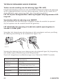
Testen van de werking van de zekering (type TR5 -4AT)
Koppel de belasting (motor) los van de SWM1P. Meet vervolgens de spanning
op de uitgangsklemmen met een spanningsmeter. Indien er op zowel de UP
als de DN klem geen spanning staat, dan is de zekering defect.
LET OP: Bij een doorgesmolten zekering knippert de programmeer LED
nog wel.
Verwisselen defecte zekering voor SWM1P
Het verwisselen van de zekering is mogelijk zonder de module te openen!
(bij het openen van de module vervalt de garantie).
LET OP:Schakel de spanning uit zodat de module spanningsloos is
voordat u verder gaat.
Verwijder het vliesje boven de zekering en trek vervolgens met een punttang
de zekering voorzichtig uit de module (zie figuur 10).
2
PROG.
PROG.
SWM1P
N
DN
UP
SWM1P
L
N
DN
UP
L
3,3 mm
Figuur 10.
Vervang de zekering door een zekering van de volgende types (bij toepassing
van andere types dimzekering vervalt de garantie):
Overzicht toegestane modulezekeringen voor Marmitek SWM1P module.
Leverancier zekering
Omschrijving
Littelfuse
LT-5 ALg
Bussman
ETF Radial Lead Micro Fuse
ELU
Subminiature fuse links
Wickmann
Subminiatur fuse No 372.TR5
Bel fuse
Time Lag Radial Lead Micro Fuse
44
© MARMITEK
VEEL GESTELDE VRAGEN
Hoe komt het dat sommige Modules spontaan aan- of uitgaan?
Het kan zijn dat het geïnstalleerde Marmitek X-10 Systeem beïnvloed wordt
door een ander X-10 Systeem in de buurt. Aangezien de Marmitek X-10
signalen over het lichtnet worden verstuurd is het mogelijk dat de signalen
het pand inkomen of verlaten. Dit probleem kan verholpen worden door het
kiezen van een andere HuisCode (A .. P). Ook kunnen FD10 Fase Koppelfilters
geplaatst worden om in- en uitgaande signalen te blokkeren.
Mijn modules reageren niet op mijn controller.
Zorg ervoor dat alle gebruikte componenten ingesteld zijn op de zelfde
Huiscode (lettercode A..P).
Mijn modules reageren niet op mijn afstandsbediening of sensor.
Bij het gebruik van afstandsbedieningen of sensoren dient u gebruik te
maken van een TM13 Transceivermodule of een centrale van een Marmitek
X-10 Alarmsysteem. Deze zetten de signalen van de afstandsbedieningen
en sensoren om naar het Marmitek X-10 lichtnetprotocol. Ook bij meerdere
afstandsbedieningen en sensoren is maar één centrale transceiver nodig.
Kan ik het bereik van mijn afstandsbediening vergroten door de inzet
van meer Transceivers?
Ja. U kunt meerdere TM13 Transceivers in uw woning gebruiken als het bereik
van uw afstandsbedieningen niet toereikend is. De TM13’s zijn voorzien van
zgn. collision detection om te voorkomen dat de signalen verstoord worden
wanneer beide TM13 units gelijktijdig gaan zenden op het lichtnet. Om uw
Marmitek X-10 niet onnodig traag te maken en om het horten en stoten
bij dimmen te voorkomen moet u er voor zorgen dat de TM13 units zo ver
mogelijk van elkaar in de woning worden geplaatst.
Heeft u vragen die hierboven niet beantwoord worden? Kijk dan op
www.marmitek.com.
TECHNISCHE GEGEVENS
Voedingsspanning:
Schakelvermogen:
Beveiliging:
SWM1P™
230 VAC+/- 10%, 50 Hz
500W/230 VAC met temperatuur en
bevestigingrestricties.
Continu aanstuurtijd maximaal 4 minuten.
Temperatuursbeveiliging uitgang.
45
Verbruik:
Zekering:
Stroomverbruik:
Signaal transmissie:
X-10 transmissie:
Signaal gevoeligheid:
Signaal/ruis verhouding:
X-10 Key codes zenden:
X-10 Key codes ontvangen:
Aansluitbereik:
Omgevingstemperatuur:
Relatieve luchtvochtigheid
(non condensing):
Afmetingen:
<1W
Radial lead micro fuse, 4 AT.
< 30 mA capacitief
> 5 Vpp in 5 7 bij 120 kHz
1 puls op 0° en 180°
25 mVpp...6 Vpp bij 120 kHz ± 4 kHz
1,35 : 1
ON, OFF, extended
ON, OFF, DIM+, DIM-, extended, Status Request
Tot 2,5 mm2, aandraaimoment 0,5 Nm
0 °C tot 40 °C
30 tot 90%
46x46x16mm.
Milieu-informatie voor klanten in de Europese Unie
De Europese Richtlijn 2002/96/EC schrijft voor dat apparatuur die is
voorzien van dit symbool op het product of de verpakking, niet mag
worden ingezameld met niet-gescheiden huishoudelijk afval. Dit
symbool geeft aan dat het product apart moet worden ingezameld. U bent
zelf verantwoordelijk voor de vernietiging van deze en andere elektrische en
elektronische apparatuur via de daarvoor door de landelijke of plaatselijke
overheid aangewezen inzamelingskanalen. De juiste vernietiging en recycling
van deze apparatuur voorkomt mogelijke negatieve gevolgen voor het milieu
en de gezondheid. Voor meer informatie over het vernietigen van uw oude
apparatuur neemt u contact op met de plaatselijke autoriteiten of afvalverwerkingsdienst, of met de winkel waar u het product hebt aangeschaft.
Copyrights
Marmitek is a trademark of Marmidenko B.V. SWM1PTM is a trademark of Marmitek B.V. All
rights reserved.
Copyright and all other proprietary rights in the content (including but not limited to model
numbers, software, audio, video, text and photographs) rests with Marmitek B.V. Any use
of the Content, but without limitation, distribution, reproduction, modification, display or
transmission without the prior written consent of Marmitek is strictly prohibited. All copyright
and other proprietary notices shall be retained on all reproductions.
46
© MARMITEK
DECLARATION OF CONFORMITY
Hereby, Marmitek BV, declares that this SWM1P is in compliance with the essential
requirements and other relevant provisions of the following Directives:
DIRECTIVE 2004/108/EC OF THE EUROPEAN PARLIAMENT AND OF THE COUNCIL of 15 December
2004 on the approximation of the laws of the Member States relating to electromagnetic
compatibility
Directive 2006/95/EC of the European Parliament and of the Council of 12 December 2006 on
the harmonisation of the laws of Member States relating to electrical equipment designed for use
within certain voltage limits
Directive 2002/95/EC of the European Parliament and of the Council of 27 January 2003 on the
restriction of the use of certain hazardous substances in electrical and electronic equipment
Bij deze verklaart Marmitek BV, dat deze SWM1P voldoet aan de essentiële eisen en aan
de overige relevante bepalingen van Richtlijnen:
RICHTLIJN 2004/108/EG VAN HET EUROPEES PARLEMENT EN DE RAAD van 15 december 2004
betreffende de onderlinge aanpassing van de wetgevingen van de lidstaten inzake
elektromagnetische compatibiliteit
Richtlijn 2006/95/EG van het Europees Parlement en de Raad van 12 december 2006 betreffende
de onderlinge aanpassing van de wettelijke voorschriften der lidstaten inzake elektrisch materiaal
bestemd voor gebruik binnen bepaalde spanningsgrenzen
Richtlijn 2002/95/EG van het Europees Parlement en de Raad van 27 januari 2003 betreffende
beperking van het gebruik van bepaalde gevaarlijke stoffen in elektrische en elektronische
apparatuur
MARMITEK BV - P.O. BOX 4257 - 5604 EG EINDHOVEN – NETHERLANDS
SWM1P™
47