1
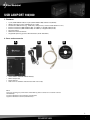
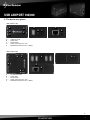
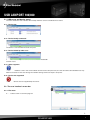
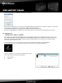
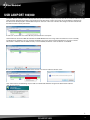
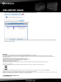
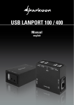
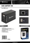
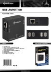
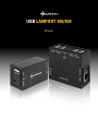
USB LANPORT 100/400 Manual USB LANPORT 100/400 Content page 1. Features 1 2. Parts and accessories 1 3. The device at a glance 2 4. Getting started 4.1 Hardware installation 4.2 Software installation (Windows for example) 3 3 3 5. The user interface 5.1 USB server and device status 5.1.1 Device free 5.1.2 Device locally connected 5.1.3 Device locked by other user 5.1.4 Other segment 5.1.5 Device not supported 3 4 4 4 4 4 4 5.2 The user interface’s menu bar 5.2.1 File menu 5.2.2 Options menu 5.2.3 View menu 5.2.4 Help menu 4 4 5 5 5 5.3 USB server context menu 5.3.1 Backup firmware 5.3.2 Firmware update 5.3.3 Change password 5.3.4 Restart server 6 6 6 6 6 7 5.4 Device context menu 6. Configuration via web interface 6.1 Status 6.2 Network 6.3 Reset Device 6.4 Password Change 7 7 8 8 8 7. Disconnect request 8 8. Important notes 9 9. Examples of use 9.1 Network use (single user, IP address manually assigned) 9.2 Network use (multiple users, IP address by DHCP) Dear customer! Congratulations for purchasing this premium quality SHARKOON product. For a long life time and to take full advantage of this product we recommend you to read this manual completely. Enjoy our product! SHARKOON Technologies 10 10 11 USB LANPORT 100/400 1. Features • • • • • • • • 1-port (USB LANPort 100) or 4-port (USB LANPort 400) USB server (NDAS) Allows connecting many USB devices to a LAN Suitable for USB devices (e.g. USB sticks, USB printers, external hard disk drives etc.) External interfaces (USB LANPort 100): 1x USB2.0, 1x Gigabit LAN (RJ-45) External interfaces (USB LANPort 400): 4x USB2.0, 1x Gigabit LAN (RJ-45) Compact design Power LED and reset button Supported operating systems: Win XP/Vista/7 (32-bit and 64-bit) 2. Parts and accessories A • • • • B C D USB LANPort 100/USB LANPort 400 (A) Power adapter (B) Patch cable (C) Tools CD incl. software and extensive PDF manual (D) Note: If you are missing any of the items listed above, please contact our customer service immediately: [email protected] (Germany and Europe) [email protected] (international). 1 USB LANPORT 100/400 3. The device at a glance USB LANPort 100: A D B E A B E C D C A– B– C– D– E – USB connector Power LED Reset button Power connector (5 V / DC) Network connector (RJ-45 / 1 GBit/s) USB LANPort 400: D E A A B C E D B C A– B– C– D– E – 4x USB connector Power LED Reset button Power connector (5 V / DC) Network connector (RJ-45 / 1 GBit/s) 2 USB LANPORT 100/400 4.Getting started 4.1 Hardware installation 1. Connect the included patch cable to the USB LANPort’s network connector and an available network connector of your switch/hub/router/PC or similar. 2. Connect the included power adapter to the USB LANPort and a wall outlet. The device will boot automatically. 4.2 Software installation (Windows for example) 1. Insert the included Tools CD into your CD/DVD drive. 2. Use the Windows Explorer to open the directory of the inserted Tools CD. 3. Double click (left mouse button) “Setup.exe”. The installation procedure will start. Follow the installation wizard’s instructions. 4. To complete the installation you will be prompted to reboot your PC. Confirm this indication. 5. After successfully rebooting your system, the following icon will appear on your desktop: Double-click (left mouse button) this icon to launch the software. Note: You need to install this server software on every PC from which you want to access the USB LANPort. 5. The user interface A – Menu bar showing the entries “File“, “Options“, “View“ and “Help“ B – USB server with related IP address C – USB devices connected to the USB server D – “Search” button: by left-clicking a search run is commenced, to detect devices connected to the USB server E – “Open Web Page” button (only displayed when the USB Server is selected): by left-clicking the USB server’s web interface will be opened F – “Connect device” button (only displayed when a plugged USB device is selected): by left-clicking this button the respective USB device is connected and locked for other users A B C D E F Note: The software will detect the connected USB server and associated devices automatically. Furthermore the USB server supports automatic and manual IP address assignment; automatic address assignment via DHCP is selected by default. In case your firewall prompts you during the installation process allow the USB server to access the respective network resources. 3 USB LANPORT 100/400 5.1 USB server and device status The icons inside the user interface will already show the server’s and the device’s status. 5.1.1 Device free The device is not locked and can be connected. 5.1.2 Device locally connected The device is connected to the local computer. 5.1.3 Device locked by other user The device is locked by another user and therefore is blocked for all other users. 5.1.4 Other segment The server IP address is not in the same network context as the computer’s IP; thus the server/the connected devices may NOT be accessed. In this case change the network settings of the server/your computer. 5.1.5 Device not supported Some USB devices are not supported by the server. 5.2 The user interface’s menu bar 5.2.1 File menu A A – Choose “Quit” to exit the program. 4 USB LANPORT 100/400 5.2.2 Options menu A – Select the desired interface language. B – Decides (box checked/unchecked) if the selected device shall be automatically connected when starting the server software. C – Accesses the server configuration menu (below 5.3). D – Retrieves the web interface for server configuration (below 6.). E – In case a device is selected, it is mounted and locked for other users (same function as the “Connect device” button). F – Disconnects a mounted device and unlocks it for other users (same function as the “Disconnect device” button). G – Sends a disconnect request (below 7.) to the current user of a mounted device. H – Opens up the active device‘s configuration dialogue (below 5.4). I – Decides (box checked/unchecked), if an inactive memory device (e.g. HDD in sleep mode) will automatically be unmounted from the server. J – Selects (box checked/unchecked), if an inactive printer will automatically be unmounted from the server. A C E G I B D F H J 5.2.3 View menu A – Decides (box checked/unchecked) if only connected devices or also the server will be displayed. A 5.2.4 Help menu A – Displays some software information: B – Defines (box checked/unchecked) if a log file will be kept. C – Opens up the program folder where the log file is kept: A C B 5 USB LANPORT 100/400 5.3 USB server context menu A – Invokes the server’s configuration window: A B a b c d e a – Define the USB server’s name b – DHCP on (manual IP address off) / DHCP off (manual IP address on) c – Decide which USB port(s) shall automatically be mounted at program start d – “Set“ saves and activates your settings “Cancel“ discards them e – The entries “Backup Firmware“, “Firmware update“, “Change password“ and “Server restart“ (see below) B – Calls up the web interface (below 6.) 5.3.1 Backup firmware The USB server offers the possibility to backup the firmware. The pop-up window already offers a target path for the backup file. Via “Browse” you can change this default path. “Submit” starts the backup, “Cancel” will terminate the action. In this input window you may assign a new password. This password is required to configure different settings of the USB server. 5.3.2 Firmware update In case you have a more actual version of the USB server’s firmware available you may update the current firmware version via this entry. With “Browse” you select the locally saved update version. “Submit” starts, “Cancel” terminates the update procedure. A current firmware version can be found at www.sharkoon.com. 5.3.3 Change password In this input window you may assign a new password. This password is required to configure different settings of the USB server. 5.3.4 Restart server Select this entry to restart the USB server. A restart may be necessary when the server does not react or other problems have occurred. You may also force a restart by pressing the reset button on the device. 6 USB LANPORT 100/400 5.4 Device context menu A – The selected device is mounted and locked for other users (same function as the “Connect device” button). B – Opens up the device’s settings window: A B C a b a – Various device information is displayed. b – Select a program to be run after the respective device has been mounted. C – Decides (box checked/unchecked) if the device is mounted automatically at program start. 6. Configuration via web interface From the user interface select the server entry and click the button “Open Web Page” afterwards: Your standard browser starts and the web interface will display the status page: 6.1 Status A– B– C– Left-click the link to select the respective entry. This area displays various USB server information: Server Name, Manufacturer, Model, Firmware Version and Server Up-Time (time elapsed since server has been started). These areas display various information regarding the connected devices: Device Name, Link Status, Device Status and Current User. A B C 7 USB LANPORT 100/400 6.2Network A– B– Left-click the link to select the respective entry. This area displays the current network status: IP Setting (automatic or manual IP address assignment), IP Address (IP address assigned to the server), Subnet Mask, MAC Address (the server’s MAC address). A B 6.3 Reset Device A– B– Left-click the link to select the respective entry. Perform a reset after entering the assigned password into the “Password” area and confirm by clicking the “Submit” button, “Clear” will discard your entry. A B 6.4 Password Change A – Left-click the link to select the respective entry. B – To change the current password enter it into the “Current Password” area, then enter the newly assigned password into the “New Password” area. Confirm the new pass word by re-typing it into the “Confirm New Password” area. Left-clicking “Submit” will complete this procedure, “Clear” will abort. A B C 7. Disconnect request A device being connected to the USB server and mounted by a single user is contemporaneously locked for all other users. The icon “Remote Occupied” indicates that the connected device currently is not available; the button “Connect Device” is disabled. Now via the device’s context menu a disconnect request can be sent to the current user: 8 USB LANPORT 100/400 The current user decides whether he unlocks the device “OK” or not “Cancel”: As soon as the device is unlocked the requester will receive the following info and now can mount the device by clicking the “Connect device” button. 8. Important notes 1. You need to install the server software on every PC, from which you want to access the USB LANPort. 2. Your operating system will treat the connected USB device as if it is directly connected to the PC. This means that potential drivers (e.g. printer drivers) need to be installed on the system (for further details refer to the manuals of the according devices). 3. As the devices will be handled like directly attached hardware, we suggest to remove memory devices (HDDs, USB sticks etc.) using the “Safely remove hardware” function before terminating the connection via “Disconnect”. The server software will also prompt you with the following note: Other USB devices such as printers, scanners etc. do not require this step and can directly be disconnected. 4. The USB to IP translation may cause a decrease in transfer speed compared to the native operation of the USB devices and is caused by technical means. 9 USB LANPORT 100/400 9. Examples of use 9.1 Network use (single user, IP address manually assigned) User A wants to integrate the USB LANPort into his local network and connects the docking station to his router using the included patch cable. He plugs a SATA HDD and a USB stick to the USB LANPort; his IP addresses were configured manually; a DHCP server is not activated. Router: 192.168.10.1 Computer: 192.168.10.2 User A installed the included software on his computer and starts it by double-clicking (left mouse button) on the desktop icon: The server software’s user interface will display the USB server: The software has detected the USB server and assigned it a standard IP address, but this address is from another address range (error message: “in different network segment”). The device may not be accessed yet; first the server must be assigned an IP address from the local network’s address range. Right-clicking the USB server’s entry inside the user interface brings up the server’s context menu: 10 USB LANPORT 100/400 “Server Configurations” invokes the following input window: User A unchecks “Use DHCP” (this function is activated by default), afterwards the input fields “IP address” and “Subnet” can be filled in. The USB server is assigned the IP address 192.168.10.101 in the subnet 255.255.255.0. To save the settings User A needs to left-click the button “Set”. After that the USB LANPort is available in the local network and user A may access the connected memory devices. 9.2 Network use (multiple users, address by DHCP) User A wants to integrate the USB LANPort into his local network and connects the docking station to his router using the included patch cable. He plugs a SATA HDD to the USB LANPort; IP addresses are assigned by a DHCP server. User A already has installed the server software delivered with the USB LANPort on all his computers in the local network (living room, office, children’s room). From his office computer user A now wants to access the hard disk drive plugged into the USB LANPort: to this he commences the server software by double clicking (left mouse button) the desktop icon. The server software’s user interface will then display the USB server and all devices currently connected to it: A – External HDD B – USB stick A B 11 USB LANPORT 100/400 The blue “device available” icon indicates that the respective device may be mounted. For this A selects the device (1x left click) and then left-clicks the button “connect device”.The operating system will install all required drivers whereupon the device will be displayed in the Windows Explorer. The icon in the user interface will change and now indicate that the HDD has been locally connected: A now can use the HDD as if it was directly connected to his computer. User B wants to access the HDD connected to the USB LANPort from the living room. Therefore he runs the already installed server software. The user interface will display the server with all connected devices: the icon “remote connection” indicates that the HDD currently is not available; the button “connect device” is disabled. B now can send a disconnect request to the current user A via the device context menu: User A will receive the following request and can now decide whether he agrees to disconnect the device “OK” or not “Cancel”: 12 USB LANPORT 100/400 As soon as A has disconnected the device, B will receive the following info and now can access the device via “Connect” by himself. When B does no longer need the device he can dismount it by clicking the “Disconnect button” and thereby unlock the device for further usage. Warning: For potential loss of data, especially due to inappropriate handling, SHARKOON assumes no liability. All named products and descriptions are trademarks and/or registered trademarks of the respective manufacturers and are accepted as protected. As a continuing policy of product improvement at SHARKOON, the design and specifications are subject to change without prior notice. National product specifications may vary. The legal rights of the enclosed software belong to the respective owner. Please observe the license terms of the manufacturer before using the software. All rights reserved especially (also in extracts) for translation, reprinting, reproduction by copying or other technical means. Infringements will lead to compensation. All rights reserved especially in case of assignation of patent or utility patent. Means of delivery and technical modifications reserved. Disposal of your old product Your product is designed and manufactured with high quality materials and components, which can be recycled and reused. When this crossed-out wheeled bin symbol is attached to a product, it means the product is covered by the European Directive 2002/96/EC. Please be informed about the local separate collection system for electrical and electronic products. Please act according to your local rules and do not dispose of your old products with your normal household waste. The correct disposal of your old product will help prevent potential negative consequences to the environment and human health. © SHARKOON Technologies 2011 www.sharkoon.com 13