1
Simple
version
v
Versión sencilla
3
Basic
version
v
Version simplifiée
Version basique
Versión básica
12
AV SURROUND RECEIVER
AVR-2311
Advanced
version
v
Version avancée
Versión avanzada
32
Owner’s Manual
Manuel de l’Utilisateur
Manual del usuario
Information
v
v
Book 1
English
Book 2
Deutsch Italiano
Français Español
Nederlands
Svenska
71
“Part names and functions”
(vpage 72)
Informations
“Nomenclature et fonctions“
(vpage 72)
Información
“Nombres y funciones de las
piezas“ (vpágina 72)
ENGLISH
DEUTSCH FRANCAIS ITALIANO ESPAÑOL NEDERLANDS SVENSKA
nSAFETY PRECAUTIONS
CAUTION
RISK OF ELECTRIC SHOCK
DO NOT OPEN
CAUTION:
TO REDUCE THE RISK OF ELECTRIC SHOCK, DO NOT REMOVE
COVER (OR BACK). NO USER-SERVICEABLE PARTS INSIDE.
REFER SERVICING TO QUALIFIED SERVICE PERSONNEL.
The lightning flash with arrowhead symbol, within an equilateral
triangle, is intended to alert the user to the presence of
uninsulated “dangerous voltage” within the product’s enclosure
that may be of sufficient magnitude to constitute a risk of
electric shock to persons.
The exclamation point within an equilateral triangle is intended
to alert the user to the presence of important operating
and maintenance (servicing) instructions in the literature
accompanying the appliance.
WARNING:
TO REDUCE THE RISK OF FIRE OR ELECTRIC SHOCK, DO NOT
EXPOSE THIS APPLIANCE TO RAIN OR MOISTURE.
1.
2.
3.
4.
5.
6.
7.
8.
9.
10.
11.
12.
IMPOTANT SAFETY
INSTRUCTIONS
Read these instructions.
Keep these instructions.
Heed all warnings.
Follow all instructions.
Do not use this apparatus near water.
Clean only with dry cloth.
Do not block any ventilation openings.
Install in accordance with the manufacturer’s instructions.
Do not install near any heat sources such as radiators, heat registers,
stoves, or other apparatus (including amplifiers) that produce heat.
Protect the power cord from being walked on or pinched particularly at
plugs, convenience receptacles, and the point where they exit from the
apparatus.
Only use attachments/accessories specified by the manufacturer.
Use only with the cart, stand, tripod, bracket, or table
specified by the manufacturer, or sold with the apparatus.
When a cart is used, use caution when moving the cart/
apparatus combination to avoid injury from tip-over.
Unplug this apparatus during lightning storms or when
unused for long periods of time.
13. Refer all servicing to qualified service personnel.
Servicing is required when the apparatus has been damaged in any way,
such as power-supply cord or plug is damaged, liquid has been spilled or
objects have fallen into the apparatus, the apparatus has been exposed to
rain or moisture, does not operate normally, or has been dropped.
14. Batteries shall not be exposed to excessive heat such as sunshine, fire or
the like.
CAUTION:
To completely disconnect this product from the mains, disconnect
the plug from the wall socket outlet.
The mains plug is used to completely interrupt the power supply to
the unit and must be within easy access by the user.
VORSICHT:
Um dieses Gerät vollständig von der Stromversorgung abzutrennen,
ziehen Sie bitte den Stecker aus der Wandsteckdose.
Der Netzstecker wird verwendet, um die Stromversorgung zum
Gerät völlig zu unterbrechen; er muss für den Benutzer gut und
einfach zu erreichen sein.
PRECAUTION:
Pour déconnecter complètement ce produit du courant secteur,
débranchez la prise de la prise murale.
La prise secteur est utilisée pour couper complètement
l’alimentation de l’appareil et l’utilisateur doit pouvoir y accéder
facilement.
ATTENZIONE:
Per scollegare completamente questo prodotto dalla rete di
alimentazione elettrica, scollegare la spina dalla relativa presa a
muro.
La spina di rete viene utilizzata per interrompere completamente
l’alimentazione all’unità e deve essere facilmente accessibile
all’utente.
PRECAUCIÓN:
Para desconectar completamente este producto de la alimentación
eléctrica, desconecte el enchufe del enchufe de la pared.
El enchufe de la alimentación eléctrica se utiliza para interrumpir
por completo el suministro de alimentación eléctrica a la unidad
y debe de encontrarse en un lugar al que el usuario tenga fácil
acceso.
WAARSCHUWING:
Om de voeding van dit product volledig te onderbreken moet de
stekker uit het stopcontact worden getrokken.
De netstekker wordt gebruikt om de stroomtoevoer naar het toestel
volledig te onderbreken en moet voor de gebruiker gemakkelijk
bereikbaar zijn.
FÖRSIKTIHETSMÅTT:
Koppla loss stickproppen från eluttaget för att helt skilja produkten
från nätet.
Stickproppen används för att helt bryta strömförsörjningen till
apparaten, och den måste vara lättillgänglig för användaren.
I
SVENSKA NEDERLANDS ESPAÑOL ITALIANO FRANCAIS DEUTSCH ENGLISH
nNOTE ON USE / HINWEISE ZUM GEBRAUCH / OBSERVATIONS RELATIVES A L’UTILISATION / NOTE SULL’USO /
NOTAS SOBRE EL USO / ALVORENS TE GEBRUIKEN / OBSERVERA ANGÅENDE ANVÄNDNINGEN
WARNINGS
WARNHINWEISE
AVERTISSEMENTS
AVVERTENZE
ADVERTENCIAS
WAARSCHUWINGEN
VARNINGAR
•Avoid high temperatures.
Allow for sufficient heat
dispersion when installed in a
rack.
•Handle the power cord carefully.
Hold the plug when unplugging
the cord.
•Keep the unit free from
moisture, water, and dust.
•Unplug the power cord when
not using the unit for long
periods of time.
•Do not obstruct the ventilation
holes.
•Do not let foreign objects into
the unit.
•Do not let insecticides,
benzene, and thinner come in
contact with the unit.
•Never disassemble or modify
the unit in any way.
•Ventilation should not be
impeded by covering the
ventilation openings with
items, such as newspapers,
tablecloths or curtains.
•Naked flame sources such as
lighted candles should not be
placed on the unit.
•Observe and follow local
regulations regarding battery
disposal.
•Do not expose the unit to
dripping or splashing fluids.
•Do not place objects filled with
liquids, such as vases, on the
unit.
•Do not handle the mains cord
with wet hands.
•When the switch is in the OFF
position, the equipment is not
completely switched off from
MAINS.
•The equipment shall be
installed near the power supply
so that the power supply is
easily accessible.
•Vermeiden Sie hohe Temperaturen.
Beachten Sie, dass eine
ausreichende Belüftung
gewährleistet wird, wenn das Gerät
auf ein Regal gestellt wird.
•Gehen Sie vorsichtig mit dem
Netzkabel um.
Halten Sie das Kabel am
Stecker, wenn Sie den Stecker
herausziehen.
•Halten Sie das Gerät von
Feuchtigkeit, Wasser und Staub
fern.
•Wenn das Gerät längere Zeit
nicht verwendet werden soll,
trennen Sie das Netzkabel vom
Netzstecker.
•Decken Sie den Lüftungsbereich
nicht ab.
•Lassen Sie keine fremden
Gegenstände in das Gerät
kommen.
•Lassen Sie das Gerät nicht
mit Insektiziden, Benzin oder
Verdünnungsmitteln in Berührung
kommen.
•Versuchen Sie niemals das Gerät
auseinander zu nehmen oder zu
verändern.
•Die Belüftung sollte auf keinen
Fall durch das Abdecken der
Belüftungsöffnungen durch
Gegenstände wie beispielsweise
Zeitungen, Tischtücher, Vorhänge
o. Ä. behindert werden.
•Auf dem Gerät sollten keinerlei
direkte Feuerquellen wie
beispielsweise angezündete
Kerzen aufgestellt werden.
•Bitte beachten Sie bei der
Entsorgung der Batterien
die örtlich geltenden
Umweltbestimmungen.
•Das Gerät sollte keiner tropfenden
oder spritzenden Flüssigkeit
ausgesetzt werden.
•Auf dem Gerät sollten keine mit
Flüssigkeit gefüllten Behälter wie
beispielsweise Vasen aufgestellt
werden.
•Das Netzkabel nicht mit feuchten
oder nassen Händen anfassen.
•Wenn der Schalter ausgeschaltet
ist (OFF-Position), ist das Gerät
nicht vollständig vom Stromnetz
(MAINS) abgetrennt.
•Das Gerät sollte in der Nähe einer
Netzsteckdose aufgestellt werden,
damit es leicht an das Stromnetz
angeschlossen werden kann.
•Eviter des températures
élevées.
Tenir compte d’une dispersion
de chaleur suffisante lors de
l’installation sur une étagère.
•Manipuler le cordon
d’alimentation avec précaution.
Tenir la prise lors du
débranchement du cordon.
•Protéger l’appareil contre
l’humidité, l’eau et la poussière.
•Débrancher le cordon
d’alimentation lorsque l’appareil
n’est pas utilisé pendant de
longues périodes.
•Ne pas obstruer les trous
d’aération.
•Ne pas laisser des objets
étrangers dans l’appareil.
•Ne pas mettre en contact des
insecticides, du benzène et un
diluant avec l’appareil.
•Ne jamais démonter ou
modifier l’appareil d’une
manière ou d’une autre.
•Ne pas recouvrir les orifi ces
de ventilation avec des objets
tels que des journaux, nappes
ou rideaux. Cela entraverait la
ventilation.
•Ne jamais placer de flamme
nue sur l'appareil, notamment
des bougies allumées.
•Veillez à respecter les lois en
vigueur lorsque vous jetez les
piles usagées.
•L’appareil ne doit pas être
exposé à l’eau ou à l’humidité.
•Ne pas poser d’objet contenant
du liquide, par exemple un
vase, sur l’appareil.
•Ne pas manipuler le cordon
d’alimentation avec les mains
mouillées.
•Lorsque l’interrupteur est sur
la position OFF, l’appareil n’est
pas complètement déconnecté
du SECTEUR (MAINS).
•L’appareil sera installé près de
la source d’alimentation, de
sorte que cette dernière soit
facilement accessible.
•Evitate di esporre l’unità a
temperature elevate.
Assicuratevi che vi sia
un’adeguata dispersione del
calore quando installate l’unità
in un mobile per componenti
audio.
•Manneggiate il cavo di
alimentazione con attenzione.
Tenete ferma la spina quando
scollegate il cavo dalla presa.
•Tenete l’unità lontana
dall’umidità, dall’acqua e dalla
polvere.
•Scollegate il cavo di
alimentazione quando
prevedete di non utilizzare
l’unità per un lungo periodo di
tempo.
•Non coprite i fori di
ventilazione.
•Non inserite corpi estranei
all’interno dell’unità.
•Assicuratevi che l’unità non
entri in contatto con insetticidi,
benzolo o solventi.
•Non smontate né modificate
l’unità in alcun modo.
•Le aperture di ventilazione
non devono essere ostruite
coprendole con oggetti, quali
giornali, tovaglie, tende e così
via.
•Non posizionate sull’unità fi
amme libere, come ad esempio
candele accese.
•Prestate attenzione agli aspetti
legati alla tutela dell’ambiente
nello smaltimento delle
batterie.
•L’apparecchiatura non deve
essere esposta a gocciolii o
spruzzi.
•Non posizionate sull’unità alcun
oggetto contenente liquidi,
come ad esempio i vasi.
•Non toccare il cavo di
alimentazione con le mani
bagnate.
•Quando l’interruttore
è nella posizione OFF,
l’apparecchiatura non è
completamente scollegata da
MAINS.
•L’apparecchio va installato
in prossimità della fonte di
alimentazione, in modo che
quest’ultima sia facilmente
accessibile.
•Evite altas temperaturas.
Permite la suficiente dispersión
del calor cuando está instalado
en la consola.
•Maneje el cordón de energía
con cuidado.
Sostenga el enchufe cuando
desconecte el cordón de
energía.
•Mantenga el equipo libre de
humedad, agua y polvo.
•Desconecte el cordón de
energía cuando no utilice el
equipo por mucho tiempo.
•No obstruya los orificios de
ventilación.
•No deje objetos extraños
dentro del equipo.
•No permita el contacto
de insecticidas, gasolina y
diluyentes con el equipo.
•Nunca desarme o modifique el
equipo de ninguna manera.
•La ventilación no debe quedar
obstruida por haberse cubierto
las aperturas con objetos
como periódicos, manteles o
cortinas.
•No deberán colocarse sobre
el aparato fuentes inflamables
sin protección, como velas
encendidas.
•A la hora de deshacerse de las
pilas, respete la normativa para
el cuidado del medio ambiente.
•No exponer el aparato al goteo
o salpicaduras cuando se
utilice.
•No colocar sobre el aparato
objetos llenos de líquido, como
jarros.
•No maneje el cable de
alimentación con las manos
mojadas.
•Cuando el interruptor está en la
posición OFF, el equipo no está
completamente desconectado
de la alimentación MAINS.
•El equipo se instalará cerca
de la fuente de alimentación
de manera que resulte fácil
acceder a ella.
•Vermijd hoge temperaturen.
Zorg er bij installatie in een
audiorack voor, dat de door het
toestel geproduceerde warmte
goed kan worden afgevoerd.
•Hanteer het netsnoer
voorzichtig.
Houd het snoer bij de stekker
vast wanneer deze moet
worden aan- of losgekoppeld.
•Laat geen vochtigheid,
water of stof in het apparaat
binnendringen.
•Neem altijd het netsnoer uit
het stopkontakt wanneer het
apparaat gedurende een lange
periode niet wordt gebruikt.
•De ventilatieopeningen mogen
niet worden beblokkeerd.
•Laat geen vreemde
voorwerpen in dit apparaat
vallen.
•Voorkom dat insecticiden,
benzeen of verfverdunner met
dit toestel in contact komen.
•Dit toestel mag niet
gedemonteerd of aangepast
worden.
•De ventilatie mag niet
worden belemmerd door
de ventilatieopeningen af
te dekken met bijvoorbeeld
kranten, een tafelkleed of
gordijnen.
•Plaats geen open vlammen,
bijvoorbeeld een brandende
kaars, op het apparaat.
•Houd u steeds aan de
milieuvoorschriften wanneer u
gebruikte batterijen wegdoet.
•Stel het apparaat niet bloot aan
druppels of spatten.
•Plaats geen voorwerpen gevuld
met water, bijvoorbeeld een
vaas, op het apparaat.
•Raak het netsnoer niet met
natte handen aan.
•Als de schakelaar op OFF
staat, is het apparaat niet
volledig losgekoppeld van de
netspanning (MAINS).
•De apparatuur wordt in de
buurt van het stopcontact
geïnstalleerd, zodat dit altijd
gemakkelijk toegankelijk is.
•Undvik höga temperaturer.
Se till att det finns möjlighet
till god värmeavledning vid
montering i ett rack.
•Hantera nätkabeln varsamt.
Håll i kabeln när den kopplas
från el-uttaget.
•Utsätt inte apparaten för fukt,
vatten och damm.
•Koppla loss nätkabeln om
apparaten inte kommer att
användas i lång tid.
•Täpp inte till
ventilationsöppningarna.
•Se till att främmande föremål
inte tränger in i apparaten.
•Se till att inte insektsmedel
på spraybruk, bensen och
thinner kommer i kontakt med
apparatens hölje.
•Ta inte isär apparaten och
försök inte bygga om den.
•Ventilationen bör inte
förhindras genom att täcka
för ventilationsöppningarna
med föremål såsom tidningar,
bordsdukar eller gardiner.
•Placera inte öppen eld, t.ex.
tända ljus, på apparaten.
•Tänk på miljöaspekterna när du
bortskaffar batterier.
•Apparaten får inte utsättas för
vätska.
•Placera inte föremål fyllda
med vätska, t.ex. vaser, på
apparaten.
•Hantera inte nätsladden med
våta händer.
•Även om strömbrytaren står
i det avstängda läget OFF,
så är utrustningen inte helt
bortkopplad från det elektriska
nätet (MAINS).
•Utrustningen ska vara
installerad nära strömuttaget
så att strömförsörjningen är lätt
att tillgå.
II
ENGLISH
DEUTSCH FRANCAIS ITALIANO ESPAÑOL NEDERLANDS SVENSKA
• DECLARATION OF CONFORMITY
We declare under our sole responsibility that this product, to which
this declaration relates, is in conformity with the following standards:
EN60065, EN55013, EN55020, EN61000-3-2 and EN61000-3-3.
Following the provisions of Low Voltage Directive 2006/95/EC and
EMC Directive 2004/108/EC, the EC regulation 1275/2008 and its
frame work Directive 2009/125/EC for Energy-related Products (ErP).
• ÜBEREINSTIMMUNGSERKLÄRUNG
Wir erklären unter unserer Verantwortung, daß dieses Produkt, auf
das sich diese Erklärung bezieht, den folgenden Standards entspricht:
EN60065, EN55013, EN55020, EN61000-3-2 und EN61000-3-3.
Following the provisions of low voltage directive 2006/95/EC and
EMC directive 2004/108/EC, the EC regulation 1275/2008 and its
frame work directive 2009/125/EC for energy-related products (ErP).
• DECLARATION DE CONFORMITE
Nous déclarons sous notre seule responsabilité que l’appareil, auquel
se réfère cette déclaration, est conforme aux standards suivants:
EN60065, EN55013, EN55020, EN61000-3-2 et EN61000-3-3.
Selon la directive 2006/95/EC concernant la basse tension et la
directive CEM 2004/108/EC, la réglementation européenne 1275/2008
et la directive 2009/125/EC établissant un cadre de travail applicable
aux produits liés à l'énergie (ErP).
• DICHIARAZIONE DI CONFORMITÀ
Dichiariamo con piena responsabilità che questo prodotto, al quale la
nostra dichiarazione si riferisce, è conforme alle seguenti normative:
EN60065, EN55013, EN55020, EN61000-3-2 e EN61000-3-3.
Facendo seguito alle disposizioni della direttiva sul basso voltaggio
2006/95/EC alla direttiva EMC 2004/108/EC, alla norma EC 1275/2008
e alla relativa legge quadro 2009/125/EC in materia di prodotti
alimentati ad energia (ErP).
QUESTO PRODOTTO E’ CONFORME
AL D.M. 28/08/95 N. 548
• DECLARACIÓN DE CONFORMIDAD
Declaramos bajo nuestra exclusiva responsabilidad que este producto
al que hace referencia esta declaración, está conforme con los
siguientes estándares:
EN60065, EN55013, EN55020, EN61000-3-2 y EN61000-3-3.
De acuerdo con la directiva sobre baja tensión 2006/95/CE y la
directiva sobre CEM 2004/108/CE, la normativa CE 1275/2008 y su
directiva marco 2009/125/EC para productos relacionados con la
energía (ErP).
• EENVORMIGHEIDSVERKLARING
Wij verklaren uitsluitend op onze verantwoordelijkheid dat dit produkt,
waarop deze verklaring betrekking heeft, in overeenstemming is met
de volgende normen:
EN60065, EN55013, EN55020, EN61000-3-2 en EN61000-3-3.
Volgens de voorzieningen van lage spanningsrichtlijn 2006/95/
EC en EMC-richtlijn 2004/108/EC, de EU-richtlijn 1275/2008 en de
kaderrichtlijn 2009/125/EC voor energieverbruikende producten (ErP).
• ÖVERENSSTÄMMELSESINTYG
Härmed intygas helt på eget ansvar att denna produkt, vilken detta
intyg avser, uppfyller följande standarder:
EN60065, EN55013, EN55020, EN61000-3-2 och EN61000-3-3.
Uppfyller reglerna i lågspänningsdirektivet 2006/95/EC och
EMC-direktivet 2004/108/EC, EU-förordningen 1275/2008 och
ramverksdirektivet 2009/125/EC för energirelaterade produkter (ErP).
III
DENON EUROPE
Division of D&M Germany GmbH
An der Kleinbahn 18, Nettetal,
D-41334 Germany
A NOTE ABOUT RECYCLING:
This product’s packaging materials are recyclable and can be reused. Please
dispose of any materials in accordance with the local recycling regulations.
When discarding the unit, comply with local rules or regulations.
Batteries should never be thrown away or incinerated but disposed of in
accordance with the local regulations concerning battery disposal.
This product and the supplied accessories, excluding the batteries, constitute
the applicable product according to the WEEE directive.
HINWEIS ZUM RECYCLING:
Das Verpackungsmaterial dieses Produktes ist zum Recyceln geeignet und kann
wieder verwendet werden. Bitte entsorgen Sie alle Materialien entsprechend
der örtlichen Recycling-Vorschriften.
Beachten Sie bei der Entsorgung des Gerätes die örtlichen Vorschriften und
Bestimmungen.
Die Batterien dürfen nicht in den Hausmüll geworfen oder verbrannt werden;
bitte entsorgen Sie die Batterien gemäß der örtlichen Vorschriften.
Dieses Produkt und das im Lieferumfang enthaltene Zubehör (mit Ausnahme
der Batterien!) entsprechen der WEEE-Direktive.
UNE REMARQUE CONCERNANT LE RECYCLAGE:
Les matériaux d’emballage de ce produit sont recyclables et peuvent être
réutilisés. Veuillez disposer des matériaux conformément aux lois sur le recyclage
en vigueur.
Lorsque vous mettez cet appareil au rebut, respectez les lois ou réglementations en vigueur.
Les piles ne doivent jamais être jetées ou incinérées, mais mises au rebut conformément aux lois
en vigueur sur la mise au rebut des piles.
Ce produit et les accessoires inclus, à l’exception des piles, sont des produits conformes à la
directive DEEE.
NOTA RELATIVA AL RICICLAGGIO:
I materiali di imballaggio di questo prodotto sono riutilizzabili e riciclabili. Smaltire i materiali
conformemente alle normative locali sul riciclaggio.
Per lo smaltimento dell’unità, osservare le normative o le leggi locali in vigore.
Non gettare le batterie, né incenerirle, ma smaltirle conformemente alla normativa locale sui
rifiuti chimici.
Questo prodotto e gli accessori inclusi nell’imballaggio sono applicabili alla direttiva RAEE, ad
eccezione delle batterie.
ACERCA DEL RECICLAJE:
Los materiales de embalaje de este producto son reciclables y se pueden volver a utilizar.
Disponga de estos materiales siguiendo los reglamentos de reciclaje de su localidad.
Cuando se deshaga de la unidad, cumpla con las reglas o reglamentos locales.
Las pilas nunca deberán tirarse ni incinerarse. Deberá disponer de ellas siguiendo los reglamentos
de su localidad relacionados con los desperdicios químicos.
Este producto junto con los accesorios empaquetados es el producto aplicable a la directiva
RAEE excepto pilas.
EEN AANTEKENING MET BETREKKING TOT DE RECYCLING:
Het inpakmateriaal van dit product is recycleerbaar en kan opnieuw gebruikt worden. Er wordt
verzocht om zich van elk afvalmateriaal te ontdoen volgens de plaatselijke voorschriften.
Volg voor het wegdoen van de speler de voorschriften voor de verwijdering van wit- en bruingoed
op.
Batterijen mogen nooit worden weggegooid of verbrand, maar moeten volgens de plaatselijke
voorschriften betreffende chemisch afval worden verwijderd.
Op dit product en de meegeleverde accessoires, m.u.v. de batterijen is de richtlijn voor
afgedankte elektrische en elektronische apparaten (WEEE) van toepassing.
OBSERVERA ANGÅENDE ÅTERVINNING:
Produktens emballage är återvinningsbart och kan återanvändas. Kassera det enligt lokala
återvinningsbestämmelser.
När du kasserar enheten ska du göra det i överensstämmelse med lokala regler och bestämmelser.
Batterier får absolut inte kastas i soporna eller brännas. Kassera dem enligt lokala bestämmelser
för kemiskt avfall.
Denna apparat och de tillbehör som levereras med den uppfyller gällande WEEE-direktiv, med
undantag av batterierna.
n CAUTIONS ON INSTALLATION
VORSICHTSHINWEISE ZUR AUFSTELLUNG
PRÉCAUTIONS D’INSTALLATION
PRECAUZIONI SULL’INSTALLAZIONE
EMPLAZAMIENTO DE LA INSTALACIÓN
VOORZORGSMAATREGELEN BIJ DE
INSTALLATIE
FÖRSIKTIGHET VID INSTALLATIONEN
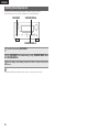
z
z
z
z
Wall
Wand
Paroi
Parete
Pared
Muur
Vägg
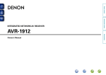
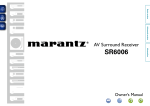
zzFor proper heat dispersal, do not install this unit in a
confined space, such as a bookcase or similar enclosure.
•More than 0.3 m is recommended.
•Do not place any other equipment on this unit.
zzStellen Sie das Gerät nicht an einem geschlossenen Ort,
wie in einem Bücherregal oder einer ähnlichen Einrichtung
auf, da dies eine ausreichende Belüftung des Geräts
behindern könnte.
•Empfohlen wird über 0,3 m.
•Keine anderen Gegenstände auf das Gerät stellen.
zzPour permettre la dissipation de chaleur requise, n’installez
pas cette unité dans un espace confiné tel qu’une
bibliothèque ou un endroit similaire.
•Une distance de plus de 0,3 m est recommandée.
•Ne placez aucun matériel sur cet appareil.
zzPer una dispersione adeguata del calore, non installare
questa apparecchiatura in uno spazio ristretto, come ad
esempio una libreria o simili.
•Si raccomanda una distanza superiore ai 0,3 m.
•Non posizionare alcun altro oggetto o dispositivo su questo
dispositivo.
zzPara la dispersión del calor adecuadamente, no instale
este equipo en un lugar confinado tal como una librería o
unidad similar.
•Se recomienda dejar más de 0,3 m alrededor.
•No coloque ningún otro equipo sobre la unidad.
zzPlaats dit toestel niet in een kleine afgesloten ruimte, zoals
een boekenkast e.d., omdat anders de warmte niet op
gepaste wijze kan worden afgevoerd.
•Meer dan 0,3 m is aanbevolen.
•Plaats geen andere apparatuur op het toestel.
zzFör att tillförsäkra god värmeavledning får utrustningen
inte installeras i instängda utrymmen, som t.ex. en
bokhylla eller liknande.
•Mer än 0,3 m rekommenderas.
•Placera ingen annan utrustning ovanpå den här enheten.
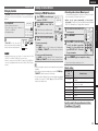
ENGLISH
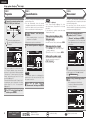
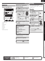
Simple version
Getting started
Thank you for purchasing this DENON product. To ensure proper operation, please read these owner’s manual carefully before using the product.
After reading them, be sure to keep them for future reference.
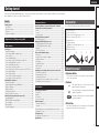
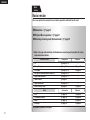
Contents
Simple version (Simple setup guide)···························3
Basic version· ·········································································12
Information· ············································································71
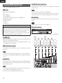
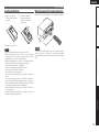
Check that the following parts are supplied with the product.
qOwner’s manual....................................................................... 1
wService network list.................................................................. 1
ePower cord (Cord length: Approx. 1.7 m)................................. 1
rRemote control unit (RC-1146)................................................. 1
tR6/AA batteries........................................................................ 2
ySetup microphone
(DM-A409, Cord length: Approx. 6.0 m)................................... 1
uAM loop antenna...................................................................... 1
iFM indoor antenna................................................................... 1
r
e
y
u
i
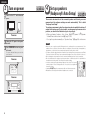
About this manual
nnOperation buttons
The operations described in this manual are based mainly on
remote control operation.
nnSymbols
v
This symbol indicates a reference page on which
related information is described.
This symbol indicates a supplementary information
and tips for operations.
NOTE
This symbol indicates points to remember operations
or function limitations.
nnIllustrations
Note that the illustrations in these instructions are for explanation
purposes and may differ from the actual unit.
1
Information
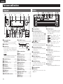
Part names and functions···························································72
Front panel···················································································72
Display·························································································72
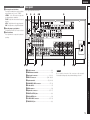
Rear panel····················································································73
Remote control unit·····································································74
Other information········································································76
Trademark information·································································76
Surround······················································································77
Relationship between video signals and monitor output·············81
Explanation of terms····································································82
Troubleshooting···········································································84
Resetting the microprocessor·····················································86
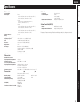
Specifications···············································································87
Accessories
Advanced version
Connections··················································································13
Important information··································································13
Connecting an HDMI-compatible device·····································14
Connecting a TV··········································································15
Connecting a DVD player·····························································16
Connecting a set-top box (Satellite tuner/cable TV)·····················16
Connecting a digital video recorder·············································17
Connecting a digital camcorder···················································17
Connecting a control dock for iPod··············································18
Connecting an iPod or USB memory device to the USB Port·····18
Connecting a CD player·······························································19
Connecting an antenna································································19
Connecting a external power amplifier········································20
Connecting an external control device·········································20
Playback (Basic operation)··························································21
Important information··································································21
Playing a Blu-ray Disc player/DVD player·····································22
Playing a CD player······································································22
Playing an iPod®· ········································································22
Tuning in radio stations································································25
Playing a USB memory device·····················································28
Selecting a listening mode (Surround mode)···························29
Standard playback········································································29
DENON original surround playback··············································31
Stereo playback···········································································31
Direct playback············································································31
Pure direct playback····································································31
Advanced version ·······························································32
Speaker installation/connection (Other than 7.1-channel
system with surround back speakers)·······································33
Install···························································································33
Connect·······················································································34
Set up speakers···········································································37
Playback (Advanced operation)··················································39
Convenient functions···································································39
Playback in ZONE2 (Separate room) ·········································42
q ZONE2 playback by speaker output········································42
w ZONE2 playback by audio output············································42
Playback·······················································································43
Quick select function···································································43
How to make detailed settings···················································44
Menu map···················································································44
Examples of menu and front display···········································45
Inputting characters ····································································46
Input Setup··················································································47
Audio/Video Adjust······································································52
Manual Setup··············································································58
Information··················································································66
Operating the connected devices by remote control unit·······67
Operating AV equipment·····························································67
Registering preset codes·····························································67
Operating components································································70
Specifying the zone used with the remote control unit···············71
Resetting the remote control unit················································71
Basic version
Getting started···············································································1
Accessories···················································································1
About this manual··········································································1
Features·························································································2
Cautions on handling·····································································2
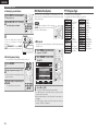
ENGLISH
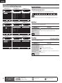
Features
Fully Discrete, identical quality and power for all
7 channels (135 W x 7ch)
The unit is equipped with a power amplifier that reproduces highfidelity sound in surround mode with equal quality and power for all
channels, true to the original sound.
The power amplifier circuit adopts a discrete-circuit configuration
that achieves high-quality surround sound reproduction.
Supports HDMI 1.4a with 3D, ARC, Deep Color,
x.v.Color , Auto Lipsync and HDMI control function
This unit can output 3D video signals input from a Blu-ray Disc
player to a TV that supports a 3D system. This unit also supports
the ARC (Audio Return Channel) function, which reproduces TV
sound with this unit via an HDMI cable used for connecting the
unit and a TVz.
zThe
z
TV should support the ARC function.
6-HDMI inputs and 1-output
The unit is equipped with 6 HDMI input connectors for connecting
devices with HDMI connectors, such as a Blu-ray Disc player,
game machine, HD video camera, etc.
High definition audio support
The unit is equipped with a decoder which supports high-quality
digital audio format for Blu-ray Disc players such as Dolby TrueHD,
DTS-HD Master Audio, etc.
Dolby Pro Logic gz
The unit is provided with a Dolby Pro Logic gz decoder. When you
reproduce the sound in Dolby Pro Logic gz playback with front
height speakers connected to the unit, you can enjoy playback
sound with rich spacial expression.
Easy to use, Graphical User Interface
Simple settings are enabled with the setting menus displayed on
the TV screen. When you control the sound volume, the volume
level is displayed on the screen, and when you switch the input
source, the name of the input source is displayed.
2
Cautions on handling
Auto setup function
The unit is provided with an “Auto setup function” which
automatically makes speaker settings best suited for the listening
environment. The sound from the speakers is picked up with the
supplied microphone. Reflecting sound and audio characteristics of
speakers are measured, and settings for an optimum sound field
are automatically made.
All sources are up-scaled to 1080p
The unit is provided with an HDMI video upscaling function that
converts an analog video signal input to the unit to a 1080p (HD
resolution) signal and supplies it to a TV via the HDMI connector.
This enables the unit and a TV connected with a single HDMI cable
and any video source to be reproduced precisely with HD level of
quality.
Direct play for iPod® and iPhone® via USB
Music data from an iPod can be played back if you connect the
USB cable supplied with the iPod via the USB port of this unit, and
also an iPod can be controlled with the remote control unit for this
unit.
When an iPod is connected, merely pressing iPod PLAY on the
main unit or remote control unit starts playback of music from the
iPod.
•Before turning the power switch on
Check once again that all connections are correct and that there are
no problems with the connection cables.
•Power is supplied to some of the circuitry even when the unit is
set to the standby mode. When going on vacation or leaving home
for long periods of time, be sure to unplug the power cord from the
power outlet.
•About Condensation
If there is a major difference in temperature between the inside of
the unit and the surroundings, condensation (dew) may form on
the operating parts inside the unit, causing the unit not to operate
properly.
If this happens, let the unit sit for an hour or two with the power
turned off and wait until there is little difference in temperature
before using the unit.
•Cautions on using mobile phones
Using a mobile phone near this unit may result in noise. If that
occurs, move the mobile phone away from this unit when it is in use.
•Moving the unit
Turn off the power and unplug the power cord from the power
outlet. Next, disconnect the connection cables to other system units
before moving the unit.
•About Care
•Wipe the cabinet and control panel clean with a soft cloth.
•Follow the instructions when using a chemical cleaner.
•Benzene, paint thinner or other organic solvents as well as
insecticide may cause material changes and discoloration if brought
into contact with the unit, and should therefore not be used.
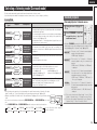
ENGLISH
1
2
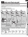
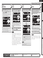
Install
(vpage 4)
3
Connect
(vpage 4)
4
Turn on
power
Enjoy better audio, using
the correct install method.
Connect 7.1-channel
speakers, a TV and Bluray Disc player equipped
with an HDMI connector.
Set up
speakers
Play back
disc
Use the setup microphone
(DM-A409) included with
the product, for automatic
setup.
Enjoy Blu-ray Disc and DVD
in surround sound.
(vpage 6)
(vpage 11)
Advanced version
(vpage 6)
5
Information
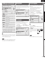
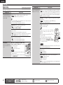
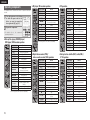
Set up speakers (Audyssey® Auto Setup)
STEP 1
Preparation
STEP 2
Speaker
Detection
STEP 3
Measurement
STEP 4
Calculation
STEP 5
Check
STEP 6
Store
Basic version
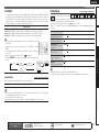
Here, we explain the entire setup procedure, from unboxing the unit to using it in a home theater.
The “Simple version” section provides the speaker installation, connection, and setup methods for the 7.1-channel system with surround
back speakers. For the installing, connecting, and setup methods of speakers other than the 7.1-channel system (with surround back
speakers), see page 33.
nnBefore connecting the unit, turn off the power to all devices.
nnFor operation of the connected devices, refer to the user manuals for each device.
Simple version
Simple version (Simple setup guide)
Simple
version
Finish
3
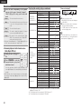
ENGLISH
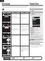
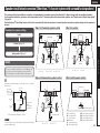
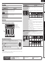
1 Install
1
2
3
4
5
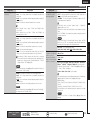
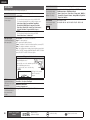
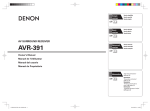
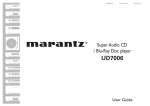
This unit can perform 2.0/2.1 to 7.1-channel surround playback.
This page provides the speaker installation procedure for the
7.1-channel playback using surround back speakers as an example.
The default setting is 7.1-channel. You can also perform 5.1-channel playback.
To perform 5.1-channel playback, connect5.1-channel speakers only.
Use the Audyssey Auto Setup function of this unit to automatically detect the
number of connected speakers and perform optimal settings for the speakers
to be used.
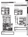
2 Connect
Speakers
Carefully check the left (L) and right (R)
channels and + (red) and – (black) polarities
on the speakers being connected to the
this unit, and be sure to interconnect the
channels and polarities correctly.
Connecting the speaker cables
Peel off about 10 mm of sheathing from the tip
of the speaker cable, then either twist the core
wire tightly or terminate it.
FL
FR
SW
C
1
Speaker terminals
Speaker
impedance
FRONT
CENTER
SURROUND
SURR. BACK / AMP ASSIGN
6 – 16 Ω
SR
Listening
position
SBL
FL
FR
C
SW
SL
SR
SBL
SBR
Front speaker (L)
Front speaker (R)
Center speaker
Subwoofer
Surround speaker (L)
Surround speaker (R)
Surround back speaker (L)
Surround back speaker (R)
SBR
•Install the surround speakers in a position 60
to 90 cm higher than ear level.
Front
speaker
Surround
speaker
60 – 90 cm
Surround back
speaker
•Point slightly
downwards
GViewed from the sideH
4
4
5
NOTE
135 – 150˚
SL
3
•Connect so that the speaker cable core wires
do not protrude from the speaker terminal.
The protection circuit may be activated if the
core wires touch the rear panel or if the + and –
sides touch each other (vpage 83 “Protection
Circuit”).
•Never touch the speaker terminals while the
power supply is connected. Doing so could
result in electric shock.
•Use speakers with the speaker impedances
shown below.
22 – 30˚
90 – 110˚
2
The “Simple version” section provides the speaker installation, connection, and setup methods for the 7.1-channel system with surround back speakers.
For the installing, connecting, and setup methods of speakers other than the 7.1-channel system (with surround back speakers), see page 33.
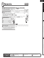
ENGLISH
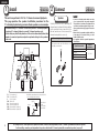
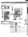
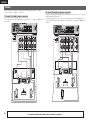
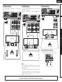
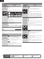
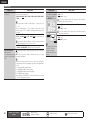
Blu-ray Disc player and TV
TV
Basic version
Use only an HDMI (High Definition Multimedia Interface) cable that bears the HDMI
logo (a certified HDMI product). Using a cable without the HDMI logo (an uncertified
HDMI product) may result in abnormal playback.
When outputting Deep Color or 1080p, etc., we recommend you use a “High Speed
HDMI cable” or a “High Speed HDMI cable with Ethernet” for enhanced high-quality
playback.
Simple version
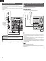
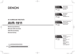
Connect
Blu-ray Disc player
Audio cable
(sold separately)
FL
SW
HDMI
IN
HDMI cable
(sold separately)
FR
Advanced version
HDMI
OUT
HDMI cable
(sold separately)
C
Subwoofer
with built-in
amplifier
Speaker cables
(sold separately)
SL
SR
SBL
SBR
Information
To household power outlet
(AC 230 V, 50 Hz)
Power cord
(supplied)
NOTE
•Do not plug in the power cord until all connections have been completed.
•Do not bundle power cords together with connection cables. Doing so can result in humming or noise.
The “Simple version” section provides the speaker installation, connection, and setup methods for the 7.1-channel system with surround back speakers.
For the installing, connecting, and setup methods of speakers other than the 7.1-channel system (with surround back speakers), see page 33.
5
ENGLISH
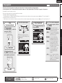
3 Turn on power
1
Turn on the TV and subwoofer
power.
Power on
the TV input to the input of
2 Change
this unit.
POWER ON to turn on power
3 Press
to the unit.
The power indicator flashes green and the
power turns on.
Power on
Power on
6
1
2
3
4
5
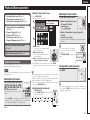
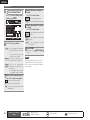
4 Set up speakers
(Audyssey® Auto Setup)
1
2
3
4
5
The acoustic characteristics of the connected speakers and listening room are
measured and the optimum settings are made automatically. This is called
“Audyssey Auto Setup”.
To perform measurement, place the setup microphone in multiple locations all
around the listening area. For best results, we recommend you measure in six
positions, as shown in the illustration (up to six positions).
•• When performing Audyssey Auto Setup, MultEQ®/Dynamic EQ®/Dynamic
Volume® functions become active (vpage 55, 56).
•• To set up the speakers manually, use “Speaker Setup” (vpage 58) on the menu.
NOTE
•Make the room as quiet as possible. Background noise can disrupt the room measurements. Close
windows, silence cell phones, televisions, radios, air conditioners, fluorescent lights, home appliances,
light dimmers, or other devices as measurements may be affected by these sounds.
•Cell phones should be placed away from all audio electronics during the measurement process as Radio
Frequency Interference (RFI) may cause measurement disruptions (even if the cell phone is not in use).
•Do not unplug the setup microphone from the main unit until Audyssey Auto Setup is completed.
•Do not stand between the speakers and setup microphone or allow obstacles in the path while the
measurements are being made. This will cause inaccurate readings.
•Loud test sounds may be played during Audyssey Auto setup. This is part of
normal operation. If there is background noise in room, these test signals will
increase in volume.
•Operating VOL df during the measurements will cancel the measurements.
•Measurement cannot be performed when headphones are connected.
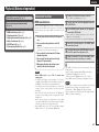
ENGLISH
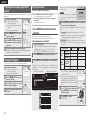
Set up speakers (Audyssey® Auto Setup)
GExample qH
GExample wH
FL SW C
FL SW C
FR
( : Measuring positions)
SBL
SL
SR
SBL
SBR
nn Set up the zone mode
Press ZONE SELECT to switch the zone mode to
“MAIN”.
The “MAIN” indicator lights.
Setup
microphone
FR
*M
SL
SBR
FL Front speaker (L)
FR Front speaker (R)
C Center speaker
SW Subwoofer
Sound receptor
( : Measuring positions)
SR
SBL
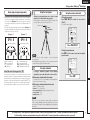
When placing the setup microphone, adjust the height of the
sound receptor to the level of the listener’s ear.
Set up the remote control unit
Press ZONE SELECT
SR
SBR
Surround speaker (L)
Surround speaker (R)
Surround back speaker (L)
Surround back speaker (R)
About the main listening position (*M)
The main listening position is the position where listeners would
normally sit or where one would normally sit alone within the listening
environment. Before starting Audyssey Auto Setup, place the setup
microphone in the main listening position. Audyssey MultEQ® uses
the measurements from this position to calculate speaker distance,
level, polarity, and the optimum crossover value for the subwoofer.
NOTE
•Do not hold the setup microphone in your hand during
measurements.
•Avoid placing the setup microphone close to a seat back or wall as
sound reflections may give inaccurate results.
2 If
nn Set up the operation mode
Press AMP to set the remote control unit to amplifier
operation mode.
Set up the subwoofer
using a subwoofer capable of the following
adjustments, set up the subwoofer as shown below.
nn When using a subwoofer with a direct mode
Advanced version
*M
SL
Mount the setup microphone on a tripod or stand
and place it in the main listening position.
3
Basic version
•Measurements are performed by placing the setup microphone
successively at multiple positions throughout the entire listening
area, as shown in GExample qH. For best results, we recommend
you measure in six positions, as shown in the illustration (up to six
positions).
•Even if the listening environment is small as shown in GExample wH,
measuring at multiple points throughout the listening environment
results in more effective correction.
Set up the microphone
Simple version
1
About setup microphone placement
Press AMP
Set the direct mode to “On” and disable the volume adjustment
and crossover frequency setting.
nn When using a subwoofer without a direct mode
Information
Make the following settings:
•Volume : “12 o’clock position”
•Crossover frequency : “Maximum/Highest Frequency”
•Low pass filter : “Off”
•Standby mode : “Off”
NOTE
When you use two subwoofers, please adjust the subwoofer
volume controls individually so that each subwoofer level is as close
as possible to 75 dB using the test tone (vpage 60) before Audyssey
Auto Setup.
The “Simple version” section provides the speaker installation, connection, and setup methods for the 7.1-channel system with surround back speakers.
For the installing, connecting, and setup methods of speakers other than the 7.1-channel system (with surround back speakers), see page 33.
7
ENGLISH
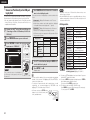
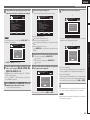
Set up speakers (Audyssey® Auto Setup)
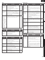
STEP 1
STEP 2
Preparation
4
Speaker Detection
Connect the setup microphone to the
SETUP MIC jack of this unit.
When the setup microphone is
connected, the following screen is
displayed.
AUTO SETUP
AUDYSSEY AUTO SETUP
MultEQ
ENTER
and then press
RETURN Cancel
This screen provides the method for setting
up 7.1-channel playback using surround back
speakers. For the method of setting up speakers
other than the 7.1-channel system, select “Amp
Assign” and perform step 3 and 4 of “Set up
speakers” (vpage 37).
If unused channels are set with “Channel Select”,
measuring time can be shortened. For setting,
perform steps 5 to 9 of “Set up speakers”
(vpage 38).
If “Caution” is displayed:
Go to “Error messages” (vpage 10), check
any related items, and perform the necessary
procedures.
If the problem is resolved, return and restart
“Audyssey Auto Setup”.
When performing Audyssey Auto
Setup over again
Press ui to select “Retry”, and then press ENTER.
7 The detected speakers are displayed.
qPress RETURN, to the “Cancel Auto Setup?”
AUTO SETUP
AUDYSSEY AUTO SETUP
Retry
Next
When measuring has stopped
prompt is displayed.
wPress o to select “Yes”, then press ENTER.
MultEQ
STEP2 Spkr Detect Check
Front
Yes
Center
Yes
Subwoofer
Yes
Surround
Yes
S.Back
Yes
Enter
NOTE
When measuring begins, a test tone is
output from each speaker.
•Measurement requires several minutes.
[1/6]
STEP1 Preparation
Connect the speakers
and place them according to the recommendations in the manual.
Set the following
items if necessary.
Amp Assign
Channel Select
Auto Setup Start
Measurement
•In STEP 2, you will perform measurements at the
main listening position.
•This step automatically checks the speaker
configuration and speaker size, and calculates the
channel level, distance, and crossover frequency.
It also corrects distortion in the listening area.
“Measure”
6 Select
ENTER.
Start Auto Setup
STEP 3
[2/6]
Setting up the speakers again
Repeat the operation from step 4 of
STEP 1 Preparation .
Measurement
•In STEP 3, you will perform measurements at
multiple positions (two to six positions) other than
the main listening position.
•You can achieve a more effective correction of
distortion within the listening area by performing
measurements at multiple positions.
the setup microphone to
9 Move
position 2, use ui to select
“Measure”, and then press ENTER.
The measurement of the second position
starts. Measurements can be made in up to
six positions.
AUTO SETUP
AUDYSSEY AUTO SETUP
Measure
Next
Calculation
ENTER Enter
RETURN Cancel
Start next measurement. Test Tone will start
If you want to omit measurements from the next
position onward, select “Next 1 Calculation”.
(Go to STEP4 Calculation
)
NOTE
If a connected speaker is not displayed, the
speaker may not be connected correctly. Check
the speaker connection.
step 9, measuring positions 3
10 Repeat
to 6.
Use ui to select “Next 1
8 Measurement”
and then press ENTER.
When measurement of position 6 is
completed, a “Measurements finished.”
message is displayed.
AUTO SETUP
AUDYSSEY AUTO SETUP
STEP3 Measurement
Measurements finished.
Retry
Next
Move the cursor
(Up/Down/Left/Right)
Confirm the setting
MultEQ
[3/6]
Calculation
ENTER Enter
Proceed to Step 4 (Analyze)
Remote control operation
buttons
[3/6]
ENTER Enter
RETURN Cancel
Go to Step 3 (Measurement) after speaker check
Use ui to select “Auto Setup Start”
5 and
then press ENTER.
8
MultEQ
STEP3 Measurement
Please place the microphone at ear height
at 2nd listening
position.
Return to previous menu
RETURN Cancel
ENGLISH
Set up speakers (Audyssey® Auto Setup)
STEP 5
Calculation
STEP 6
Check
Finish
Store
Unplug the setup microphone from
Select “Store” and then press ENTER.
Use ui to select the item you want
the
screen, use ui
11 On
12
14
15
the unit’s SETUP MIC jack.
to
check,
and
then
press
ENTER
.
to select “Next 1 Calculation”, and
®
then press ENTER.
16 Set Dynamic Volume .
STEP 3
Save the measurement results.
STEP4 Calculation
Now calculating...
Please wait.
[4/6]
Next
ENTER
Enter
RETURN Cancel
AUTO SETUP
AUDYSSEY AUTO SETUP
ENTER Enter
Apply and store measurement result
MultEQ
Finish
Storing complete.
Auto Setup is now
finished. Please unplug
microphone.
RETURN Cancel
[6/6]
Turn on Dynamic Volume?
Yes
No
ENTER Exit
Turn Dynamic Volume on and exit Auto Setup
AUTO SETUP
AUDYSSEY AUTO SETUP
STEP6 Store
Now storing...
Please wait.
MultEQ
[6/6]
25%
•For details of Dynamic Volume settings, see
page 56.
nn When turning Dynamic Volume on
•Use o to select “Yes”, and then press ENTER.
The unit automatically enters “Evening” mode.
nn When turning Dynamic Volume off
NOTE
•Saving the results requires about 10 seconds.
•If the measuring results are not to be saved,
press RETURN. A message “Cancel Auto
Setup?” will be displayed. Press o then select
“Yes”. All the measured Audyssey Auto Setup
data will be erased.
NOTE
After performing Audyssey Auto Setup, do not
change the speaker connections or subwoofer
volume. In event of a change, perform Audyssey
Auto Setup again.
NOTE
During saving of measurement results, be sure
not to turn off the power.
Confirm the setting
Information
Move the cursor
(Up/Down/Left/Right)
•Use p to select “No”, and then press ENTER.
Advanced version
Use ui to select “Next 1 Store”
and then press ENTER.
•If the result differs from the actual connection
status, or if “Caution!” is displayed, see “Error
messages” (vpage 10). Then carry out Audyssey
Auto Setup again.
•If the result still differs from the actual connection
status after remeasurement or the error message
still appears, it is possible that the speakers
are not connected properly. Turn this unit off,
check the speaker connections and repeat the
measurement process from the beginning.
•If you change speaker positions or orientation,
perform Audyssey Auto Setup again to find the
optimal equalizer settings.
Remote control operation
buttons
[6/6]
Store
•Subwoofers may measure a greater reported
distance than the actual distance due to added
electrical delay common in subwoofers.
•If you want to check another item, press
RETURN.
13
MultEQ
STEP6 Store
Press “Store” to store
calculation results.
Store
Select item to check
25%
•Analysis takes several minutes to complete. The
time required for this analysis depends on the
number of speakers connected.
The more connected speakers there are, the
longer it takes to perform analysis.
[5/6]
STEP5 Check
Check processing results. To proceed,press
“Next”
Spkr Config Check
Distance Check
Ch. Level Check
Crossover Check
MultEQ
AUTO SETUP
AUDYSSEY AUTO SETUP
MultEQ
Basic version
AUTO SETUP
AUDYSSEY AUTO SETUP
Measuring results are analyzed, and the
frequency response of each speaker in the
listening room is determined.
AUTO SETUP
AUDYSSEY AUTO SETUP
Simple version
STEP 4
Return to previous menu
9
ENGLISH
Error messages
Parameter Check
An error message is displayed if Audyssey® Auto Setup could not be completed due to speaker placement, the measurement environment, etc.
If this happens, check the relevant items, be sure to take the necessary measures, then perform Audyssey Auto Setup over again.
This function enables you to check the measurement results and
equalizer characteristics after Audyssey Auto Setup.
NOTE
Be sure to turn off the power before checking speaker connections.
Examples
AUTO SETUP
AUDYSSEY AUTO SETUP
Error details
MultEQ
Caution!
No microphone or Speaker
Measures
•The connected setup microphone is broken, •Connect the included setup microphone to
or a device other than the supplied setup the SETUP MIC jack of this unit.
microphone is connected.
•Not all speakers could be detected.
•The front L speaker was not properly •Check the speaker connections.
detected.
Use ui to select “Parameter Check” and then
1 press
ENTER.
Use ui to select the item you want to check, then
2 press
ENTER or p.
Measurement results for each speaker are displayed.
AUTO SETUP
PARAMETER CHECK
Speaker Config Check
Distance Check
Channel Level Check
Crossover Check
EQ Check
Retry
Check cause of problem!
AUTO SETUP
AUDYSSEY AUTO SETUP
RETURN Cancel
MultEQ
Caution!
Ambient noise is too high
or Level is too low
Retry
Check cause of problem!
AUTO SETUP
AUDYSSEY AUTO SETUP
Restore
•There is too much noise in the room for •Either turn off any device generating noise or
accurate measurements to be made.
move it away.
•Perform again when the surroundings are
quieter.
•Speaker or subwoofer sound is too low for •Check the speaker installation and the
accurate measurements to be made.
direction in which the speakers are facing.
•Adjust the subwoofer’s volume.
Speaker Config. Check
Distance Check
•The displayed speaker could not be detected. •Check the connections of the displayed
speaker.
Caution!
Front R
None
Check the speaker configuration.
Check the distance.
Channel Level Check
Check the channel level.
Crossover Check
RETURN Cancel
MultEQ
Show speaker configuration result
Check the crossover frequency.
EQ Check
Check the equalizer.
•If “EQ Check” is selected in step 2, press ui to select equalizing
curve (“Audyssey” or “Audyssey Flat”) to be checked.
Use o p to switch the display between the different speakers.
3 Press RETURN.
The confirmation screen reappears. Repeat step 2.
Retry
Check cause of problem!
AUTO SETUP
AUDYSSEY AUTO SETUP
Retrieving Audyssey Auto Setup settings
RETURN Cancel
MultEQ
Caution!
Front L
Phase
•The displayed is connected with the polarities •Check the polarities of the displayed speaker.
reversed.
•For some speakers, this error message may
be displayed even if the speaker is properly
connected. If you are sure the connection is
correct, press ui to select “Skip”, then
press ENTER.
If you set “Restore” to “Yes”, you can return to Audyssey Auto Setup
measurement result (value calculated at the start by MultEQ®) even
when you have changed each setting manually.
Retry
Skip
Check cause of problem!
10
RETURN Cancel
Remote control operation
buttons
Move the cursor
(Up/Down/Left/Right)
Confirm the setting
Return to previous menu
ENGLISH
Make the necessary settings on the
player (language setting, subtitles
setting, etc.) beforehand.
3
Adjust the sound volume.
2
3
4
5
When power is switched to standby
Press POWER OFF.
GPower indicator status in standby modeH
•Normal standby : Off
•When “HDMI Control” is set to “ON” : Red
Basic version
1
the component connected to
2 Play
this unit.
Press BD to switch an input source
for a player used for playback.
1
Simple version
5 Play back disc
You can also switch the power to standby by
pressing ON/STANDBY on the main unit.
VOL d············································ Volume up
VOL f······································· Volume down
MUTE··················································· Muting
NOTE
Set the listening mode according to the playback contents
(cinema, music, etc.) or according to your liking (vpage 29
“Selecting a listening mode (Surround mode)”).
Advanced version
4 Set the listening mode.
During power standby, a minimal amount of power is consumed. To
totally cut off the power, remove the power cord from the power
outlet.
Information
Remote control operation
buttons
Move the cursor
(Up/Down/Left/Right)
Confirm the setting
Return to previous menu
11
ENGLISH
Basic
version
Basic version
Here, we explain the connections and basic operation methods for this unit.
F Connections vpage 13
F Playback (Basic operation) vpage 21
F Selecting a listening mode (Surround mode) vpage 29
nnRefer to the pages indicated below for information on connecting and playing back the various
media and external devices.
Audio and video
Playback
TV
vpage 14, 15
Blu-ray Disc player
vpage 14
vpage 22
DVD player
vpage 14, 16
vpage 22
Set-top box (Satellite tuner or cable TV)
vpage 14, 16
–
Digital video recorder
vpage 14, 17
–
Game console
vpage 14
–
Digital camcorder
vpage 14, 17
–
Control dock for iPod
vpage 18
Audio
Connection
–
vpage 22
Playback
iPod®
vpage 18
vpage 24
USB memory device
vpage 18
vpage 28
Radio
vpage 19
vpage 25
CD player
vpage 19
vpage 22
For speaker connections, see page 4.
12
Connection
ENGLISH
Simple version
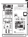
Connections
Important information
•Make connections as follows before using this unit. Select an appropriate connection type
according to the components to be connected.
•You may need to make some settings on this unit depending on the connection method. Refer to
each description for more information.
•Select the cables (sold separately) according to the components being connected.
NOTE
Converting input video signals for output (Video conversion function)
This unit is equipped with four types of video input connectors (HDMI, Component video, S-Video and
video) and two types of video output connectors (HDMI, Component video and video).
Use the connectors corresponding to the components to be connected.
This function automatically converts various formats of video signals input to this unit into the formats used
to output the video signals from this unit to a monitor.
GFlow of video signals for MAIN ZONEH
This unit
Monitor
Output
Input
(IN)
Output
(MONITOR OUT)
HDMI connector
HDMI connector
HDMI
connector
Component video
connectors
Component video
connectors
S-Video connector
Video connector
Video connector
HDMI connector
NOTE
•HDMI signals cannot be converted into analog signals.
•When a non-standard video signal from a game machine or some other source is input, the video
conversion function might not operate.
•Component video input signals cannot be converted into Video format.
•A menu is output via the HDMI connector or component video connector.
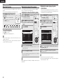
Examples of on-screen display
•Menu screen
Component video
connectors
When the volume is adjusted
MENU
Audio/Video Adjust
Information
Auto Setup
Manual Setup
Input Setup
Video connector
Video connector
Adjust various audio and video parameters
Input
BD
Mode
STEREO
Auto
Master Volume
-80.0dB
Status display: The operating status appears briefly on the screen
when the input source is switched or the volume is
changed.
in Set as Necessary
•Set when not using the video conversion function.
“Video Convert” (vpage 50)
•Set when changing the resolution of the video signal.
“Resolution” (vpage 51)
•Status display screen
When the input source is
switched
NOTE
•If you operate the menu while playing back 3D video content, the playback video is replaced by the menu
screen. The playback video is not displayed behind the menu screen.
•This unit does not show the status display while playing back 3D video content.
13
Information
S-Video connector
Component video
connectors
Input
•The video conversion function supports the NTSC, PAL, SECAM, NTSC 4.43, PAL-N, PAL-M and PAL-60
formats.
•The resolution of the video signal input to this unit’s HDMI connector is the one set at “Resolution”
(vpage 51) (1080p HDMI signals and 1080p component signals are output at 1080p, regardless of the
setting).
•Resolutions of HDMI-compatible TVs can be checked at “HDMI Monitor Information” (vpage 66).
Advanced version
Video device
Basic version
•Do not plug in the power cord until all connections have been completed.
•When making connections, also refer to the operating instructions of the other components being
connected.
•Be sure to connect the left and right channels properly (left with left, right with right).
•Do not bundle power cords together with connection cables. Doing so can result in noise.
ENGLISH
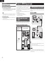
Connecting an HDMI-compatible device
You can connect up to six HDMI-compatible devices to the unit.
HDMI function
NOTE
This unit supports the following HDMI functions:
•3D
•Deep Color (vpage 82)
•Auto Lip Sync (vpage 61)
•x.v.Color, sYCC601 color, Adobe RGB color, Adobe YCC601color (vpage 82, 83)
•High definition digital audio format
•ARC (Audio Return Channel)
•Content Type
•CEC (HDMI control)
Copyright protection system
In order to play back digital video and audio such as BD-Video or DVD-Video via HDMI connection, both
this unit and TV or the player need to support the copyright protection system known as HDCP (Highbandwidth Digital Content Protection System). HDCP is copyright protection technology comprised of
data encryption and authentication of the connected AV device. This unit supports HDCP.
•If a device that does not support HDCP is connected, video and audio are not output correctly. Read
the owner’s manual of your television or player for more information.
About HDMI cables
•When a device supporting Deep Color signal transfer is connected, use a cable compatible “High Speed
HDMI cable” or “High Speed HDMI cable with Ethernet”
•When the ARC function is used, connect a device with a ”Standard HDMI cable with Ethernet” or “High
Speed HDMI cable with Ethernet” for HDMI 1.4a.
HDMI control function (vpage 39)
This function allows you to operate external devices from the receiver and operate the receiver from
external devices.
NOTE
•The HDMI control function may not work depending on the device it is connected to and its settings.
•You cannot operate a TV or Blu-ray Disc player / DVD player that is not compatible with the HDMI control
function.
About 3D function
This unit supports input and output of 3D (3 dimensional) video signals of the HDMI 1.4a standards. For
playing the 3D video content, a player, and a TV that support the 3D function of the HDMI 1.4a standards
are required in addition to this unit.
NOTE
•If you operate the menu while playing back 3D video content, the playback video is replaced by the menu
screen. The playback video is not displayed behind the menu screen.
•This unit does not show the status display while playing back 3D video content.
14
About ARC (Audio return channel) function
The Audio Return Channel in HDMI 1.4a enables a TV, via a single HDMI cable, to send audio data
“upstream” to this unit.
•To enable the ARC function, set “HDMI Control” to “ON” (vpage 61).
•When connecting a TV that does not support the ARC function, a separate connection using an audio
cable is required. In this case, refer to “Connecting a TV” (vpage 15) for the connection method.
About Content Type
The HDMI Specification Version 1.4a enables simple, automated picture setting selection with no user
intervention.
NOTE
To enable the Content Type, set “Video Mode” to “Auto” (vpage 50).
Cables used for connections
Audio and video cable (sold separately)
HDMI cable
•This interface allows transfer of digital video signals and digital audio signals over a single HDMI cable.
Blu-ray
Disc
player
DVD
player
Set-top
box
Digital
video
recorder
Game
console
Digital
camcorder
TV
HDMI
OUT
HDMI
OUT
HDMI
OUT
HDMI
OUT
HDMI
OUT
HDMI
OUT
HDMI
IN
ENGLISH
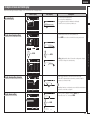
Connecting an HDMI-compatible device
To listen to TV audio through this device, use the optical digital connection.
The audio signal from the HDMI output connector (sampling frequency, number of channels, etc.) may be
limited by the HDMI audio specifications of the connected device regarding permissible inputs.
Connecting to a device equipped with a DVI-D connector
Cables used for connections
When an HDMI/DVI conversion cable (sold separately) is used, the HDMI video signals are converted to
DVI signals, allowing connection to a device equipped with a DVI-D connector.
Video cable (sold separately)
Video cable
(Yellow)
NOTE
(Green)
Component video
cable
(Blue)
(Red)
Advanced version
•No sound is output when connected to a device equipped with a DVI-D connector. Make separate audio
connections.
•Signals cannot be output to DVI-D devices that do not support HDCP.
•Depending on the combination of devices, the video signals may not be output.
Audio cable (sold separately)
Optical cable
nnSettings related to HDMI connections
Set as necessary. For details, see the respective reference pages.
Input Assign (vpage 49)
Set this to change the HDMI input connector to which the input source is assigned.
Basic version
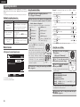
NOTE
This connection is not required when a TV compatible with the ARC function (Audio Return Channel (HDMI
1.4a standard function)) is connected to this unit via an HDMI connection.
For details, see “About ARC (Audio return channel) function” (vpage 14) or refer to the instruction manual
for your TV.
NOTE
Simple version
•When this unit is connected to other devices with HDMI cables, connect this unit and TV also with an
HDMI cable.
•When connecting a device that supports Deep Color transmission, please use a “High Speed HDMI
cable” or “High Speed cable with Ethernet”.
•Video signals are not output if the input video signals do not match the monitor’s resolution. In this case,
switch the Blu-ray Disc/DVD player’s resolution to a resolution with which the monitor is compatible.
•When this unit and monitor are connected with an HDMI cable, if the monitor is not compatible with
HDMI audio signal playback, only the video signals are output to the monitor.
Connecting a TV
•Select the connector to use and connect the device.
•For video connections, see “Converting input video signals for output (Video conversion function)”
(vpage 13).
•For instructions on HDMI connections, see “Connecting an HDMI-compatible device” (vpage 14).
TV
AUDIO
VIDEO
COMPONENT VIDEO
IN
Y
PB PR
VIDEO
IN
OPTICAL
OUT
HDMI Setup (vpage 61)
Information
Make settings for HDMI video/audio output.
•RGB Range
•Auto Lip Sync
•HDMI Audio Out
•HDMI Control
•Standby Source
•Power Off Control
NOTE
The audio signals output from the HDMI connectors are only the HDMI input signals.
in Set as Necessary
Set this to change the digital input connector to which the input source is assigned.
“Input Assign” (vpage 49)
15
ENGLISH
Connecting a DVD player
Connecting a set-top box (Satellite tuner/cable TV)
•You can enjoy video and audio from a DVD.
•Select the connector to use and connect the device.
•For instructions on HDMI connections, see “Connecting an HDMI-compatible device” (vpage 14).
•You can watch satellite or cable TV.
•Select the connector to use and connect the device.
•For instructions on HDMI connections, see “Connecting an HDMI-compatible device” (vpage 14).
Cables used for connections
Cables used for connections
Video cable (sold separately)
Video cable
Component
video cable
Video cable (sold separately)
(Yellow)
Video cable
(Green)
Component
video cable
(Blue)
(Red)
Audio cables (sold separately)
Audio cable
Coaxial
digital cable
L
L
(Red)
R
R
(Orange)
DVD player
COMPONENT VIDEO
OUT
Y
PB PR
AUDIO
VIDEO
OUT
Audio cable
Coaxial
digital cable
AUDIO
OUT
L
R
L
R
L
R
(Green)
(Blue)
(Red)
Audio cables (sold separately)
(White)
VIDEO
(Yellow)
COAXIAL
OUT
(White)
L
L
(Red)
R
R
(Orange)
Satellite tuner/Cable TV
AUDIO
VIDEO
COMPONENT VIDEO
OUT
Y
PB PR
VIDEO
OUT
COAXIAL
OUT
AUDIO
OUT
L
R
L
R
L
R
in Set as Necessary
Set this to change the digital input connector or component video input connector to which the input
source is assigned.
“Input Assign” (vpage 49)
16
in Set as Necessary
Set this to change the digital input connector or component video input connector to which the input
source is assigned.
“Input Assign” (vpage 49)
ENGLISH
Connecting a digital video recorder
NOTE
Cables used for connections
Video cable (sold separately)
(Yellow)
Basic version
Video cable
Connecting a digital camcorder
•You can enjoy video and audio from a digital comcorder.
•You can enjoy games by connecting a game machine via the V.AUX input connector. In this case, select
the input source to “V.AUX”.
•For instructions on HDMI connections, see “Connecting an HDMI-compatible device” (vpage 14).
Cables used for connections
S-Video cable
Video cable (sold separately)
Audio cable (sold separately)
Audio cable
Video cable
(White)
L
L
(Red)
R
R
Simple version
•You can record video onto a Blu-ray Disc or DVD.
•Select the connector to use and connect the device.
•When recording analog audio, use the analog connection.
•See “REC OUT mode” (vpage 41) for operating instructions.
•For instructions on HDMI connections, see “Connecting an HDMI-compatible device” (vpage 14).
To record video signals through this unit, use the same type of video cable for connection between this
unit and the player as used for connection between this unit and the recorder.
(Yellow)
Audio cable (sold separately)
Audio cable
Optical cable
(White)
L
L
(Red)
R
R
Digital video recorder
VIDEO
AUDIO
VIDEO
OUT
AUDIO
OUT
L
R
L
L
R
R
OPTICAL
OUT
VIDEO
VIDEO
IN
Digital camcorder
AUDIO
OPTICAL
IN
AUDIO
IN
L
R
L
L
VIDEO
AUDIO
VIDEO
OUT
AUDIO
OUT
L
R
Advanced version
S-VIDEO
OUT
R
L
R
L
R
R
in Set as Necessary
NOTE
in Set as Necessary
Set this to change the digital input connector or component video input connector to which the input
source is assigned.
“Input Assign” (vpage 49)
When a non-standard video signal from a game machine or some other source is input, the video conversion
function might not operate. In this case, use the monitor output of the same connector as the input.
17
Information
Set this to change the digital input connector or component video input connector to which the input
source is assigned.
“Input Assign” (vpage 49)
ENGLISH
Connecting a control dock for iPod
•Connect a control dock for iPod to the unit to enjoy video and music stored on an iPod.
•For a control dock for iPod, use ASD-1R, ASD-11R, ASD-3N, ASD-3W, ASD-51N and ASD-51W made by
DENON (sold separately).
•For instructions on the control dock for iPod settings, refer to the control dock for iPod’s operating
instructions.
Control dock for iPod
Connecting an iPod or USB memory device to the USB
Port
You can enjoy music stored on an iPod or USB memory device.
Cables used for connections
To connect an iPod to this unit, use the USB cable supplied with the iPod.
iPod
USB memory
device
ASD-51N
R
L
R
L
or
Use the AV/Control
Cable supplied with
the DENON control
dock for iPod.
in Set as Necessary
Set this to change the digital input connector to which the input source is assigned.
“Input Assign” (vpage 49)
You can also connect the iPod you are using directly to the USB port of this unit (vpage 18 “Connecting
an iPod or USB memory device to the USB Port”).
•When you want to playback a video file stored on an iPod, use a DENON control dock for iPod (ASD-1R,
ASD-11R, ASD-3N, ASD-3W, ASD-51N and ASD-51W, sold separately) (vpage 18 “Connecting a control
dock for iPod”).
•With iPods, playback is possible with iPhone, iPod touch, classic and nano released from the 5th-generation
of iPods. For details, check the DENON web site or page 24.
•DENON does not guarantee that all USB memory devices will operate or receive power. When using
a portable USB connection type HDD of the kind to which an AC adapter can be connected to supply
power, use the AC adapter.
NOTE
•USB memory devices will not work via a USB hub.
•Do not use an extension cable when connecting a USB memory device. This may cause radio interference
with other devices.
18
ENGLISH
Connecting an antenna
•Connect the FM antenna or AM loop antenna supplied with the unit to enjoy listening to radio broadcasts.
•After connecting the antenna and receiving a broadcast signal (vpage 25 “Listening to FM/AM broadcasts”), fix the antenna with tape in a
position where the noise level becomes minimal.
Cables used for connections
Direction of broadcasting station
Audio cable (sold separately)
Audio cable
(White)
L
L
(Red)
R
R
FM outdoor
antenna
q
w
AM loop antenna
(supplied)
e
Basic version
75 Ω Coaxial
cable
CD player
AUDIO
Simple version
Connecting a CD player
•You can enjoy CD sound.
•Select the connector to use and connect the device.
AUDIO
OUT
L
R
Black
L
L
R
FM indoor
antenna
(supplied)
R
White
in Set as Necessary
Suspend directly on a wall without assembling.
Nail, tack, etc.
nnAM loop antenna assembly
the stand section
1 Put
through the bottom of
the loop antenna from
the rear and bend it
forward.
2
Square
hole
Projecting
part
Standing alone
Use the procedure shown left to assemble.
NOTE
•Do not connect two FM antennas simultaneously.
•Even if an external AM antenna is used, do not disconnect the AM
loop antenna.
•Make sure the AM loop antenna lead terminals do not touch metal
parts of the panel.
•If the signal has noise interference, connect the ground terminal
(GND) to reduce noise.
•If you are unable to receive a good broadcast signal, we recommend
installing an outdoor antenna. For details, inquire at the retail store
where you purchased the unit.
19
Information
Insert the projecting part
into the square hole in
the stand.
Stand
Loop
antenna
Advanced version
AM outdoor
antenna
Ground
Set this to change the digital input connector to which the input
source is assigned.
“Input Assign” (vpage 49)
nnUsing the AM loop antenna
Suspending on a wall
ENGLISH
Connecting a external power
amplifier
Connecting an external control device
•You can use this unit as a pre-amp by connecting a commercially
available power amp to the PRE OUT connector. Adding a power amp
to each of the channels provides an even greater sound presence.
•Select the connector to use and connect the device.
Cables used for connections
TRIGGER OUT jacks
If this unit is installed in a location that is out of range of the signal
from the remote control unit, you can still operate the unit and the
devices connected to it by using a commercially available IR receiver.
You can also use it to remotely control ZONE2 (another room).
When a device with TRIGGER IN jack is connected, the connected
device’s power on/standby can be controlled through linked operation
to this unit.
The TRIGGER OUT jack outputs a maximum 12 V/150 mA electrical
signal.
Infrared
retransmitter
Audio cable (sold separately)
Audio cable
REMOTE CONTROL jacks
(White)
L
L
(Red)
R
R
AUX
OUT
Audio cable
Input
Infrared
sensor
Output
12 V/150 mA trigger-compatible device
Device equipped with a
REMOTE CONTROL IN jack
Power amplifier
AUDIO
SUBWOOFER
FRONT
L
R
CENTER
SURROUND
L
R
SURROUND
BACK
L
R
L
R
L
R
L
R
L
R
L
R
L
R
RS-232C connector
When you connect an external control device, you can control this unit
with the external control device.
External serial controller
in Set as Necessary
Set to change the conditions for linked operation via the TRIGGER
OUT jack.
“Trigger Out” (vpage 65)
NOTE
•When using just one surround back speaker, connect it to the left
channel (L) terminal.
•Use the volume control on the subwoofer to control subwoofer
volume.
•If the subwoofer volume sounds low, use the volume control
provided on the subwoofer to adjust the volume.
NOTE
•When speakers have been connected to PRE OUT terminals, do not
connect the speakers to the speaker terminals.
•The output channels for the PRE OUT connector change to SBL and
SBR in the “Amp Assign” (vpage 58) settings in the menu.
20
If the permissible trigger input level for the connected device is larger
than 12V/150mA, or has shorted, the TRIGGER OUT jack cannot be
used.
In this case, turn off the power to the unit, and disconnect it.
Perform the operation below beforehand.
q Turn on the power of this unit.
w Turn off the power of this unit from the external controller.
e Check that the unit is in the standby mode.
ENGLISH
nnUsing the “Source Select” menu
nn Selecting the input source (vpage 21)
nn Adjusting the master volume (vpage 21)
nn Turning off the sound temporarily (vpage 21)
Source Select :SAT/CBL
Recent Source
The currently selected input
source is highlighted.
Select
ENTER
Enter
GAdjustable rangeH 0.0 – 99.0
•The variable range differs according to the input signal and channel
level setting.
e
wUse uio p to select the input source, then press ENTER.
The input source is set and the source selection menu is turned
off.
Press the input source select button
(NET/USB, iPod, DVD, BD, TUNER,
DOCK, SAT/CBL, GAME, V.AUX, CD,
DVR, TV) to be played back.
•When iPod PLAY is pressed, the input source of this unit is
switched to “DOCK” or “USB/iPod” and the connected iPod is
automatically played (vpage 25 “iPod play function”).
nnUsing the knob on the main unit
Turn SOURCE SELECT.
•Turning SOURCE SELECT switches the input
source, as shown below.
BD
CD
DVD
TUNER
TV
SAT/CBL
USB/iPod
DVR
DOCK
Turning off the sound temporarily
Press MUTE.
•The sound is reduced to the level set at “Mute Level” (vpage 64).
•To cancel, press MUTE again. Muting can also be canceled by
adjusting the master volume.
GAME
V.AUX
You can also use the following operation to select an input
source.
21
Information
The desired input source can be selected
directly.
•When using with an iPod connected directly to the USB port of this
unit, select “USB/iPod” for the input source.
•Input sources that are not going to be used can be set ahead of time.
Make this setting at “Source Delete” (vpage 64).
•To turn off the source selection menu without selecting an input
source, press SOURCE SELECT again.
You can also operate via the main unit.
In this case, perform the following
operations.
Turn MASTER VOLUME to adjust the
volume.
Advanced version
q Input Source
The name of the highlighted input
source is displayed.
w Recently used sources
The recently used input sources (up to
five) are displayed.
e Icons for the input sources in the
different categories are displayed.
NOTE
Selecting the input source
GAdjustable rangeH
–––
–80.5dB – 18.0dB
nn When the “Volume Display” setting (vpage 64) is
“Absolute”
Playback (Advanced operation) (vpage 39)
Also refer to the operating instructions of the connected components
when playing them.
nn When the “Volume Display” setting
(vpage 64) is “Relative”
Basic version
w
Selecting a listening mode (Surround mode)
(vpage 29)
Important information
Use VOL df to adjust the volume.
Display the “Source Select” menu.
q
nn Playing a Blu-ray Disc player/DVD player
(vpage 22)
nn Playing a CD player (vpage 22)
nn Playing an iPod® (vpage 22)
nn Tuning in radio stations (vpage 25)
nn Playing a USB memory device (vpage 28)
Before starting playback, make the connections between the different
components and the settings on the receiver.
Adjusting the master volume
qPress SOURCE SELECT.
Simple version
Playback (Basic operation)
ENGLISH
Playing a Blu-ray Disc player/DVD
player
Playing an iPod®
There are two methods for iPod playback.
The following describes the procedure for playing Blu-ray Disc player/
DVD player.
qUse a DENON Control dock for iPod to play back.
1 Prepare for playback.
wConnect an iPod directly to the USB port to play back
qTurn on the power of the TV,
subwoofer and player.
wChange the TV input to the input of
this unit.
eLoad the disc in the player.
2
BD or DVD to switch an
3 Press
input source for a player used for
Press POWER ON to turn on
power to the unit.
playback.
4
Play the component connected to this unit.
Make the necessary settings on the player (language setting,
subtitles setting, etc.) beforehand.
Playing a CD player
The following describes the procedure for playing CD player.
1
Prepare for playback.
qTurn on the power of the
subwoofer and player.
wLoad the disc in the player.
Press POWER ON to turn on
2 power
to the unit.
CD to switch the input
3 Press
source to the CD player.
the component connected to
4 Play
this unit.
You can play back both video, photo and audio.
(vpage 24).
You can play back audio only.
play back
DENON Control dock for iPod usable on this unit
•ASD-1R/ASD-11R/ASD-3N/ASD-3W/ASD-51N/ASD-51W
nnListening to music on an iPod®
1 Prepare for playback.
qConnect the DENON control dock for iPod to this unit
(vpage 18 “Connecting a control dock for iPod”).
wSet the iPod® in the DENON control dock for iPod.
2
3 Press DOCK to switch the input source to “DOCK”.
Press POWER ON to turn on power to the unit.
•If “Browse mode” is selected in step 4, the following screen is
displayed on a TV screen, depending on the connected control
dock for iPod.
(When using an ASD-1R)
(When using an ASD-11R)
(When using an ASD-3N, ASD-3W, ASD-51N and ASD-51W)
iPod
OK to disconnect.
•There are two modes for displaying the contents recorded on the
iPod.
Browse mode
Display iPod information on the TV screen.
•English letters, numbers and certain symbols are displayed.
Incompatible characters are displayed as “.” (period).
Remote mode
Display iPod information on the iPod screen.
•“Remote iPod” or “Dock Remote” is displayed on the display
of this unit.
Display mode
Browse mode
Remote mode
P
P
Music file
Playable
Photo file
files
Video file
Track
Active
buttons
Remote
control unit
(This unit)
P z2
Select
P z2
P
P
z1 When using an ASD-11R, ASD-3N, ASD3W, ASD-51N or ASD-51W DENON
control dock for iPod.
z2 Video may not be output, depending on
the combination of ASD-1R, ASD-11R,
ASD-3N, ASD-3W, ASD-51N or ASD51W DENON control dock for iPod and
iPod.
Use ui to select the item, then
5 press
ENTER or p to select the
file to be played.
Playback starts.
Select
Pz1
iPod®
6 Press ENTER, p or 1.
Music
Video
22
NOTE
If the connections screen is not displayed,
the iPod may not be properly connected.
Reconnect it.
Press SEARCH and hold it down for 2 seconds or
4 more
to select the display mode.
q Use a DENON control dock for iPod to
Up/Down
•In “Browse mode”, the iPod display is as
shown at right.
P
ENGLISH
Playing an iPod®
•You can specify the duration of the on-screen display to be displayed
(default: 30 sec) at menu “iPod” (vpage 65). Press uio p to
return to the original screen.
•To play back compressed audio with extended bass or treble
reproduction, we recommend playback in RESTORER mode
(vpage 57). The default setting is “Mode 3”.
NOTE
Playback starts.
nnViewing photos and videos on an iPod® in the
Remote mode
This unit can play back on a TV screen photos and data stored on an
iPod equipped with a slide show or video function.
Press and hold SEARCH to set the
1 Remote
mode.
“Remote iPod” or “Dock Remote” is
displayed on the display of this unit.
the iPod’s screen,
2 Watching
use ui to select “Photos” or
“Videos”.
•Depending on the iPod model, it may be necessary to operate the
iPod unit directly.
ENTER until the image you want to view is
3 Press
displayed.
Operation buttons
MENU
uio p
ENTER
Function
Amp menu
Cursor operationz1
Enterz2
SEARCH
(Press and release)
Page search modez3
SEARCH
(Press and hold)
Browse / Remote mode switching
RETURN
Return
6 7
(Press and hold)
Manual search
(fast-reverse/fast-forward)
1
8 9
3
2
RESTORER
MEMORY
TV POWER
TV INPUT
Playback / Pause
Auto search (cue)
Pause
Stop
RESTORER
Store memoryz4
TV power on/standby (Default : SONY)
Switch TV input (Default : SONY)
•Repeat playback (vpage 52 “Repeat”)
•Shuffling playback (vpage 52 “Shuffle”)
z1 If you press ui during playback, auto search starts. If you press
and hold ui, manual search starts.
z2 If you press ENTER during playback, playback pauses. If ENTER is
pressed during pause, playback resumes.
If you press and hold ENTER, playback stops.
z3 This functions when an ASD-1R, ASD-11R is used.
Press SEARCH, then press o (previous page) or p (next page).
To cancel, press ui or SEARCH.
z4 This functions when an ASD-3N, ASD-3W, ASD-51N or ASD-51W
is used.
Advanced version
•Press POWER OFF and set this unit’s power
to the standby mode before disconnecting
the iPod. Also switch the input source to
“DOCK” before disconnecting the iPod.
•Depending on the type of iPod and the software version, some
functions may not operate.
•Note that DENON will accept no responsibility whatsoever for any
problems arising with the data on an iPod when using this unit in
conjunction with the iPod.
Use ui to select “Videos”, then
1 press
ENTER or p.
ui to select the search item
2 orUsefolder,
then press ENTER or p.
ui to select the video file,
3 Use
then press ENTER, p or 1.
nniPod operation
Basic version
•In Browse mode, press STATUS during
playback to check the title name, artist
name, and album name.
When an iPod equipped with a video function is connected to a
DENON ASD-11R, ASD-3N, ASD-3W, ASD-51N and ASD-51W
control dock for iPod, image files can be played in the Browse mode.
Simple version
nnViewing videos on an iPod® in the Browse mode
“TV Out” at the iPod’s “Slide show Settings” or “Video Settings”
must be set to “On” in order to display the iPod’s photo data or videos
on the monitor. For details, see the iPod’s operating instructions.
Information
NOTE
Video may not be output, depending on the combination of ASD-1R,
ASD-11R, ASD-3N, ASD-3W, ASD-51N or ASD-51W and iPod.
23
ENGLISH
Playing an iPod®
w Connect an iPod directly to the USB port
to play back
You can use the USB cable provided with the iPod® to connect the
iPod with the unit’s USB port and enjoy music stored on the iPod.
•This unit supports audio playback from the iPod (fifth generation
or later), iPod nano, iPod classic, iPod touch and iPhone (it is not
compatible with iPod shuffle).
1
Connect the iPod® to the USB port (vpage 18
“Connecting an iPod or USB memory device to the
USB Port”).
2
NET/USB to switch the
3 Press
input source to “USB/iPod”.
Press POWER ON to turn on power to the unit.
Music
[1/9]
Playlists
Artists
Albums
Songs
Podcasts
Genres
Composers
SEARCH Search
NOTE
If the connections screen is not displayed,
the iPod may not be properly connected.
Reconnect it.
4
Press SEARCH and hold it down for 2 seconds or
more to select the display mode.
•There are two modes for displaying the contents recorded on the
iPod.
Browse mode
Display iPod information on the TV screen.
•English letters, numbers and certain symbols are displayed.
Incompatible characters are displayed as “.” (period).
Remote mode
Display iPod information on the iPod screen.
•“Remote iPod” is displayed on the display of this unit.
•The Remote mode is not supported on fifth generation iPod or
first generation iPod nano.
Display mode
Playable Music file
files
Video file
Active
buttons
Remote
control unit
(This unit)
Browse mode
Remote mode
P
P
z
P
iPod®
P
zOnly
z
the sound is played.
ui to select the item, then press ENTER or p
5 toUseselect
the file to be played.
6 Press ENTER, p or 1.
Playback starts.
•You can specify the duration of the on-screen display to be displayed
(default: 30 sec) at menu “iPod” (vpage 65). Press uio p to
return to the original screen.
•To play back compressed audio with extended bass or treble
reproduction, we recommend playback in RESTORER mode
(vpage 57). The default setting is “Mode 3”.
•In Browse mode, press STATUS during
playback to check the title name, artist
name, and album name.
24
P
NOTE
•Depending on the type of iPod and the software version, some
functions may not operate.
•Note that DENON will accept no responsibility whatsoever for any
problems arising with the data on an iPod when using this unit in
conjunction with the iPod.
nniPod operation
Operation buttons
MENU
uio p
ENTER
Function
Amp menu
Cursor operationz1
Enterz2
SEARCH
(Press and release)
Page search modez3
SEARCH
(Press and hold)
Browse / Remote mode switching
RETURN
Return
6 7
(Press and hold)
Manual search
(fast-reverse/fast-forward)
1
8 9
3
2
RESTORER
TV POWER
TV INPUT
Playback / Pause
Auto search (cue)
Pause
Stop
RESTORER
TV power on/standby (Default : SONY)
Switch TV input (Default : SONY)
•Repeat playback (vpage 52 “Repeat”)
•Shuffling playback (vpage 52 “Shuffle”)
z1 If you press ui during playback, auto search starts. If you press
and hold ui, manual search starts.
z2 If you press ENTER during playback, playback pauses. If ENTER is
pressed during pause, playback resumes.
If you press and hold ENTER, playback stops.
z3 This functions when an ASD-1R, ASD-11R is used.
Press SEARCH, then press o (previous page) or p (next page).
To cancel, press ui or SEARCH.
ENGLISH
Playing an iPod®
If iPod PLAY is pressed when power of this unit is on standby and a
control dock for iPod or an iPod (USB) is connected, the iPod starts
playback.
Press iPod PLAY.
If iPod PLAY on the main unit is
pressed, the same function as with the
remote control unit can be obtained.
NOTE
1
BAND to select “FM” or
2 Press
“AM”.
Press TUNER to switch the input
source to “TUNER”.
FM
When listening to an FM broadcast.
AM
When listening to an AM broadcast.
in the desired broadcast
3 Tune
station.
qTo tune in automatically
(Auto tuning)
Press MODE to light the “AUTO” indicator on the display, then
use TUNING d or TUNING f to select the station you want to
hear.
wTo tune in manually (Manual tuning)
Press MODE to turn off the display’s “AUTO” indicator, then use
TUNING d or TUNING f to select the station you want to hear.
nnPresetting radio stations (Manual preset)
Your favorite broadcast stations can be preset so that you can tune
them in easily. Up to 56 stations can be preset.
•Stations can be preset automatically at “Auto Preset”
(vpage 48). If “Auto Preset” is performed after performing “Manual
Preset”, the “Manual Preset” settings will be overwritten.
in the broadcast station you
1 Tune
want to preset.
2 Press MEMORY.
SHIFT to select the block
3 Press
(A to G) in which to preset the
channel (1 to 8 per block), then
press CH +, CH – or 1 – 8 to select
the preset number.
4 Press MEMORY again to complete the setting.
Advanced version
•iPod play function does not function if a control dock for iPod
(“DOCK”) or an iPod (“USB/iPod”) is not connected.
•If both a control dock for iPod (“DOCK”) and an iPod (“USB/iPod”)
are connected, playback with control dock for iPod (“DOCK”) takes
priority.
Listening to FM/AM broadcasts
Basic version
•Power of this unit is turned on.
•This unit’s input source switches to
“DOCK” or “USB/iPod”.
•iPod playback starts.
Tuning in radio stations
•To preset other stations, repeat steps 1 to 4.
•If the desired station cannot be tuned in with auto tuning, tune it in
manually.
•When tuning in stations manually, press and hold TUNING d or
TUNING f to change frequencies continuously.
•You can specify the duration of the on-screen display to be displayed
(default: 30 sec) at menu “TUNER” (vpage 65). Press uio p to
return to the original screen.
Simple version
iPod play function
Default settings
Block (A – G)
and
Channel (1 – 8)
A1 – A8
B1 – B8
C1 – C8
D1 – D8
E1 – E8
F1 – F8
G1 – G8
Default Settings
87.5 / 89.1 / 98.1 / 108.0 / 90.1 / 90.1 / 90.1 /
90.1 MHz
522 / 603 / 999 / 1404 / 1611 kHz,
90.1 / 90.1 / 90.1 MHz
90.1 MHz
90.1 MHz
90.1 MHz
90.1 MHz
90.1 MHz
Information
Specify a name for the preset broadcast station
(Preset Name) (vpage 49)
25
ENGLISH
Tuning in radio stations
nnListening to preset stations
RDS (Radio Data System)
PTY (Program Type)
1
Press CH +, CH – or 1 – 8 to select
2 the
desired preset channel.
RDS (works only on the FM band) is a broadcasting service which
allows a station to send additional information along with the regular
radio program signal.
PTY identifies the type of RDS program.
The program types and their displays are as follows:
Press SHIFT to select the memory
block (A to G).
You can also operate via the main unit.
In this case, perform the following
operations.
Press TUNING PRESET, then turn SOURCE
SELECT to select the preset radio station.
nnDirect frequency tuning
You can enter the receiving frequency directly to tune in.
1 Press SEARCH.
2 Input frequencies using the 0 – 9.
•If o is pressed, the immediately preceding
input is cancelled.
3
When setting is completed, press
ENTER.
The preset frequency is tuned in.
NOTE
The operations described as follows using
SEARCH will not function in areas in which
there are no RDS broadcasts.
nnRDS search
Use this function to automatically tune to FM stations that provide
the RDS service.
TUNER to switch the input
1 Press
source to “TUNER”.
Press SEARCH to select “RDS
2 SEARCH”.
TUNER
Program Category STEREO
CH A
RDS
PTY
TP
RT
:
:
:
:
RDS Station
Program Category
Traffic
FM ***Information
.** MHz
Radio
Text ON
PS Name
AUTO
Now Playing
Jamp to album
A5 FM 90.10MHz
SEARCH Mode
8/9 Tuning
CH+/-
Preset
6
CH+/- Tuning
Band
MEMORY Memory
7
Mode
SEARCH Search
3 Press CH + or CH –.
The search for RDS stations begins automatically.
•If no RDS stations are found with the above operation, all the
reception bands are searched.
•When a broadcast station is found, that station’s name appears on
the display.
•If no RDS station is found when all the frequencies have been
searched, “NO RDS” is displayed.
26
NEWS
AFFAIRS
INFO
SPORT
EDUCATE
DRAMA
CULTURE
SCIENCE
VARIED
POP M
ROCK M
EASY M
News
Current Affairs
Information
Sports
Education
Drama
Culture
Science
Varied
Pop Music
Rock Music
Easy Listening
Music
Light Classical
LIGHT M
CLASSICS Serious Classical
OTHER M Other Music
WEATHER
FINANCE
CHILDREN
Weather
Finance
Children’s
program
Social Affairs
SOCIAL
Religion
RELIGION
Phone In
PHONE IN
Travel
TRAVEL
Leisure
LEISURE
Jazz Music
JAZZ
Country Music
COUNTRY
NATION M National Music
Oldies Music
OLDIES
Folk Music
FOLK M
DOCUMENT Documentary
ENGLISH
Tuning in radio stations
Use this function to find RDS stations broadcasting a designated
program type (PTY).
TUNER
Program Category STEREO
CH A
RDS
PTY
TP
RT
NEWS
AFFAIRS
FM ***.**INFO
MHz
PS NameSPORT
AUTO
Now Playing
Jamp to album
A5 FM 90.10MHz
SEARCH Mode
8/9 Tuning
CH+/-
Preset
6
RT (Radio Text)
TP identifies programs that carry traffic announcements.
This allows you to easily find out the latest traffic conditions in your
area before leaving home.
RT allows RDS stations to send text messages that appear on the
display.
“RT” appears on the display when radio text data is received.
nnTP search
Use this function to find RDS stations broadcasting traffic programs
(TP stations).
TUNER to switch the input
1 Press
source to “TUNER”.
Press SEARCH to select “TP
2 SEARCH”.
CH+/- Tuning
Band
MEMORY Memory
7
TUNER
PTY search begins automatically.
•If there is no station broadcasting the designated program type
with the above operation, all the reception bands are searched.
•The station name is displayed on the display after searching stops.
•If no station broadcasting the designated program type is found
when all the frequencies have been searched, “NO PROGRAMME”
is displayed.
CH A
RDS
PTY
TP
RT
:
:
:
:
RDS Station
Program Category
Traffic
FM ***Information
.** MHz
Radio
Text ON
PS Name
Preset
6
Band
AUTO
Now Playing
Jamp to album
SEARCH Mode
8/9 Tuning
CH+/-
CH+/- Tuning
MEMORY Memory
RDS Station
Program Category
Traffic
FM ***Information
.** MHz
Radio
Text ON
PS Name
CH+/- Tuning
Now Playing
Jamp to album
8/9 Tuning
:
:
:
:
A5 FM 90.10MHz
AUTO
A5 FM 90.10MHz
SEARCH Mode
CH+/-
Program Category STEREO
RDS
PTY
TP
RT
7
Mode
SEARCH Search
3 Press CH + or CH –.
TP search begins automatically.
•If no TP station is found with the above operation, all the reception
bands are searched.
•The station name is displayed on the display after searching stops.
•If no other TP station is found when all the frequencies have been
searched, “NO PROGRAMME” is displayed.
Preset
6
Band
MEMORY Memory
7
Mode
SEARCH Search
•While receiving an RDS broadcast station, the text data broadcast
from the station is displayed.
•To turn the display off, press o p.
•If no text data is being broadcast, “NO TEXT DATA” is displayed.
nnTuner (FM/AM) operation
Function
Preset channel selection
Amp menu
Cursor operation
Enter setting
Direct frequency tuning/RDS search
Return
FM/AM switching
Switch search modes
Tuning (up/down)
0–9
Preset channel selection (1 – 8) /
Direct frequency tuning (0 – 9)
SHIFT
MEMORY
TV POWER
TV INPUT
Preset channel block selection
Preset memory registration
TV power on/standby (Default : SONY)
Switch TV input (Default : SONY)
27
Information
Operation buttons
CH +, –
MENU
uio p
ENTER
SEARCH
RETURN
BAND
MODE
TUNING df
Advanced version
3
4 Press CH + or CH –.
Watching the display, press ui to call out the
desired program type.
TUNER
CH A
Program Category STEREO
Mode
SEARCH Search
TUNER to switch the input
1 Press
source to “TUNER”.
2 Press SEARCH to select “RT”.
Basic version
TUNER to switch the input
1 Press
source to “TUNER”.
SEARCH to select “PTY
2 Press
SEARCH”.
TP (Traffic Program)
Simple version
nnPTY search
ENGLISH
Playing a USB memory device
Playing back music files recorded on a USB memory device.
Playing files stored on USB memory
devices
Important information
nnUSB memory devices
A USB memory device can be connected to the USB port of this
unit to play music files stored on the USB memory device.
•Only USB memory devices conforming to mass storage class can
be played on this unit.
•This unit is compatible with USB memory devices in “FAT16” or
“FAT32” format.
GCompatible formatsH
USB memory devices z1
WMA (Windows Media Audio)
Pz2
MP3 (MPEG-1 Audio Layer-3)
P
MPEG-4 AAC
Pz3
GCompatible formatsH
Sampling
frequency
Bit rate
Extension
32/44.1/48 kHz
48 – 192 kbps
.wma
MP3 (MPEG-1
Audio Layer-3)
32/44.1/48 kHz
32 – 320 kbps
.mp3
MPEG-4 AAC
32/44.1/48 kHz
16 – 320 kbps
.m4a
28
device to the USB Port”).
Press NET/USB to switch the
2 input
source to “USB/iPod”.
Press ui to select the search
3 item
or folder, then press ENTER
or p.
Press ui to select the file, then
4 press
ENTER, p or 1.
z1 USB
•This unit is compatible with MP3 ID3-Tag (Ver. 2) standards.
•This unit is compatible with WMA META tags.
z2 Copyright-protected files can not be played.
z3 Only files that are not protected by copyright can be played on
this unit.
Also, files encoded in WMA format when ripped from a CD, etc.
on a computer may be copyright protected, depending on the
computer’s settings.
WMA (Windows
Media Audio)
the USB memory device to the USB port
1 Connect
(vpage 18 “Connecting an iPod or USB memory
Playback starts.
nnUSB operation
Operation buttons
MENU
uio p
ENTER
SEARCH
RETURN
Function
Amp menu
Cursor operationz1
Enterz2
Page Searchz3
Return
6 7
(Press and hold)
Manual search
(fast-reverse/fast-forward)
1
8 9
3
2
RESTORER
TV POWER
TV INPUT
Playback / Pause
Auto search (cue)
Pause
Stop
RESTORER
TV power on/standby (Default : SONY)
Switch TV input (Default : SONY)
•Repeat playback (vpage 52 “Repeat”)
•Shuffling playback (vpage 52 “Shuffle”)
•You can specify the duration of the on-screen display to be displayed
(default: 30 sec) at menu “USB” (vpage 65). Press uio p to
return to the original screen.
•To play back compressed audio with extended bass or treble
reproduction, we recommend playback in RESTORER mode
(vpage 57). The default setting is “Mode 3”.
•If the USB memory device is divided into multiple partitions, only the
top partition can be selected.
•This unit is compatible with MP3 files conforming to “MPEG-1 Audio
Layer-3” standards.
NOTE
•Note that DENON will accept no responsibility whatsoever for any
problems arising with the data on a USB memory device when using
this unit in conjunction with the USB memory device.
•USB memory devices will not work via a USB hub.
•DENON does not guarantee that all USB memory devices will
operate or be supplied power. When using a USB portable hard disk
that can draw power from an AC adapter, we recommend using the
AC adapter.
•It is not possible to connect and use a computer via the USB port of
this unit using a USB cable.
z1 If you press ui during playback, auto search starts. If you press
and hold ui, manual search starts.
z2 If you press ENTER during playback, playback pauses. If ENTER is
pressed during pause, playback resumes.
If you press and hold ENTER, playback stops.
z3 This functions when an ASD-1R, ASD-11R is used.
Press SEARCH, then press o (previous page) or p (next page).
To cancel, press ui or SEARCH.
ENGLISH
This unit can play input audio signals in multi-channel surround mode or in stereo mode.
Select a listening mode suitable for the playback contents (cinema, music, etc.) or according to your liking.
Listening Mode
Input audio
signal
Playback
Surround
Multi channel
2-channel
Surround
Multi channel
DENON original
surround playback
(vpage 31)
The surround effects suitable for the source type or according to your
liking can be selected from the DENON original sound mode and is used
for playback.
Stereo playback
(vpage 31)
•If multichannel signals are input, they are mixed down to 2-channel audio
and are played.
•Subwoofer signals are also output.
Direct playback
(vpage 31)
Sound recorded in source is played as is.
•Surround back signals or front height signals are not created.
•In this mode, the following items cannot be adjusted.
•Tone (vpage 54)
•MultEQ® (vpage 55)
•Dynamic EQ® (vpage 55)
•Dynamic Volume® (vpage 56)
•RESTORER (vpage 57)
Pure direct playback
(vpage 31)
This mode is for playback in higher sound quality than in “Direct playback”
mode. The following circuits that affect sound quality are set to off.
•Main unit’s display circuit (The display is turned off.)
•Analog video input/output circuit
Multi channel
Stereo
Multi channel
Surround
2-channel
Stereo
Multi channel
Surround
DIRECT
VIRTUAL
STEREO
MATRIX
STANDARD
VIDEO GAME
MULTI CH STEREO
MONO MOVIE
ROCK ARENA
JAZZ CLUB
multichannel sound.
•Each time STANDARD is pressed, the surround mode is switched.
Which decoder can be selected depends on the settings of “Amp
Assign” (vpage 58) or “Speaker Config.” (vpage 58).
DOLBY PLgz
z1 This mode is for 7.1-channel surround playback
DOLBY PLgx
z2 This mode is for 7.1-channel or 6.1-channel
DOLBY PLg
This mode is for 5.1-channel surround playback.
Select this mode if no front height speaker nor
surround back speaker is to be used.
•“PLg Cinema”, “PLg Music”, “PLg Game” or
“Pro Logic” is displayed.
DTS NEO:6
This mode is for 7.1-channel, 6.1-channel or
5.1-channel surround playback using the surround
back speakers.
•“DTS NEO:6 cinema” or “DTS NEO:6 music” is
displayed.
using the front height speakers.
•“PLgz Height” is displayed.
surround playback using the surround back
speakers.
•“PLgx Cinema”, “PLgx Music”or “PLgx Game”
is displayed.
z1 This can be selected when “Amp Assign” is set to “Front
Height” or “Speaker Config.” – “F.Height” is not set to “None”.
z2 This can be selected when “Amp Assign” is set to “Normal” or
“Speaker Config.” – “S.Back” is not set to “None”.
zSet
z
the Pure direct mode using the
remote control unit.
29
Information
•Some listening modes cannot be selected, depending on the audio format or number of channels of the input
signal. For details, see “Types of input signals, and corresponding surround modes” (vpage 79).
•Adjust the sound field effect with the menu “Surround Parameter” (vpage 53) to enjoy your favorite sound
mode.
•You can select the listening mode by pressing SURROUND MODE 0 or SURROUND MODE 1 on the main
unit.
Press SURROUND MODE 0 or SURROUND MODE 1 and the modes are switched as shown below.
Playing the source (vpage 22 –
1 28).
STANDARD to select the
2 Press
surround decoder to play back
Advanced version
Standard playback
(vpage 29)
For 2-channel signal input:
•Surround-channel signals are created and played with surround playback.
For multichannel signal input:
•The surround signal recorded in source is played as surround playback.
(The sound is played according to the settings of the speaker size in
“Speaker Config.” (vpage 58).)
•Surround-back-channel or front-height-channel signals that are not
recorded in source can be created.
Stereo
2-channel
nnSurround playback of 2-channel sources
Listening mode
2-channel
Standard playback
Basic version
2-channel
Simple version
Selecting a listening mode (Surround mode)
ENGLISH
Standard playback
3
Select the mode corresponding to the playback
contents with the menu “Surround Parameter” –
“Mode” (vpage 53) to enjoy your favorite sound
mode.
Cinema
This mode is suited for movie sources.
Music
This mode is suited for music sources. More sound
is sent to the front speakers than in “Cinema”
mode.
Game
This mode is suited for games.
Pro Logic
Height
This mode is suitable for playback of 2-channel
sources recorded with Dolby Pro Logic.
Displaying the currently playing surround mode
Input signal
DOLBY DIGITAL
(other than 2ch) /
DOLBY DIGITAL EX
DOLBY DIGITAL Plus
z This mode is for the surround decoder “Dolby
PLgz”. If the surround decoder is “Dolby PLgz”,
another mode cannot be selected.
•If the menu “Surround Parameter” – “F.Height” (vpage 54) is set
to “ON”, the mode is switched to “Height” mode.
nnSurround playback of multi-channel sources
(Dolby Digital, DTS etc.)
1
STANDARD to select the
2 Press
surround decoder to play back
Playing the source (vpage 22 –
28).
DOLBY TrueHD
DTS (5.1ch) /
DTS-ES Discrete 6.1 /
DTS-ES Matrix 6.1 /
DTS 96/24
multichannel sound.
Select the surround mode while viewing the display on the
screen (v“Displaying The Currently Playing Surround Mode”
at right).
•Which decoder can be selected depends on the input signal,
the settings of “Amp Assign” (vpage 58) or “Speaker Config.”
(vpage 58).
DTS-HD
PCM (multi ch)
Surround mode
DOLBY DIGITAL
DOLBY DIGITAL EX
DOLBY DIGITAL + PLgx
CINEMA
DOLBY DIGITAL + PLgx MUSIC
DOLBY DIGITAL + PLgz HEIGHT
DOLBY DIGITAL Plus
DOLBY DIGITAL Plus + EX
DOLBY DIGITAL Plus + PLgx
CINEMA
DOLBY DIGITAL Plus + PLgx
MUSIC
DOLBY DIGITAL Plus + PLgz
HEIGHT
DOLBY TrueHD
DOLBY TrueHD + EX
DOLBY TrueHD + PLgx CINEMA
DOLBY TrueHD + PLgx MUSIC
DOLBY TrueHD + PLgz HEIGHT
DTS SURROUND
DTS + PLgx CINEMA
DTS + PLgx MUSIC
DTS + PLgz HEIGHT
DTS + NEO:6
DTS ES MTRX6.1z1
DTS ES DSCRT6.1z2
DTS 96/24z3
DTS-HD HI RES
DTS-HD MSTR
DTS-HD + NEO:6
DTS-HD + PLgx CINEMA
DTS-HD + PLgx MUSIC
DTS-HD + PLgz HEIGHT
DTS Express
MULTI CH IN
MULTI IN + Dolby EX
MULTI IN + PLgx CINEMA
MULTI IN + PLgx MUSIC
MULTI IN + PLgz HEIGHT
MULTI CH IN 7.1
GViews on the displayH
Display
DOLBY
DOLBY
DOLBY
DOLBY
DOLBY
DOLBY
DOLBY
DOLBY
DIGITAL
DIGITAL EX
D
PL x C
D
PL x M
D
PL z
DIGITAL +
D +
EX
D +
PL x C
DOLBY D +
w
qShows a decoder to be used.
•A DOLBY DIGITAL Plus decoder is displayed
as “DOLBY D +”.
wShows a decoder that creates sound output
from the surround back speakers.
•“+ PLgz” indicates the front height sound
from front height speakers.
PL x M
DOLBY D +
PL z
DOLBY TrueHD
DOLBY HD EX
DOLBY HD PL x C
DOLBY HD PL x M
DOLBY HD PL z
DTS SURROUND
DTS
PL x C
DTS
PL x M
DTS
PL z
DTS
NEO:6
DTS ES MTRX6.1
DTS ES DSCRT6.1
DTS 96/24
DTS-HD HI RES
DTS-HD MSTR
DTS-HD
NEO:6
DTS-HD
PL x C
DTS-HD
PL x M
DTS-HD
PL z
DTS Express
MULTI CH IN
MULTI Dolby EX
MULTI IN PL x C
MULTI IN PL x M
MULTI IN PL z
MULTI CH IN 7.1
z1 This is displayed when the input signal is “DTS-ES Matrix 6.1” and this unit’s “AFDM”
(vpage 53) setting is “ON”.
z2 This is displayed when the input signal is “DTS-ES Discrete 6.1”.
z3 This is displayed when the input signal is “DTS 96/24”.
30
q
For an input signal that can be reproduced in
each surround mode, see “Surround modes and
surround parameters” (vpage 77).
ENGLISH
1 Playingthesource(vpage 22–28).
Press SIMULATION to select the
2 surround
mode.
•Each time SIMULATION is pressed, the
surround mode is switched.
This mode is for enjoying stereo sound from all
speakers.
Playing the source (vpage 22 –
1 28).
2 Press D/ST to select “STEREO”.
Stereo playback begins.
ROCK ARENA
Direct playback
Sound recorded in source is played as is.
•Surround back signals or front height signals are not created.
•In this mode, the following items cannot be adjusted.
•Tone (vpage 54)
•MultEQ® (vpage 55)
•Dynamic EQ® (vpage 55)
•Dynamic Volume® (vpage 56)
•RESTORER (vpage 57)
Playing the source (vpage 22 –
1 28).
2 Press D/ST to select “DIRECT”.
Direct playback begins.
Depending on the program source being played, it may not be possible
to achieve a satisfactory surround effect. In this case, try other modes
to achieve a sound field suited to your tastes.
Playing the source (vpage 22 –
1 28).
2 Press PURE.
The display goes dark, and pure direct
playback begins.
•To cancel, press PURE again.
•Video signals are only output when HDMI signals are played in the
PURE DIRECT mode.
•If PURE DIRECT on the main unit
is pressed, the same function as
with the remote control unit can be
obtained.
Advanced version
This mode is for enjoying the atmosphere of a live
concert in an arena.
JAZZ CLUB
This mode is for enjoying the atmosphere of a live
concert in a jazz club.
MONO MOVIE z This mode is for playing monaural movie sources
with surround sound.
VIDEO GAME
This mode is suited for achieving surround sound
with video games.
MATRIX
This mode lets you add a spacious feel to stereo
music sources.
VIRTUAL
This mode is for enjoying surround effects using
only the front speakers or headphones.
z When playing sources recorded in monaural in the “MONO
MOVIE” mode, the sound will be off balance with a single
channel (left or right), so input to both channels.
Pure direct playback
This mode is for playback in higher sound quality than in “Direct
playback” mode.
•The following circuits that affect sound quality are set to off.
•Main unit’s display circuit (The display is turned off.)
•Analog video input/output circuit
•Surround back signals or front height signals are not created.
•In this mode, the following items cannot be adjusted.
•Tone (vpage 54)
•MultEQ® (vpage 55)
•Dynamic EQ® (vpage 55)
•Dynamic Volume® (vpage 56)
•RESTORER (vpage 57)
Basic version
MULTI CH
STEREO
Stereo playback
This is the mode for playing in stereo. The tone can be adjusted.
•Sound is output from the front left and right speakers and subwoofer.
•If multichannel signals are input, they are mixed down to 2-channel
audio and are played.
Simple version
DENON original surround playback
NOTE
When in the PURE DIRECT mode, the menu screen is not displayed.
NOTE
When the input signal is Dolby TrueHD, Dolby Digital Plus, DTS-HD
or DTS Express, you cannot select DENON original surround mode.
Information
31
ENGLISH
Advanced
version
Advanced version
Here, we explain functions and operations that let you make better use of this unit.
F Speaker installation/connection
(Other than 7.1-channel system with surround back speakers) vpage 33
F Playback (Advanced operation) vpage 39
F Playback in ZONE2 (Separate room) vpage 42
F How to make detailed settings vpage 44
F Operating the connected devices by remote control unit vpage 67
32
ENGLISH
This section provides the installation, connection, and setup methods of speaker systems other than the 7.1-channel system (with surround back speakers).
For the speaker installation, connection, and setup methods of the 7.1-channel system with surround back speakers, see “Simple version (Simple setup guide)”
(vpage 3).
Use the Audyssey® Auto Setup function of this unit to automatically detect the number of connected speakers and perform optimal settings for the speakers to
be used.
When 7.1ch (Front height speaker) installed
Install
FHL
When 5.1ch installed
Basic version
Procedure for speaker settings
FHR
FL
FR
FL SW
Connect (vpage 34)
Simple version
Speaker installation/connection (Other than 7.1-channel system with surround back speakers)
FR
SW
C
C
z1
z2
z1
z2
z3
Set up speakers (vpage 37)
SL
SL
SR
Listening
position
Listening position
This unit is compatible with Dolby Pro Logic gz (vpage 82),
which offers an even wider and deeper surround sensation.
When using Dolby Pro Logic gz, install front height speakers.
z1 22˚ – 30˚
z2 22˚ – 45˚
Advanced version
Install
SR
z1 22˚ – 30˚
z3 90˚ – 110˚
When 6.1ch (Surround back speaker) installed
z2 120
When Front A/B speakers installed
Install the surround back speakers in a position 60 to 90 cm higher
than ear level.
Front height
speaker
•Point slightly
downwards
FL
FR
SW
FL(B) FL(A)
SW
C
z2
60 – 90 cm
Surround back
speaker
•Point slightly
downwards
Front
speaker
FR(A) FR(B)
z1
SL
SR
Information
At least
z
1m
Surround
speaker
Listening position
GViewed from the sideH
Listening position
zRecommended
z
for Dolby Pro Logic gz
SB
NOTE
It is not possible to use the surround back speakers and front height
speakers simultaneously.
z1 22˚ – 30˚
z2 90˚ – 110˚
FL
FR
C
SW
SL
SR
Front speaker (L)
Front speaker (R)
Center speaker
Subwoofer
Surround speaker (L)
Surround speaker (R)
SBL
SBR
FHL
FHR
Surround back speaker (L)
Surround back speaker (R)
Front height speaker (L)
Front height speaker (R)
33
ENGLISH
Connect
•For the method of connecting the 7.1-channel system with surround back speakers, see page 4.
•For the method of connecting the TV, see page 5.
7.1-channel (Front height speaker) connection
For 7.1-channel (Front height speaker) playback, set “Amp Assign” in “Set up speakers” (vpage 37) to
“Front Height”.
6.1-channel (Surround back speaker) connection
If using only one surround back speaker (with a 6.1-channel connection), connect to the “L” side of the
SURR. BACK/AMP ASSIGN terminal.
For speaker settings in this case, see “When 6.1ch (Surround back speaker) installed” (vpage 33).
For 6.1-channel (Surround back speaker) playback, set “Amp Assign” in “Set up speakers” (vpage 37) to
“Normal”.
FL
FR
SW
C
FHL
FHR
FL
FR
SW
C
SL
SL
34
SR
SR
SB
For speaker impedance and speaker cable connections, see page 4.
ENGLISH
Connect
Front A/B connection
The second set of front speakers can be connected to the SURR.
BACK/AMP ASSIGN terminals.
In this case, set “Amp Assign” of “Set up speakers” (vpage 37) to
“Front B”.
2.1-channel connection
Simple version
5.1-channel connection
For 5.1-channel playback, set “Amp Assign” in “Set up speakers”
(vpage 37) to “Normal”.
Basic version
FL SW
Advanced version
FL
FR
FR
SW
C
SW
FL(B) FL(A)
FR(A) FR(B)
nnFor connecting two subwoofers
SL
Two subwoofers can be connected to this unit.
The same signal is output from each subwoofer terminal.
SR
Information
For surround playback of a multichannel source, if you connect the
center speaker, surround speakers and subwoofers, 5.1-channel
playback is available.
Front speakers can be used separately, depending on the speaker’s
specifications or playback source such as front speakers (A) for
multichannel playback and front speakers (B) for 2-channel playback
(vpage 60 “Front Speaker Setup”).
For speaker impedance and speaker cable connections, see page 4.
35
ENGLISH
Connect
Bi-amp connection
5.1-channel + 2.1-channel connection
A bi-amp connection is to connect separate amplifiers to the tweeter terminals and woofer terminals of
speakers compatible with the bi-amp function. This prevents the back electromotive force (returned force
without output) of the woofer sent to the tweeter, which affects the sound quality of the tweeter, and you
can enjoy playback with higher-quality sound.
In this case, set “Amp Assign” of “Set up speakers” (vpage 37) to “Bi-Amp”.
If front speakers for 2-channel playback are connected to the SURR. BACK / AMP ASSIGN terminals,
both speakers for multichannel playback and for 2-channel playback can be used, by switching.
In this case, set “Amp Assign” of “Set up speakers” (vpage 37) to “2CH”.
Multi channel playback
Switching
q
w
q
FL
(L)
w
FR
(R)
FL
FL
FR
SW
FR
C
When making a bi-amp connection, the same signal is output from the front speaker terminal and the
SURR.BACK/AMP ASSIGN terminal. For surround playback of a multichannel source, if you connect the
center speaker, surround speakers and subwoofers, 5.1-channel playback is available.
SL
SR
2-channel playback
(Direct/Stereo mode)
NOTE
•Use speakers compatible with bi-amp connections.
•When making bi-amp connections, be sure to remove the short-circuiting plate or wire between the
speaker’s woofer and tweeter terminals.
36
•For switching multichannel playback and 2-channel playback, see “Selecting a listening mode (Surround
mode)” (vpage 29).
•If “2ch Direct/Stereo” – “Setting” (vpage 61) is set to “Custom”, settings for 2-channel playback
speakers can be made.
For speaker impedance and speaker cable connections, see page 4.
ENGLISH
Set up speakers
around items indicate the settings.
Simple version
This section provides the setup methods of speaker systems other than the 7.1-channel system (with surround back speakers).
For the setup methods of the 7.1-channel system with surround back speakers, see “Set up speakers (Audyssey® Auto Setup)” (vpage 6) of “Simple version”.
First install and connect the speakers to this unit.
1
Set up
the remote control unit
2 Connect the setup microphone.
nn Set up the zone mode
Press ZONE SELECT to switch the
zone mode to “MAIN”.
Use ui to select “Amp Assign”, and
then press ENTER.
AUTO SETUP
AUDYSSEY AUTO SETUP
ENTER
press RETURN.
Normal
MultEQ
[1/6]
ENTER Enter
RETURN Cancel
Set use of surround back ch. for your system
MultEQ
ZONE2
Front Height
Bi-Amp
[1/6]
STEP1 Preparation
Connect the speakers
and place them according to the recommendations in the manual.
Set the following
items if necessary.
Amp Assign
Channel Select
Auto Setup Start
Start Auto Setup
STEP1 Preparation
Connect the speakers
and place them according to the recommendations in the manual.
Set the following
items if necessary.
Amp Assign
Channel Select
Auto Setup Start
o p to select the configuration
4 Use
of the connected speakers, and then
Front B
Enter
RETURN Cancel
2CH
Set when using 7.1-channel
(Front/Center/Surround/Surround
Back/Subwoofer) speakers.
Set for connecting the speakers
for ZONE2 to the SURR. BACK/
AMP ASSIGN terminals.
Set for connecting the front
height speakers to the SURR.
BACK/AMP ASSIGN terminals.
Set for connecting a tweeter of
a front speaker to the SURR.
BACK/AMP ASSIGN terminals
and a woofer of the front speaker
to the FRONT terminals.
Set for connecting the second
set of front speakers to the
SURR. BACK/AMP ASSIGN
terminals.
Set for 2-channel direct/stereo
playback. When “2CH” is set,
connect the second set of front
speakers to the SURR.BACK/
AMP ASSIGN terminals.
Information
Press AMP
Remote control operation
buttons
Advanced version
When the setup microphone is
connected, the following screen is
displayed.
nn Set up the operation mode
Press AMP to set the remote control
unit to amplifier operation mode.
Set up “Amp Assign”
AUTO SETUP
AUDYSSEY AUTO SETUP
The “MAIN” indicator lights.
Press ZONE SELECT
3
Basic version
Before Auto Setup measurement, the settings shown below can be made.
•Changing the amplifier assignment (Amp Assign)
The signal output from the SURR.BACK / AMP ASSIGN speaker terminal of this unit can be switched to match your speaker environment (vpage 37 “Set up “Amp Assign””).
•Setting the channels to be used (Channel Select)
If channels that are not to be used are set in advance, measurement for the set channels is skipped, and measuring time can be reduced (vpage 38 “Set up “Channel Select””).
Move the cursor
(Up/Down/Left/Right)
Confirm the setting
Return to previous menu
37
ENGLISH
Set up speakers
5
Set up “Channel Select”
Use ui to select “Channel Select”,
and then press ENTER.
AUTO SETUP
AUDYSSEY AUTO SETUP
[1/6]
ENTER Enter
RETURN Cancel
Skip unused ch’s measurement for timesaving
6 Use ui to select a channel.
Front
Subwoofer
Surround
Back
GWhen “Subwoofer” is selected in
step 6H
Measure Set for measuring a subwoofer.
Skip
MultEQ
STEP1 Preparation
Connect the speakers
and place them according to the recommendations in the manual.
Set the following
items if necessary.
Amp Assign
Channel Select
Auto Setup Start
8 Use o p to select the item.
Select for setting the front speakers
to be used. In this case, go to step
7.
•“Front” can be set when “Amp
Assign” is set to “Front B”.
Select for no subwoofers to be
used. In this case, go to step 8.
Select for no surround back
speakers to be used. In this case,
go to step 9.
•“Surround Back” can be set when
“Amp Assign” is set to “Normal”.
Set for no measuring of a subwoofer.
9 Use o p to select the item.
GWhen “Surround Back” is selected
in step 6H
Measure Set for measuring two surround back
(2spkrs) speakers.
Measure Set for measuring a surround back
(1spkr) speaker.
Skip
Set for no measuring of a surround
back speaker.
10 Press RETURN.
Proceed to page 8
step 5.
STEP 1 Preparation
NOTE
After performing Audyssey Auto Setup, do not
change the speaker connections or subwoofer
volume. In event of a change, perform Audyssey
Auto Setup again.
7 Press o p to select a front speaker.
GWhen “Front” is selected in step 6H
A
Select this to use front speaker A
B
Select this to use front speaker B.
A+B
38
Select this to use front speakers A and B
simultaneously.
Remote control operation
buttons
Move the cursor
(Up/Down/Left/Right)
Confirm the setting
Return to previous menu
ENGLISH
Playback (Basic operation) (vpage 21)
Selecting a listening mode (Surround mode)
(vpage 29)
HDMI control function
When you make an HDMI connection with a TV or player compatible
with this unit and HDMI control functions, you can perform the
following operations by setting the HDMI control function of each
device.
nn This unit power off can be linked to the TV power off
step.
nn You can switch audio output devices with a TV
operation.
When you set “Output audio from amp” in the TV audio output
setup operation, you can switch the amp power on.
NOTE
•Please consult the operating instructions for the connected
equipment to check the settings.
•Carry out steps 2 and 3 should any of the equipment be unplugged.
the television input to the HDMI input
4 Switch
connected to this unit.
this unit input to the HDMI input source and
5 Switch
check if the picture from the player is ok.
you turn the TV’s power to standby, check
6 When
that the power of this unit also goes to standby.
If the HDMI control function does not operate properly, check the
following points.
•Is the TV or player compatible with the HDMI control function?
•Is “HDMI Control” (vpage 61) set to “ON”?
•Is “Power Off Control” (vpage 61) set to “All” or “Video”?
•Are the HDMI control function settings of all equipment correct?
NOTE
Should any of the operations below be performed, the interlocking
function may be reset, in which case, repeat steps 2 and 3.
•“Input Assign” – “HDMI” (vpage 49) setting has changed.
•There is a change to the connection between the equipment and the
HDMI, or an increase in equipment.
Information
•When “HDMI Control” is set to “ON”, it consumes more
standby power.
•The HDMI control function controls operations of a TV that is
compatible with the HDMI control function. Make sure that the TV
and HDMI are connected when you perform HDMI control.
•Some functions may not operate depending on the connected TV
or player. Check the owner’s manual of each device for details
beforehand.
•When “Power Off Control” on the menu is set to “OFF” (vpage 61),
this unit is not set to standby even if the connected device is in the
standby mode.
•When connection changes are implemented, such as adding
connections to HDMI devices, linked operations may be initialized.
In this case, you will need to reconfigure the settings.
•When “HDMI Control” is set to “ON”, it is not possible to assign an
HDMI connector to “TV” at “Input Assign” (vpage 49).
Set “HDMI Control” (vpage 61) to “ON“.
Advanced version
nn You can adjust this unit volume in the TV volume
adjustment operation.
nn You can switch this unit input sources through
linkage to TV input switching.
nn When playing the player, this unit input source
switches to the source for that player.
1 Enable the HDMI control function of this unit.
the power on for all the equipment connected
2 Turn
by HDMI cable.
the HDMI control function for all equipment
3 Set
connected by HDMI cable.
Basic version
nn HDMI control function (vpage 39)
nn Sleep timer function (vpage 40)
nn Adjusting the volume of the speakers (vpage 40)
nn Quick select function (vpage 41)
nn REC OUT mode (vpage 41)
nn Various memory functions (vpage 42)
Convenient functions
Simple version
Playback (Advanced operation)
39
ENGLISH
Convenient functions
Sleep timer function
Adjusting the volume of the speakers
The power automatically goes into standby once the set time has
elapsed.
This is convenient for playing sources while going to sleep.
You can adjust the channel level either according to the playback
sources or to your taste, as described below.
Press SLEEP and display the time you
want to set.
The
Press ZONE SELECT to switch the
1 zone
mode to “MAIN”.
indicator on the display lights.
The “MAIN” indicator lights.
•The time switches as shown below each
time SLEEP is pressed.
OFF
120
110
nnAdjusting the volume of the different speakers
Press AMP to set the remote
2 control
unit to amplifier operation
10 min
20
30
40
100
90
80
70
50
60
To cancel the sleep timer
Press SLEEP to set “OFF”.
The
indicator on the display turns off.
•The sleep timer setting is canceled if this unit’s power is set to
standby or turned off.
•When power to the main zone is turned off with the sleep timer,
power in ZONE2 is also turned off.
mode.
Press ZONE SELECT to switch the
1 zone
mode to “MAIN”.
The “MAIN” indicator lights.
Press AMP to set the remote
2 control
unit to amplifier operation
3 Press CH LEVEL.
CHANNEL LEVEL
Fader
This function lets you adjust (fade) the sound all at once from the
front (front speaker / front height speaker / center speaker) or rear
(surround speaker / surround back speaker).
mode.
3 Press CH LEVEL.
Front L
Front R
Center
Subwoofer
Surround L
Surround R
S.Back L
S.Back R
nnAdjusting the volume of group of speakers
(Fader function)
CHANNEL LEVEL
0.0dB
0.0dB
0.0dB
0.0dB
0.0dB
0.0dB
0.0dB
0.0dB
Front
Front L
Front R
Center
Subwoofer
Surround L
Surround R
S.Back L
S.Back R
Rear
Select
4 Use ui to select the speaker.
The speaker that can be set switches each time one of the
buttons is pressed.
5 Use o p to adjust the volume.
Fader
0.0dB
0.0dB
0.0dB
0.0dB
0.0dB
0.0dB
0.0dB
0.0dB
Front
Rear
Select
i to select “Fader”, then select the item to be
4 Use
adjusting using o p.
5 Use o p to adjust the volume of the speakers.
(o : front, p: rear)
•In the case of a subwoofer, pressing o when it is at “–12 dB” will
change the setting to “OFF”.
When a headphone jack is inserted, the headphone channel level can
be adjusted.
40
•The fader function does not affect the subwoofer.
•The fader can be adjusted until the volume of the speaker is adjusted
to the lowest value of –12 dB.
ENGLISH
Convenient functions
All of the settings in step 1 can be memorized together. By memorizing
frequently used settings, you can quickly access and enjoy a playback
environment that is consistently the same.
nnSaving the settings
q Input source (vpage 21)
w Volume (vpage 21)
e Surround mode (vpage 29)
r Video Select (vpage 50)
t Audyssey Setting
(MultEQ®, Dynamic EQ®, Dynamic
Volume®) (vpage 55)
2
NOTE
Input sources stored with the quick select function cannot be selected
if they have been deleted at “Source Delete” (vpage 64). In this case,
store them again.
Press and hold the desired QUICK SELECT until
“Memory” appears on the display.
The current settings will be memorized.
nnRecalling the settings
Press QUICK SELECT at which the
settings you want to call out are saved.
The
,
the display.
or
indicator illuminates on
Naming quick select settings
See “Quick Select Name” (vpage 65).
Volume
–40 dB
–40 dB
–40 dB
NOTE
REC OUT mode
When using the audio/video recording connectors (DVR outputs), you
can record the audio or video from a different program source while
listening to the currently played track.
1 Press ZONE2/REC SELECT.
SOURCE SELECT until “RECOUT
2 Turn
Source” is displayed.
•Recordings you make are for your personal enjoyment and should
not be used for other purposes without permission of the copyright
holder.
•Input sources for which “Delete” is selected at “Source Delete”
(vpage 64) cannot be selected.
Advanced version
QUICK SELECT 1
QUICK SELECT 2
QUICK SELECT 3
GQuick Select DefaultsH
Input source
BD
SAT/CBL
DOCK
•To cancel, press ZONE2/REC SELECT, then turn SOURCE SELECT
until “ZONE2 Source” is displayed.
•Make a test recording before starting the actual recording.
•The digital signals are not output to the analog REC OUT connectors.
•As the digital audio signal input from the HDMI connector is not
output to the digital recording connector (OPTICAL), you should
connect using the OPTICAL and COAXIAL connectors.
•Sources selected with the REC OUT mode are output from ZONE2
as well.
•The operable buttons on the remote control unit in REC OUT mode
while it is in the operating mode for ZONE2 are as follows:
•ZONE/DEVICE power button
•Muting button
•Master volume control button
“ZONE2 Source” is shown on the display.
The
Basic version
1 Set the items below to the settings you want to save.
•The Quick Select function can be set separately for the different
zones (vpage 43 “Quick select function”).
•If QUICK SELECT on the main unit
is pressed, the same function as
with the remote control unit can be
obtained.
Simple version
Quick select function
indicator illuminates.
ZONE2 Source
ZONE2 TUNER
····
ZONE2 USB/iPod
RECOUT USB/iPod
RECOUT DOCK
····
RECOUT Source
SOURCE SELECT to choose the input source to
3 beTurnrecorded.
•For operating instructions, refer to the respective equipment’s
operating instructions.
•To record FM or AM broadcasts, select the broadcast (vpage 25).
Information
4 Start recording.
•For operating instructions, refer to the respective equipment’s
operating instructions.
41
ENGLISH
Convenient functions
Various memory functions
nnPersonal memory plus function
This function sets the settings (input mode, surround mode, HDMI
output mode, MultEQ, Dynamic EQ, Dynamic Volume, audio delay
etc.) last selected for the individual input sources.
The surround parameters, tone settings and the volumes of the
different speakers are stored for the individual surround modes.
nnLast function memory
This function stores the settings which were made before going
into the standby mode.
When the power is turned back on, the settings are restored.
Playback in ZONE2 (Separate room)
•You can operate this unit so as to enjoy audio in a room (ZONE2)
other than the MAIN ZONE (room where the unit is located).
•You can simultaneously play back the same source in both the MAIN
ZONE and ZONE2. You can also play back separate sources in the
MAIN ZONE and ZONE2.
•There are two methods to do this, as described below. Choose one
of the methods.
q ZONE2 playback by speaker output
w ZONE2 playback by audio output (PRE OUT)
(using an external amplifier)
w ZONE2 playback by audio output
The audio signals connected to this unit’s ZONE2 output terminals
(ZONE2 OUT) are output to the ZONE2’s amplifier and played with
that amplifier.
Connection (ZONE2)
MAIN ZONE
q ZONE2 playback by speaker
output
L
R
The ZONE2 audio signals are output from this unit’s SURR.BACK/AMP
ASSIGN speaker terminals using the amplifier assignment function.
This unit
Connecting and setting the speakers
“Amp Assign” setting
(vpage 58) and audio
signals output
Connecting the speakers
ZONE2
R
L
AUX
IN
MAIN ZONE
This unit
ZONE2
Output signal :
Stereo (L / R)
ZONE2
•We recommend using high quality pin-plug cables for audio
connections in order to prevent noise.
•Also be sure to read the operating instructions of the connected
devices.
NOTE
It is not possible to play the digital audio signals input from the
HDMI, COAXIAL or OPTICAL terminals in ZONE2. Play using analog
connections (in stereo).
42
ENGLISH
Adjusting the volume
Use VOL df to adjust the volume.
1 Switch ZONE SELECT to “ZONE2”.
GAdjustable rangeH – – – –80dB – –40dB – 18dB
(When the “Volume Display” (vpage 64) setting is “Relative”)
GAdjustable rangeH
0 – 41 – 99
(When the “Volume Display” (vpage 64) setting is “Absolute”)
•At time of purchase, “Volume Limit” (vpage 63) is set to “–10dB
(71)”.
The remote control unit switches to the
operating mode for ZONE2.
The
•Also, pressing any of input source select
button in standby mode turns on the power.
•When ZONE/DEVICE OFF is pressed, ZONE2
turns off.
•Power in ZONE2 can be turned on or off by
pressing ZONE2 ON/OFF on the main unit.
4
Turn MASTER VOLUME after pressing ZONE2/REC SELECT on the
main unit to adjust the sound volume.
indicator on the display lights.
Input source
select buttons
Press the input source select button.
Turning off the sound temporarily
Press MUTE.
The sound is reduced to the level set at “Mute Level” (vpage 63) in
the menu.
•To cancel, either adjust the volume or press MUTE again.
•The setting is canceled when the zone’s power is turned off.
It is also possible to save three settings for ZONE2.
nnSaving the settings
the items below to the settings
1 Set
you want to save.
q Input source (vpage 43)
w Volume (vpage 43)
ZONE
2 Switch
“ZONE2”.
to
The remote control unit switches to the
operating mode for ZONE2.
and hold the desired QUICK SELECT button until
3 Press
“Memory” appears on the display.
The current settings will be memorized.
The audio signal of the selected source is output to ZONE2.
QUICK SELECT 1
QUICK SELECT 2
QUICK SELECT 3
GQuick select defaultsH
Input source
BD
SAT/CBL
DOCK
Volume
–40dB
–40dB
–40dB
Advanced version
•Turn SOURCE SELECT after
pressing ZONE2 / REC SELECT
on the main unit to select an
input source.
SELECT
Basic version
2
ZONE/DEVICE ON to turn
3 Press
on the ZONE2 power.
Press AMP.
Quick select function
Simple version
Playback
nnRecalling the settings
ZONE
1 Switch
“ZONE2”.
SELECT
to
The remote control unit switches to the
operating mode for ZONE2.
When power for both MAIN ZONE and ZONE2 is set to ON, power of
the MAIN ZONE only can be turned off. Select “MAIN” in step 1 then
press ZONE/DEVICE OFF.
QUICK SELECT at which the
2 Press
settings you want to call out are
saved.
Naming quick select settings
Information
See “Quick Select Name” (vpage 65).
43
ENGLISH
How to make detailed settings
Menu map
For menu operation, connect a TV to this unit and
display the menu on the TV screen. For menu
operations, see the following page.
Setting items
1. Audio/Video Adjust
AUDIO/VIDEO ADJUST
Detailed items
Description
Page
Audio Adjust
Picture Adjust
Adjusts various audio parameters.
Adjusts the picture quality.
53
57
Status
Audio Input Signal
HDMI Information
Auto Surround Mode
Quick Select
Preset Channel
Shows information about current settings.
Shows information about audio input signals.
Displays the HDMI input/output signals and HDMI monitor information.
Displays the settings stored for the auto surround mode.
Displays the settings stored for the Quick Select function.
Shows information about tuner preset channels.
66
66
66
66
66
66
Audyssey Auto Setup
Parameter Check
Makes the optimum settings for the speakers being used automatically.
Checks Audyssey® Auto Setup measurement results.
This item is only displayed after Audyssey Auto Setup procedure has been
performed.
6
10
Speaker Setup
HDMI Setup
Audio Setup
ZONE2 Setup
Option Setup
Sets the speaker size and distance, the channel level, etc.
Makes settings for HDMI video/audio output.
Makes settings for audio playback.
Makes settings for audio playback in a ZONE2 system.
Makes various other settings.
58
61
61
63
64
Auto Preset
Preset Skip
Preset Name
Input Assign
Video
Input Mode
Rename
Source Level
Playback Mode
Uses the auto preset function to program radio stations.
Sets the preset memories that you do not want to display when tuning.
Assigns name to a preset memory.
Changes input connector assignment.
Makes the video settings.
Sets the audio input mode and decode mode.
Changes the display name for this source.
Adjusts the playback level of the audio input.
Makes settings for iPod or USB memory device playback.
48
48
49
49
50
51
51
52
52
Audio Adjust
Picture Adjust
2. Information
INFORMATION
MENU
Audio/Video Adjust
Information
Auto Setup
Manual Setup
Input Setup
Status
Audio Input Signal
Adjust
audio parameters
HDMIvarious
Information
Auto Surround Mode
Quick Select
Preset Channel
3. Auto Setup
AUTO SETUP
Shows information about current settings
Adjust various audio and video parameters
Items that only need to be set
once
Set these for example upon purchase.
Once these items are set, there is
no need to set them again unless
the speaker layout or the connected
speakers have been changed.
Audyssey Auto Setup
Parameter Check
4. Manual Setup
MANUAL SETUP
Speaker Setup
HDMI Setup
Optimize
settings for speakers in use
Audio Setup
ZONE2 Setup
Option Setup
5. Input Setup
(Example: TUNER)
INPUT SETUP
Make detailed
speaker settings
Auto Preset
Preset Skip
Preset Name
Video
Rename
Source Level
Displayed items of the “Input Setup”
menu differs, depending on the
selected input source.
44
ENGLISH
Simple version
Examples of menu and front display
Below we describe typical examples of displays on the TV screen and on the set’s display window.
Menu Display
Top menu display
Front Display
Description
q The menu items are displayed here.
w The selected line is displayed here.
The currently selected item is displayed on the display.
Use ui to move to the item you want to set.
MENU
w
q
Audio/Video Adjust
Information
Auto Setup
Manual Setup
Input Setup
*MENU
A/V Adjust
–
Basic version
w
Adjust various audio and video parameters
Display when changing settings
q Use uio p to move to the item you want to set.
w Press ENTER to set to the mode in which the setting can be made.
INPUT SETUP
INPUT ASSIGN
Default
w
BD
DVD
TV
SAT/CBL
DVR
GAME
V.AUX
[ HDMI
q
]
HDMI1
HDMI2
None
HDMI3
HDMI4
HDMI5
HDMI6
[ DIGITAL ]
None
Coax1
Opt1
Coax2
Opt2
None
None
[ COMP
]
None
1-RCA
None
2-RCA
None
None
None
*Input Assign
BD
[HDMI1 ]
Select
ENTER Enter
RETURN Return
Change HDMI input connector assignment
Press ENTER.
e 0 1 is displayed at the sides of item whose setting can be changed.
Use o p to change to the desired setting.
INPUT SETUP
INPUT ASSIGN
Default
e
BD
DVD
TV
SAT/CBL
DVR
GAME
V.AUX
[ HDMI
]
HDMI1
HDMI2
None
HDMI3
HDMI4
HDMI5
HDMI6
[ DIGITAL ]
None
Coax1
Opt1
Coax2
Opt2
None
None
Select
ENTER Enter
Assign HDMI 1 input connector
Display when inputting characters
INPUT SETUP
RENAME
[ COMP
]
None
1-RCA
None
2-RCA
None
None
None
*Input Assign
BD
•HDMI1 –
RETURN Cancel
q When o p is pressed, the cursor moves to the left or right.
w When ui is pressed at the position where you want to input the
character, the character is input.
q
DVD
DVD
Default
*Rename:DVD
•DVD
–
w
q
,0-9 Input
SHIFT a/A
SEARCH Keyboard
INPUT SETUP
RENAME
*Rename
Default
DVD
q
For inputting characters on a keyboard screen or with the number buttons
on the remote control unit, see page 46.
RETURN Cancel
DVD
q
Information
Display when resetting
ENTER Enter
e
q Press i to select “Default”, then press ENTER to set.
w Press o to select “Yes”, then press ENTER.
Default
Press ENTER.
ENTER
Enter
Advanced version
Press ENTER.
q
RETURN Return
*Rename
Default?
:•No
45
ENGLISH
Inputting characters
“Preset Name” (vpage 49), “Rename” (vpage 51), “Zone Rename”
(vpage 65), and “Quick Select Name” (vpage 65)can be changed as
desired.
For inputting characters, there are three methods, as shown below.
Method for inputting characters
Method
Operations
•Operating with the remote control unit.
Using the number
•Multiple characters are assigned to
buttons
a button, and each time the button is
(normal screen)
pressed, a character is switched.
•Operating with the remote control unit
or the main unit.
Using the cursor buttons
•Use uio p and ENTER to input
(normal screen)
characters.
Using the keyboard
screen
•Operating with the remote control unit.
•Select a character on the TV screen to
input characters.
Normal screen
nnDisplay of a normal input screen
INPUT SETUP
RENAME
DVD
DVD
q
Default
w
,0-9 Input
SHIFT a/A
ENTER Enter
SEARCH Keyboard
q Character input section
w Guide for operation buttons
RETURN Cancel
Using the number buttons
Example: For changing the input source from “DVD” to “DENON”
1
the cursor at the character to be changed with
2 Place
o p and press the number button (0 – 9) until the
qPlace the cursor at “V”.
DVD
wPress
twice.
“V” changes to “E”.
DED
Display the screen for inputting characters.
(vpage 44 “Menu map”)
desired character is displayed.
•The types of characters that can be input are as shown below.
1.@-_/:˜
MNOmno6
ABCabc2
PQRSpqrs7
DEFdef3
TUVtuv8
GHIghi4
WXYZwxyz9
JKLjkl5
0 (Space) ! “ # $ % & ‘ ( ) z + ,
;<=>?[\]^`{|}
•The input character type can be switched
by pressing SHIFT while the display name
is being changed.
•For entering the characters assigned to one
number button continuously, press p to
move the cursor to the right after entering
a character then enter the next character.
•For entering characters assigned to
separate buttons, press the number button
continuously. The cursor automatically
moves to the next position, and the entered
character is registered.
step 2 to change the name then press ENTER
3 Repeat
to register it.
twice.
ePress
“E” is automatically registered, and “D” changes
to “N”.
rPress p.
“N” is registered.
DEN
DEN
three times.
tPress
Input “O”.
yPress p.
“O” is registered.
DENO
twice.
uPress
Input “N”.
iPress ENTER to register the input source name.
DENON
DENO
Using the cursor buttons
the screen for inputting
1 Display
characters.
(vpage 44 “Menu map”)
o p to set the cursor to the
2 Use
character you want to change.
ui to change the character,
3 Use
then press ENTER.
•The types of characters that can be input are
as shown below.
GUpper case charactersH
ABCDEFGHIJKLMNOPQRSTUVWXYZ
GLower case charactersH
abcdefghijklmnopqrstuvwxyz
GSymbolsH ! “ # $ % & ‘ ( ) z + , - . / : ; < = > ? @ [ \ ] ^ _ ` { | } ˜
GNumbersH 0123456789 (Space)
•The input character type can be switched by pressing SHIFT while
the display name is being changed.
steps 2 and 3 to change the name then press
4 Repeat
ENTER to register it.
46
ENGLISH
Inputting characters
nnDisplay of a keyboard input screen
INPUT SETUP
RENAME
A keyboard screen is displayed.
BD
r
t
w
B
O
1
%
D
Q
3
’
C
P
2
&
Clear
E
R
4
(
F
S
5
)
Space
Select
SHIFT a/A
0
q
BD
G
T
6
z
H
U
7
+
1
I
V
8
,
J
W
9
;
y
ENTER Input
SEARCH Normal
L
Y
”
=
or “
”.
wPress ENTER to place the
cursor at the character to be
changed.
M
Z
#
>
O K
u
i
4
ZONE SELECT to switch the
1 Press
zone mode to “MAIN”.
The “MAIN” indicator lights.
Press AMP to set the remote
2 control
unit to amplifier
operation mode.
Each time ENTER is pressed, the
cursor moves by one character.
RETURN Cancel
Menu operation
Select a character to be input with uio p then
press ENTER.
•The types of characters that can be input are as shown below.
GUpper case characters/Numbers/SymbolsH
ABCDEFGHIJKLMNOPQRSTUVWXYZ
0123456789
!“#$ %&’()z+,;<=>
GLower case characters/Numbers/SymbolsH
abcdefghijklmnopqrstuvwxyz
0123456789
.@-_/:˜?[\]^`{|}
3 Press MENU.
ui to select the menu to
4 Press
be set or operated.
5 Press ENTER or p to enter the setting.
The menu is displayed on the TV screen.
Advanced version
q Character input section
w Cursor
e Keyboard section
r Clear key
t Space key
y Cursor keys
u OK key
i Guide for operation buttons
K
X
!
<
Input Setup
Perform settings related to input source playback.
•You do not have to change the settings to use the unit. Make
settings when needed.
Basic version
e
A
N
0
$
1
2 Press SEARCH while a normal screen is displayed.
a character to be changed.
3 Select
qPress uio p to select “
”
Display the screen for inputting characters.
(vpage 44 “Menu map”)
Simple version
Keyboard screen
•To return to the previous item, press RETURN.
•Exiting the Menu, press MENU while the menu is displayed.
The menu display disappears.
•The input character type can be switched by pressing SHIFT while
the display name is being changed.
5 Repeat steps 3 and 4 to change the name.
6 Use uio p to select “ ”, then press ENTER.
Information
Remote control operation
buttons
Move the cursor
(Up/Down/Left/Right)
Confirm the setting
Return to previous menu
47
ENGLISH
Input Setup
Important information
Items that can be set with the Input Setup procedure
Auto Preset (vpage 48)
Preset Skip (vpage 48)
INPUT SETUP
PRESET SKIP
INPUT SETUP
AUTO PRESET
Block
A Block Presets
A1 FM 87.50MHz
A2 FM 89.10MHz
A3 FM 98.10MHz
A4 FM 108.00MHz
A5 FM 90.10MHz
A6 AM 90.10MHz
A7 AM 90.10MHz
A8 AM 90.10MHz
Start
ENTER Enter
Start the auto preset process
RETURN Return
Input Assign (vpage 49)
BD
DVD
TV
SAT/CBL
DVR
GAME
V.AUX
[ HDMI
HDMI1
HDMI2
None
HDMI3
HDMI4
HDMI5
HDMI6
Video (vpage 50)
[ DIGITAL ]
[ COMP
None
Coax1
Opt1
Coax2
Opt2
None
None
]
None
1-RCA
None
2-RCA
None
None
None
Select
ENTER Enter
RETURN Return
Change HDMI input connector assignment
Video Select
Video Mode
Video Convert
i/p Scaler
Resolution(Analog)
Resolution(HDMI)
Progressive Mode
Aspect
Rename (vpage 51)
Source
Auto
ON
Analog & HDMI
Auto
Auto
Auto
Full
RETURN Return
Source Level (vpage 52)
INPUT SETUP
SOURCE LEVEL
DVD
Analog Input
Digital Input
Default
RETURN Return
[1/7]
A
[
[
[
[
[
[
[
[
]
]
]
]
]
]
]
]
Input Mode (vpage 51)
Input Mode
Decode Mode
RETURN Return
Compensate analog audio input playback level
In this section, the configurable input sources for each item are shown as follows.
BD
DVD
TV
SAT/CBL
GAME
V.AUX
DOCK
USB/iPod
TUNER
NOTE
Auto Preset
Setting items
Auto
Auto
RETURN Return
Automatically detect input signal and playback
Playback Mode (vpage 52)
If an FM station cannot be preset automatically, select the desired
station by tuning it in manually, then preset it manually.
TUNER
Preset Skip
Default settings are underlined.
Set preset ch to be skipped when selecting.
All
OFF
Repeat all songs
Setting details
RETURN Return
Setting items
Setting details
A–G
Set the preset channels you
do not want to display. You
can set by preset memory
block (A to G) or by preset
channel (1 to 8).
1 – 8 : Set by individual preset channels in the currently selected preset
memory block.
•ON : Display the selected preset channel.
•Skip : Do not display the selected preset channel.
If you set “Block Presets” to “Skip”, you can skip the preset memory
blocks (A to G).
TUNER
48
Remote control operation
buttons
CD
Input sources that have been set to “Delete” at “Source Delete” (vpage 64) cannot be selected.
Start
Start the auto preset
process.
Repeat
Shuffle
DVR
Use the auto preset function to program radio stations.
INPUT SETUP
PLAYBACK MODE
0dB
0dB
nnAbout the display of input sources
RETURN Return
Change memory blocks
INPUT SETUP
INPUT MODE
Select desired video input source
INPUT SETUP
RENAME
DVD
RETURN Return
INPUT SETUP
VIDEO
]
INPUT SETUP
PRESET NAME
Block
A1 FM 87.50MHz
A2 FM 89.10MHz
A3 FM 98.10MHz
A4 FM 108.00MHz
A5 FM 90.10MHz
A6 AM 90.10MHz
A7 AM 90.10MHz
A8 AM 90.10MHz
A
ON
ON
ON
ON
ON
ON
ON
ON
ON
Change memory blocks
INPUT SETUP
INPUT ASSIGN
Default
[1/7]
Preset Name (vpage 49)
Move the cursor
(Up/Down/Left/Right)
Confirm the setting
Return to previous menu
ENGLISH
Input Setup
Setting items
Assign name to a preset memory.
Setting items
A1 – G8
Select the preset channel.
Setting details
•Up to eight characters can be input.
•For character input, see page 46.
TUNER
BD
DVD
TV
SAT/CBL
DVR
GAME
V.AUX
[ HDMI
]
HDMI1
HDMI2
None
HDMI3
HDMI4
HDMI5
HDMI6
w
[ DIGITAL ]
None
Coax1
Opt1
Coax2
Opt2
None
None
e
[ COMP
]
None
1-RCA
None
2-RCA
None
None
None
q Input Source
w HDMI input
e Digital audio input
r Component video input
r
Select
ENTER Enter
RETURN Return
Change HDMI input connector assignment
Input assignments menu operations
DVD
HDMI HDMI
1
2
TV
SAT/
CBL
DVR
GAME
V.AUX
DOCK
None
HDMI
3
HDMI
4
HDMI
5
HDMI
6
None
•An input source to which an HDMI input connector cannot be assigned
is displayed as “– – –”.
•To play the video signal assigned at “HDMI” combined with the audio
signal assigned at “Input Assign“ – “Digital”, select “Digital” at “Input
Mode” (vpage 51).
•The audio signals input from the analog and digital connectors are not
output to the monitor.
•When a control dock for iPod is connected, signals cannot be assigned
to the HDMI connectors.
•When “HDMI Control” (vpage 61) is set to “ON”, HDMI input connector
cannot be assigned to “TV”.
COAX1 – 2 (COAXIAL) / OPT1 – 2 (OPTICAL)
Digital
Set this to change the digital None : Do not assign a digital input connector to the selected input source.
input connectors assigned
•At time of purchase, the settings of the different input sources are as
to the input sources.
shown below.
BD
DVD
TV
SAT/
Input source
BD
DVD
TV
DVR
SAT/CBL
DVR
CBL
GAME
V.AUX
DOCK
CD
Default
setting
None
COAX
1
OPT
1
COAX
2
Input source
GAME
V.AUX
DOCK
CD
None
None
None
None
Default
setting
OPT
2
Information
1 Use uio p to move the highlight to the item you want to set.
Press ENTER, then use o p to select the input connector to be
2 assigned.
3 Press ENTER to register the setting.
BD
NOTE
If all “HDMI”, “Digital” and “Component” assignment of the Game source are set to “None”, Game
source cannot be selected with the input source selection.
Remote control operation
buttons
Move the cursor
(Up/Down/Left/Right)
Advanced version
Default
DOCK
Input
source
Default
setting
Examples of input assign menu screen displays
INPUT SETUP
INPUT ASSIGN
V.AUX
DVR
Basic version
GAME
Yes : Reset to the defaults.
No : Do not reset to the defaults.
Input Assign
q
HDMI
HDMI 1 / HDMI 2 / HDMI 3 / HDMI 4 / HDMI 5 / HDMI 6
Set this to change the HDMI None : Do not assign an HDMI input connector to the selected input
input connectors assigned
source.
to the input sources.
•At time of purchase, the settings of the different input sources are as
shown below.
BD
DVD
TV
SAT/CBL
Default
The changed preset name
is returned to the default
setting.
Setting details
Simple version
Preset Name
Confirm the setting
Return to previous menu
49
ENGLISH
Input Setup
Setting items
Component
Set this to change the
component video input
connectors assigned to the
input sources.
BD
DVD
SAT/CBL
GAME
V.AUX
TV
DVR
DOCK
Default
The “Input Assign” settings
are returned to the default
settings.
Setting details
Setting items
1-RCA / 2-RCA (Component video)
None : Do not assign a component video input connector to the selected
input source.
•At time of purchase, the settings of the different input sources are as
shown below.
Input
source
Default
setting
BD
DVD
TV
SAT/
CBL
DVR
None 1-RCA None 2-RCA None
GAME
V.AUX
DOCK
None
None
None
•An input source to which an component video input connector cannot be
assigned is displayed as “– – –”.
•When a control dock for iPod is connected, signals cannot be assigned
to the component video connectors.
Yes : Reset to the defaults.
No : Do not reset to the defaults.
If you select “Default” and press ENTER, the message “Default
Setting?” is displayed. Select “Yes” or “No”, and then press ENTER.
Video
Default settings are underlined.
Set the source video.
z“BD”,
z
“TV” or “GAME” can be set when “HDMI” (vpage 49) or “Component” (vpage 50) has been
assigned.
Setting items
Video Select
Video of another input
source is played back
combined with the playing
audio.
Setting details
Source : Play the picture and sound of the input source.
BD / DVD / TV / SAT/CBL / DVR / GAME / V.AUX / DOCK : Select video
input source to view. This can be set for individual input sources.
Setting details
Video Mode
Make settings for video
processing.
BD z DVD
TV
SAT/CBL
GAME z V.AUX
DOCK
z
DVR
Video Convert
The input video signal is
converted automatically
in conjunction with the
connected TV (vpage 13
“Converting input video
signals for output (Video
conversion function)”).
Auto : Process video automatically based on the HDMI content
information.
Movie : Process video automatically regardless of contents.
Game : Process video automatically based on game contents.
•If “Video Mode” is set to “Auto”, the mode is switched according to the
input contents.
•If a source is played in both MAIN ZONE (audio and video) and ZONE2
(audio only) modes in the same room, audio in MAIN ZONE and ZONE2
modes may sound out of synchronization, but this is not malfunction. In
this case, setting to “Game” mode may improve audio synchronization.
ON : The input video signal is converted.
OFF : The input video signal is not converted.
z
•When a non-standard video signal from a game machine or some other
source is input, the video conversion function might not operate. In this
case set “Video Convert” to “OFF”.
•When “Video Convert” is set to “OFF”, the video conversion function
does not work. In this case, connect this unit and TV with the same type
of cable.
i/p Scaler
Convert the input source’s
resolution to the resolution
set at “Resolution”.
Analog : Use i/p scaler function for analog video signal.
Analog & HDMI : Use i/p scaler function for analog and HDMI video signal.
HDMI : Use i/p scaler function for HDMI video signal.
OFF : Do not use i/p scaler function.
BD z DVD
TV
SAT/CBL
GAME z V.AUX
DOCK
DVR
BD z DVD
TV
SAT/CBL
GAME z V.AUX
DVR
z
DOCK
“BD”, “TV”, and “GAME” can be selected only when a component
video connector is assigned as an input source.
NOTE
•“Analog & HDMI” and “HDMI” can be set for input sources for which an
HDMI input connector is assigned.
•Which items can be set depend on the input source assigned to each
input connector.
•This function is not effective when the input signal is x.v.Color, 3D,
sYCC601 color, Adobe RGB color, Adobe YCC601 color or computer
resolution.
•It is not possible to select HDMI input signals.
•Input sources for which “Delete” is selected at “Source Delete”
(vpage 64) cannot be selected.
50
Remote control operation
buttons
Move the cursor
(Up/Down/Left/Right)
Confirm the setting
Return to previous menu
ENGLISH
Input Setup
Setting details
Resolution
Set the output resolution.
Resolution (Analog) :
Analog Video
Resolution (HDMI) : HDMI
TV
SAT/CBL
GAME z V.AUX
DOCK
z
DVR
BD z DVD
TV
SAT/CBL
GAME z V.AUX
DOCK
z
DVR
TV
SAT/CBL
GAME z V.AUX
DVR
The input modes available for selection may vary depending on the input source.
Setting items
z
Full : Output at 16:9 aspect ratio.
Normal : Output at 4:3 aspect ratio.
Auto : Automatically detect input signal and perform playback.
HDMI : Play only signals from HDMI input.
Digital : Play only signals from digital input.
Analog : Play only signals from analog input.
Decode Mode
Set the decode mode for
input source.
•“HDMI” can be set for input sources for which “HDMI” is assigned at
“Input Assign” (vpage 49).
•“Digital” can be set for input sources for which “Digital” is assigned at
“Input Assign” (vpage 49).
•If the input source is set to “TV” or “Game”, it cannot be set to “Analog”.
•When digital signals are properly input, the
indicator lights on
the display. If the
indicator does not light, check the digital input
connector assignment and the connections.
•If “HDMI Control” is set to “ON” and a TV compatible with the ARC is
connected via the HDMI MONITOR connectors, the input mode whose
input source is “TV” is fixed to ARC.
Auto : Detect type of digital input signal and decode and play automatically.
PCM : Decode and play only PCM input signals.
DTS : Decode and play only DTS input signals.
BD
DOCK
DVD
DVR
V.AUX
•This item can be set for input sources for which “HDMI” or “Digital” is
assigned at “Input Assign” (vpage 49).
•Normally set this mode to “Auto”. Set “PCM” and “DTS” when
inputting the corresponding input signal.
Rename
Change the display name of the selected input source.
DOCK
z“BD”,
z
“TV” or “GAME” can be set when “HDMI” (vpage 49) or “Component” (vpage 50) has been
assigned.
Move the cursor
(Up/Down/Left/Right)
Setting items
Rename
Change the display name of
the selected input source.
Default
The input source name
is returned to the default
setting.
Confirm the setting
Setting details
•Up to eight characters can be input.
•For character input, see page 46.
Yes : Reset to the defaults.
No : Do not reset to the defaults.
Return to previous menu
Information
Remote control operation
buttons
GAME
TV
CD
“Aspect” can be set when “i/p Scaler” is set to anything other than
“OFF”.
Setting details
Input Mode
Set the audio input modes
for the different input
sources.
SAT/CBL
Aspect
Set the aspect ratio for the
video signals output to the
HDMI.
BD z DVD
This item can be set when “i/p Scaler” is set to anything other than
“OFF”.
Default settings are underlined.
Advanced version
Progressive Mode
Set an appropriate
progressive conversion
mode for the source video
signal.
•This item can be set when “i/p Scaler” is set to anything other than
“OFF”.
•When “i/p Scaler” is set to “Analog & HDMI”, the resolution of both the
analog video input signal and HDMI input signal can be set.
•To watch 1080p/24Hz pictures, use a TV that supports 1080p/24Hz video
signals.
•When set to “1080p/24Hz”, you can enjoy film-like pictures for film
sources (in 24 Hz). For video sources and mixed sources, we recommend
setting the resolution to “1080p”.
•It is not possible to convert a 50 Hz signal into 1080p/24Hz. It is output
at a resolution of 1080p/50Hz.
Auto : The video signal is automatically detected and the appropriate
mode is set.
Video1 : Select mode suitable for video playback.
Video2 : Select mode suitable for video and 30-frame film material
playback.
Input Mode
Basic version
BD z DVD
Auto : The number of pixels the TV connected to the HDMI output
connector supports is detected automatically and the appropriate output
resolution is set.
480p / 576p / 1080i / 720p / 1080p / 1080p:24Hz : Set the output resolution.
Simple version
Setting items
51
ENGLISH
Input Setup
Audio/Video Adjust
Source Level
Default settings are underlined.
•This function corrects the playback level of the selected input source’s audio input.
•Make this setting if there are differences in the input volume levels between the different sources.
Setting details
Menu operation
–12dB – +12dB (0dB)
The analog input level and digital input level can be adjusted independently for input sources for
which “HDMI” or “Digital” is assigned at “Input Assign“ (vpage 49).
Playback Mode
Setting items
Repeat
Make settings for repeat
mode.
DOCK
USB/iPod
Shuffle
Make settings for shuffle
mode.
DOCK
USB/iPod
The sound being played in the surround mode can be adjusted to your liking.
The items (parameters) that can be adjusted depend on the signal being input and the currently
set surround mode. For details on the adjustable parameters, see “Surround modes and surround
parameters” (vpage 77).
Setting details
nn For iPod playback
All : All files are played repeatedly.
One : A file being played is played repeatedly.
OFF : Repeat playback mode is canceled.
nn For USB memory device playback
All : All files are played repeatedly.
One : A file being played is played repeatedly.
Folder : A file in the folder being played is played repeatedly.
nn For iPod playback (When iPod (USB/iPod), DENON control dock for
iPod ASD-1R or ASD-11R is connected)
Songs : Shuffle songs.
Albums : Shuffle albums.
OFF : Shuffle playback mode is canceled.
nn For iPod playback (When DENON control dock for iPod ASD-3N, ASD3W, ASD-51N or ASD-51W is connected)
ON : Shuffle playback mode is enabled.
OFF : Shuffle playback mode is canceled.
nn For USB memory device playback
ON : Shuffle playback mode is enabled.
OFF : Shuffle playback mode is canceled.
1 Press ZONE SELECT to switch the zone mode to “MAIN”.
AMP to set the remote control unit to amplifier operation
2 Press
mode.
3 Press MENU.
4 Press ui to select the menu to be set or operated.
5 Press ENTER or p to enter the setting.
The “MAIN” indicator lights.
The menu is displayed on the TV screen.
•To return to the previous item, press RETURN.
•Exiting the Menu, press MENU while the menu is displayed.
The menu display disappears.
Items that can be set with the Audio/Video Adjust procedure
Audio Adjust (vpage 53)
nn Surround Parameter (vpage 53)
nn Tone (vpage 54)
nn Audyssey Settings (vpage 55)
nn Manual EQ (vpage 56)
nn RESTORER (vpage 57)
nn Audio Delay (vpage 57)
Picture Adjust (vpage 57)
52
Remote control operation
buttons
Move the cursor
(Up/Down/Left/Right)
Confirm the setting
Return to previous menu
ENGLISH
Audio/Video Adjust
Setting items
nnSurround Parameter
Default settings are underlined.
Adjust surround sound parameters. It may not be possible to set this item depending on the input signal
Setting items
Setting details
nn In the PLgx or PLg mode
Cinema : Surround sound mode optimized for movie sources.
Music : Surround sound mode optimized for music sources.
Game : Surround sound mode optimized for games.
Pro Logic : Dolby Pro Logic playback mode (PLg mode only).
nn In the PLgz mode
Height : Dolby PLgz Height playback mode.
nn In the DTS NEO:6 mode
Cinema : Surround sound mode optimized for movie sources.
Music : Surround sound mode optimized for music sources.
AFDM
(Auto flag detect mode)
Detect the source’s
surround back channel
signal and set the
optimum surround mode
automatically.
0ms – 300ms (30ms)
1 – 15 (10)
Set to a lower level if the positioning and sense of phase of the
surround signals seems unnatural.
Small : Simulate acoustics of a small room.
Medium-S : Simulate acoustics of a medium-small room.
Medium : Simulate acoustics of a medium room.
Medium-L : Simulate acoustics of a medium-large room.
Large : Simulate acoustics of a large room.
“Room Size” does not indicate the size of the room in which sources are
played.
ON : Set.
OFF : Do not set.
[Example] Playing Dolby Digital software (with EX flag)
•When “AFDM” is set to “ON”, the surround mode is automatically set
to the DOLBY D + PLgx C mode.
• To play in the DOLBY DIGITAL EX mode, set “AFDM” to “OFF” and
“Surround Parameter” – “S.Back” to “MTRX ON”.
Some Dolby Digital EX sources do not include EX flags. If the playback
mode does not switch automatically even when “AFDM” is set to
“ON”, set “Surround Parameter” – “S.Back” to “MTRX ON” or
“PLgx C”.
For proper playback of the different sources, we recommend setting
to the values below.
•Dolby Digital sources : “0dB”
•DTS movie sources : “0dB”
•DTS music sources : “–10dB”
0.0 – 1.0 (0.3)
Move the cursor
(Up/Down/Left/Right)
0 – 7 (3)
NOTE
–10dB – 0dB
Remote control operation
buttons
0 – 6 (3)
Confirm the setting
Return to previous menu
53
Information
C.Image
Assign center channel
signal to front left and right
channels for wider sound.
Auto : Automatic dynamic range compression on/off control according to
source. This can be set in the Dolby TrueHD mode.
Low / Mid / High : These set the compression level.
OFF : Dynamic range compression always off.
Low / Mid / High : These set the compression level.
OFF : Turn dynamic range compression off.
Room Size
Determine size of acoustic
environment.
ON : Set.
OFF : Do not set.
Advanced version
Cinema EQ
Soften the treble range
of movie soundtracks for
better understanding.
DRC
Compress dynamic range
(difference between loud
and soft sounds).
D.Comp
Compress dynamic range
(difference between loud
and soft sounds).
LFE
Adjust the low-frequency
effects level (LFE).
•When “Surround Parameter” – “F.Height” (vpage 54) is set to “ON”,
the “Height” mode is set automatically.
•The “Music” mode is also effective for movie sources including a lot of
stereo music.
ON : “Cinema EQ” is used.
OFF : “Cinema EQ” is not used.
Setting details
Basic version
Mode
Set the play modes for the
different surround modes.
Panorama
Assign front L/R signal also
to surround channels for
wider sound.
Dimension
Shift sound image center
to front or rear to adjust
playback balance.
C.Width
Assign center channel
signal to front left and right
channels for wider sound.
Delay Time
Adjust delay time to control
sound stage size.
Effect Lev.
Adjust effect signal level.
Simple version
Audio Adjust
ENGLISH
Audio/Video Adjust
Setting items
S.Back
Sets the method of
generating of the surround
back channel.
Setting details
nn For 2-channel sources
ON : The surround back channel is used.
OFF : No signal is played from the surround back channels.
Setting items
Height Gain
Control the front height
channel volume.
Setting details
Low : Reduce the front height channel volume.
Mid : Front height channel sound is output with standard sound volume.
High : Increase the front height channel volume.
NOTE
nn For Multi-channel sources
Set the decoding method for the surround back channel.
DSCRT ON : Play the surround back signals included in the 7.1-channel
source.
MTRX ON : Generate and play the surround back signals from the
surround channel signals.
ES MTRXz1 : Generate and play the surround back signals from the
surround channel signals of the DTS source.
ES DSCRTz2 : Play the surround back signals included in the
6.1-channel DTS source.
PLgx Cz3 : Generate and play the surround back signals by decoding
the signals in the Dolby Pro Logic gx Cinema mode.
PLgx M : Generate and play the surround back signals by decoding the
signals in the Dolby Pro Logic gx Music mode.
OFF : Do not play the surround back channel.
z1 This can be selected when playing DTS sources.
z2 This can be selected when playing DTS sources including a signal to
identify discrete 6.1-channel signals.
z3 This can be selected when “Speaker Config.” – “S.Back” (vpage 59)
is set to “2spkrs”.
Subwoofer
Turn subwoofer output on
and off.
Default
The “Surround Parameter”
settings are returned to the
default settings.
“Height Gain” is displayed for the following settings.
•When “Amp Assign” (vpage 58) is set to “Front Height”.
•When the “Speaker Config.” – “F.Height” setting (vpage 59) is set to
other than “None”.
•When surround mode is “PLgz” or the PLgz decoder is used.
ON : The subwoofer is used.
OFF : The subwoofer is not used.
NOTE
This can be set when the surround mode is “DIRECT” (vpage 31), “PURE
DIRECT” (vpage 31) and the “SW Mode” (vpage 59) is “LFE+Main”.
Yes : Reset to the defaults.
No : Do not reset to the defaults.
nnTone
Adjust the tonal quality of the sound.
Setting items
•This can also be set by pressing STANDARD.
•If the source being played contains a surround
back signal, the decoder type is automatically
selected by the AFDM function. Set “AFDM” to
“OFF” to switch to your preferred decoder.
“Tone Control” can be set when “Dynamic EQ” (vpage 55) is set to
“OFF”.
NOTE
F.Height
Determine whether to use
front height channel.
If the setting in “Speaker Config.” – “S.Back” (vpage 59) is “None”,
“S.Back” is not displayed.
ON : Audio is output from the front height speaker.
OFF : Audio is not output from the front height speaker.
NOTE
•“F.Height” is displayed for the following settings.
•When “Amp Assign” (vpage 58) is set to “Front Height”.
•When the “Speaker Config.” – “F.Height” setting (vpage 59) is set to
other than “None”.
•“F.Height” cannot be set if the HD Audio source being played includes a
front height channel. In this case, the Front height channel is played back
without decoding in PLgz mode, using the input signal.
54
Remote control operation
buttons
Move the cursor
(Up/Down/Left/Right)
Setting details
Tone Control
ON : Allow tone adjustment (bass, treble).
Set the tone control function OFF : Playback without tone adjustment.
to ON and OFF.
NOTE
•“Tone Control” settings are not reflected to ZONE2.
•The tone cannot be adjusted in the direct mode.
–6dB – +6dB
Bass
Adjust low frequency range
“Bass” can be set when “Tone Control” is set to “ON”.
(bass).
Treble
–6dB – +6dB
Adjust high frequency range
“Treble” can be set when “Tone Control” is set to “ON”.
(treble).
Confirm the setting
Return to previous menu
ENGLISH
Audio/Video Adjust
Default settings are underlined.
®
®
®
Set MultEQ , Dynamic EQ and Dynamic Volume . These can be selected after Audyssey® Auto
Setup has been performed. For additional information on Audyssey technology, please see page 82.
NOTE
Setting items
Setting details
NOTE
•“MultEQ” and “Manual” cannot be selected when “EQ Customize” is
set to “Not Used” (vpage 62).
•When using headphones, “MultEQ” is automatically set to “OFF”.
Move the cursor
(Up/Down/Left/Right)
is displayed when set to “ON”.
•Buttons on the remote control unit or main unit
can be used for operations.
GOperations with the remote control unitH
Press DYN EQ/VOL.
Dynamic EQ : OFF
Dynamic EQ : ON
Dynamic Volume : OFF
Dynamic Volume : OFF
GOperations with the main unitH
Press DYNAMIC EQ.
Each time DYNAMIC EQ is pressed,
the setting is changed as shown
below.
Dynamic EQ : ON
Dynamic EQ : OFF
Reference Level Offset
Audyssey Dynamic EQ is
referenced to the standard
film mix level. It makes
adjustments to maintain
the reference response
and surround envelopment
when the volume is turned
down from 0 dB. However,
film reference level is not
always used in music or
other non-film content.
Dynamic EQ Reference
Level Offset provides three
offsets from the film level
reference (5 dB, 10 dB, and
15 dB) that can be selected
when the mix level of the
content is not within the
standard.
Confirm the setting
Dynamic EQ : ON
Dynamic Volume : Day
0dB (Film Ref) : This is the default setting and should be used when
listening to movies.
5dB : Select this setting for content that has a very wide dynamic range,
such as classical music.
10dB : Select this setting for jazz or other music that has a wider dynamic
range. This setting should also be selected for TV content as that is usually
mixed at 10 dB below film reference.
15dB : Select this setting for pop/rock music or other program material
that is mixed at very high listening levels and has a compressed dynamic
range.
Setting is enabled when “Dynamic EQ” is “ON” (vpage 55).
Information
Remote control operation
buttons
•
Each time DYN EQ/VOL is pressed, the setting is changed as shown
below.
Dynamic EQ : ON
Dynamic EQ : ON
Dynamic Volume : Midnight
Dynamic Volume : Evening
Audyssey : Optimize the frequency response of all speakers.
Audyssey Byp.L/R : Optimize frequency response of speakers except
front L and R speakers.
Audyssey Flat : Optimize frequency response of all speakers to flat
response.
Manual : Apply frequency response set with “Manual EQ” (vpage 56).
OFF : Turn “MultEQ” equalizer off.
•“Audyssey”, “Audyssey Byp. L/R” and
“Audyssey Flat” can be selected after Audyssey
Auto Setup has been performed. “Audyssey” is
automatically selected after performing Audyssey
Auto Setup. When “Audyssey”, “Audyssey Byp.
L/R” or “Audyssey Flat” is selected,
illuminates.
•After running Audyssey Auto Setup, if the
Speaker Configuration, Distance, Channel
Level, and Crossover Frequency have changed
without increasing the number of speakers
illuminates.
measured, only
•Pressing MULTEQ makes this setting.
ON : Use Dynamic EQ.
OFF : Do not use Dynamic EQ.
Advanced version
MultEQ
Select one equalizer from
three modes. MultEQ
corrects both time and
frequency response
problems in the listening
area based on Audyssey
Auto Setup calibration. We
recommend “Audyssey”.
MultEQ is the prerequisite
function for Dynamic EQ
and Dynamic Volume.
Setting details
Basic version
If you have not performed Auto Setup, or if you change the speaker settings after performing Auto Setup,
you may not be able to select Dynamic EQ/Dynamic Volume, and “Run Audyssey” may be displayed.
In this case, either perform Audyssey Auto Setup over again or perform “Restore” (vpage 10) to return to
the settings after Audyssey Auto Setup was run.
Setting items
Dynamic EQ®
Solve the problem of
deteriorating sound quality
as volume is decreased by
taking into account human
perception and room
acoustics.
Works with MultEQ.
Simple version
nnAudyssey Settings
Return to previous menu
55
ENGLISH
Audio/Video Adjust
Setting items
Dynamic Volume®
Solve the problem of large
variations in volume level
between TV, movies and
other content (between
quiet passages and
loud passages, etc.) by
automatically adjusting to
the user’s preferred volume
setting.
nnManual EQ
Setting details
Midnight : Most adjustment to softest and loudest sounds.
Evening : Medium adjustment to loudest and softest sound.
Day : Least adjustment to loudest and softest sounds.
OFF : Do not use the “Dynamic Volume”.
•
•If “Dynamic Volume” is set to “Yes” in Auto Setup (vpage 9), the
setting is automatically changed to “Evening”.
•Buttons on the remote control unit or main unit
can be used for operations.
GOperations with the remote control unitH
Press DYN EQ/VOL.
Each time DYN EQ/VOL is pressed, the setting is
changed as shown below.
Dynamic EQ : OFF
Dynamic Volume : OFF
Dynamic EQ : ON
Dynamic Volume : Evening
Dynamic EQ : ON
Dynamic Volume : OFF
Dynamic EQ : ON
Dynamic Volume : Day
GOperations with the main unitH
Press DYNAMIC VOLUME.
Each time DYNAMIC VOLUME is
pressed, the setting is changed as
shown below.
56
Remote control operation
buttons
Use the graphic equalizer to adjust the tone of each speaker.
“Manual EQ” can be set when “MultEQ®” setting (vpage 55) is “Manual”.
Setting items
Setting details
Adjust CH
Correct the tone of each
speaker.
is displayed when set to “ON”.
Dynamic EQ : ON
Dynamic Volume : Midnight
Default settings are underlined.
Dynamic Volume : OFF
Dynamic Volume : Midnight
Dynamic Volume : Day
Dynamic Volume : Evening
Move the cursor
(Up/Down/Left/Right)
q Select the speaker tone adjustment method.
All : Adjust the tone of all speakers together.
L/R : Adjust the tone of left and right speakers together.
Each : Adjust the tone of each speaker.
w Select the speaker.
e Select the adjustment frequency band.
63Hz / 125Hz / 250Hz / 500Hz / 1kHz / 2kHz / 4kHz / 8kHz / 16kHz
•Select the speakers you want to adjust when “L/R” or “Each” is
selected.
r Adjust the level.
–20.0dB – +6.0dB (0.0dB)
Base Curve Copy
Yes : Copy.
Copy “Audyssey Flat” curve No : Do not copy.
from MultEQ.
“Base Curve Copy” is displayed after Audyssey Auto Setup has been
performed.
Default
Yes : Reset to the defaults.
The “Manual EQ” settings
No : Do not reset to the defaults.
are returned to the default
settings.
Confirm the setting
Return to previous menu
ENGLISH
Audio/Video Adjust
Compressed audio formats such as MP3, WMA (Windows Media Audio) and MPEG-4 AAC reduce
the amount of data by eliminating signal components that are hard for the human ear to hear. The
RESTORER function generates the signals eliminated upon compression, restoring the sound to
conditions near those of the original sound before compression. It also corrects the sense of volume of
the bass to obtain richer sound with compressed audio signals.
Setting details
•This item can be set with analog signals or when a PCM signal (fs = 44.1/48
kHz) is input.
•This cannot be set when the surround mode is set to “DIRECT” or “PURE
DIRECT”.
•This item default setting for “iPod” and “USB/iPod” is “Mode 3”. All others are
set to “OFF”.
OFF
Mode 1
(RESTORER 64)
Mode 2
(RESTORER 96)
Mode 3
(RESTORER HQ)
nnAudio Delay
Setting items
Contrast
Adjust picture contrast.
Brightness
Adjust picture brightness.
Chroma Level
Adjust picture chroma level
(saturation).
Hue
Adjust color hue.
DNR
Reduce overall picture
noise.
Enhancer
Emphasize picture contours.
Setting details
–6 – +6 (0)
0 – +12
–6 – +6 (0)
–6 – +6 (0)
OFF / Low / Mid / High
Advanced version
•When set to something other than “OFF”,
is displayed.
•Pressing RESTORER on the remote control unit or the main unit makes this
setting.
DVD
TV
SAT/CBL DVR GAME V.AUX
•This item can be set when the input source is BD
DOCK .
•With input sources other than the ones above, this item can be set when “Video Select” is selected. In
this case, the original input source settings are called out.
•Can be set when the “Video Convert” setting (vpage 50) is “ON”.
•“BD”, “TV”, or “GAME” can be set when “HDMI” (vpage 49) or “Component” (vpage 50) has been
assigned.
Basic version
OFF : Do not use RESTORER.
Mode 1 (RESTORER 64) : Optimized mode for compressed sources with very weak highs.
Mode 2 (RESTORER 96) : Apply suitable bass and treble boost for all compressed sources.
Mode 3 (RESTORER HQ) : Optimized mode for compressed sources with normal highs.
Default settings are underlined.
Simple version
Picture Adjust
nnRESTORER
0 – +12
•“DNR” and “Enhancer” are each effective with HDMI output.
•The value set at “Picture Adjust” is stored in the memory individually for each input source.
Default settings are underlined.
While viewing video, manually adjust the time to delay audio output.
Setting details
0ms – 200ms
Remote control operation
buttons
Move the cursor
(Up/Down/Left/Right)
Information
•This item can be set within the range of 0 to 100 ms when “Auto Lip Sync” is set to “ON” and when
a TV compatible with Auto Lip Sync is connected.
•Store “Audio Delay” for each input source.
•Audio Delay for game mode can be set when “Video Mode” (vpage 50) is set to “Game”.
Confirm the setting
Return to previous menu
57
ENGLISH
Speaker Setup
Manual Setup
Set when changing Audyssey® Auto Setup settings, or when changing the audio, video, display
or other settings.
•If you change the speaker settings after performing Audyssey Auto Setup, it will not be possible
to set MultEQ®, Dynamic EQ® and Dynamic Volume® (vpage 55, 56).
•Can be used without changing the settings. Please set if necessary.
Menu operation
1 Press ZONE SELECT to switch the zone mode to “MAIN”.
AMP to set the remote control unit to amplifier operation
2 Press
mode.
3 Press MENU.
4 Press ui to select the menu to be set or operated.
5 Press ENTER or p to enter the setting.
The “MAIN” indicator lights.
The menu is displayed on the TV screen.
•To return to the previous item, press RETURN.
•Exiting the Menu, press MENU while the menu is displayed.
The menu display disappears.
Default settings are underlined.
Perform when setting the speakers manually or when changing settings made in Audyssey Auto Setup.
•If you change the speaker settings after performing Audyssey Auto Setup, it will not be possible to select
MultEQ, Dynamic EQ and Dynamic Volume (vpage 55, 56).
•Manual Setup can be used without changing the settings. Please set if necessary.
Setting items
Setting details
Normal : Set when using 7.1-channel (Front/Center/Surround/Surround
Back/Subwoofer) speakers.
ZONE2 : Set for connecting the speakers for ZONE2 to the SURR. BACK/
AMP ASSIGN terminals.
Front Height : Set for connecting the front height speakers to the SURR.
BACK/AMP ASSIGN terminals.
Bi-Amp : Set for connecting a tweeter of a front speaker to the SURR.
BACK/AMP ASSIGN terminals and a woofer of the front speaker to the
FRONT terminals.
Front B : Set for connecting the second front speakers to the SURR.
BACK/AMP ASSIGN terminals. In this case, make settings for “Front
Speaker Setup” (vpage 60).
2CH : Set for 2-channel direct/stereo playback. When “2CH” is set,
connect the second set of front speakers to the SURR.BACK/AMP
ASSIGN terminals.
Speaker Config.
Front : Set the front speaker size.
Select speaker configuration •Large : Use a large speaker that can adequately play back low
and size (bass reproduction
frequencies.
capability).
•Small : Use a small speaker that has inadequate playback capacity for
low frequencies.
Amp Assign
Set the speakers connected
to this unit.
NOTE
Items that can be set with the Manual Setup procedure
Speaker Setup (vpage 58)
HDMI Setup (vpage 61)
MANUAL SETUP
HDMI SETUP
MANUAL SETUP
SPEAKER SETUP
RGB Range
Auto Lip Sync
HDMI Audio Out
HDMI Control
Amp Assign
Speaker Config.
Bass Setting
Distance
Channel Level
Crossover Frequency
Front Speaker Setup
Assign surround back AMP for other use
ZONE2 Setup (vpage 63)
Bass
Treble
HPF
Level Lch
Level Rch
Channel
MANUAL SETUP
AUDIO SETUP
2ch Direct/Stereo
Auto Surround Mode
EQ Customize
Normal
ON
AMP
OFF
RETURN Return
Use video range from 16 (black) to 235 (white)
MANUAL SETUP
ZONE2 SETUP
[1/2]
Remote control operation
buttons
Make various settings for 2ch mode playback
RETURN Return
•When “Subwoofer” is set to “No”, “Front” is automatically set to
“Large”.
•When “Front” is set to “Small”, “Center”, “Surround“, “S.Back” and
“F.Height” can not be set to “Large”.
Center : Set the presence and size of the center speaker.
•Large : Use a large speaker that can adequately play back low
frequencies.
•Small : Use a small speaker that has inadequate playback capacity for
low frequencies.
•None : Select when a center speaker is not connected.
“Large” is not displayed when “Front” is set to “Small”.
Subwoofer : Set the presence of a subwoofer.
•Yes : Use a subwoofer.
•No : Select when a subwoofer is not connected.
Option Setup (vpage 64)
MANUAL SETUP
OPTION SETUP
Volume Control
Source Delete
GUI
Remote Preset Codes
Quick Select Name
Zone Rename
Trigger Out
Remote ID Setup
0dB
0dB
OFF
0dB
0dB
Stereo
Adjust low frequency range (bass)
58
Audio Setup (vpage 61)
Do not use the outward
shape of the speaker to
determine selection of a
“Large” or “Small” speaker.
Instead, use the frequencies
set in “Crossover
Frequency” (vpage 60) as
the standard for determining
bass reproduction capability.
When “Front” is set to “Small”, “Subwoofer” is automatically set to
“Yes”.
Make settings for volume control
Move the cursor
(Up/Down/Left/Right)
Confirm the setting
Return to previous menu
ENGLISH
Manual Setup
Speaker Config.
(Continued)
Setting details
Surround : Set the presence and size of the surround speakers.
•Large : Use a large speaker that can adequately play back low
frequencies.
•Small : Use a small speaker that has inadequate playback capacity for
low frequencies.
•None : Select when the surround speakers are not connected.
Setting items
Bass Setting
Set subwoofer and LFE
signal range playback.
NOTE
NOTE
When the “Amp Assign” setting (vpage 58) is other than “Normal”, you
cannot make the “S.Back” setting.
F.Height : Set the presence and size of the front height speakers.
•Large : Use a large speaker that can adequately play back low
frequencies.
•Small : Use a small speaker that has inadequate playback capacity for
low frequencies.
•None : Select when the front height speakers are not connected.
•0.00m – 18.00m / 0.0ft – 60.0ft : Set the distance.
•The speakers that can be selected differ depending on the “Amp Assign”
(vpage 58) and “Speaker Config.” (vpage 58) settings.
•Default settings :
Front L / Front R / Center / Subwoofer / F.Height L / F.Height R : 3.6 m
(12.0 ft)
Surround L / Surround R / S.Back L / S.Back R : 3.0 m (10.0 ft)
•Set the difference in the distance between the speakers to less than
6.0 m (20 ft).
NOTE
NOTE
Speakers set to “None” in “Speaker Config.” (vpage 58) are not
displayed.
Move the cursor
(Up/Down/Left/Right)
Confirm the setting
Return to previous menu
59
Information
When the “Amp Assign” setting (vpage 58) is other than “Front Height”,
you cannot make the “F.Height” setting.
Remote control operation
buttons
Advanced version
Distance
Set distance from listening
position to speakers.
Measure beforehand the
distance from the listening
position to each speaker.
If “Front” and “Center” for “Speaker Config.” are set to “Large”, and “SW
Mode” is set to “LFE”, no sound may be output from the subwoofers,
depending on the input signal or selected surround mode.
LPF for LFE : Set LFE signal playback range.
•80Hz / 90Hz / 100Hz / 110Hz / 120Hz / 150Hz / 200Hz / 250Hz
Unit : Set the unit of distance.
•Meters / Feet
Step : Set the minimum variable width of the distance.
•0.1m / 0.01m
•1ft / 0.1ft
Front L / Front R / Center / Subwoofer / Surround L / Surround R /
S.Back Lz / S.Back Rz / F.Height L / F.Height R : Select the speaker.
zWhen
z
the “Speaker Config.” – “S.Back” setting (vpage 59) is set to
“1spkr”, “S.Back” is displayed.
Basic version
Even when the “S.Back“ setting is other than “None”, sound may
not be emitted from the surround back speaker, depending on the
playback source. In this case, make “Surround Parameter” – “S.Back”
setting other than “OFF” (vpage 54).
SW Mode : Select low range signals to be reproduced by subwoofer.
•LFE : The low range signal of the channel set to “Small” speaker size is
added to the LFE signal output from the subwoofer.
•LFE+Main : The low range signal of all channels is added to the LFE
signal output from the subwoofer.
•“SW Mode” can be set when “Speaker Config.” – “Subwoofer”
(vpage 58) is set to “Yes”.
•Play music or a movie source and select the mode offering the strongest
bass.
•Select “LFE+Main” if you want the bass signals to always be produced
from the subwoofer.
•When “Surround” is set to “Large”, “S.Back” and “F.Height” can be
set to “Large”.
•When “Surround” is set to “None”, “S.Back” and “F.Height” can
automatically set to “None”.
S.Back : Set the presence, size and number of surround back speakers.
•Large : Use a large speaker that can adequately play back low
frequencies.
•Small : Use a small speaker that has inadequate playback capacity for
low frequencies.
•None : Select when the surround back speakers are not connected.
•2spkrs : Use two surround back speakers.
•1spkr : Use only one surround back speaker. When you select this
setting, connect the surround back speaker to the left (L) channel.
Setting details
Simple version
Setting items
ENGLISH
Manual Setup
Setting items
Distance
(Continued)
Setting details
Default : The “Distance” settings are returned to the default settings.
•Yes : Reset to the defaults.
•No : Do not reset to the defaults.
When you select “Default” and press ENTER, the “Default Setting?”
prompt is displayed. Select either “Yes” or “No”, and press ENTER.
Test Tone Start : Output test tone.
Channel Level
•Front L / F.Height L / Center / F.Height R / Front R / Surround R /
Set the volume of the test
S.Back Rz / S.Back Lz / Surround L / Subwoofer : Select the speaker.
tone to be the same when it
z
the “Speaker Config.” – “S.Back” setting (vpage 59) is set to
is output from each speaker. zWhen
“1spkr”, “S.Back” is displayed.
Setting items
Setting details
Crossover Frequency
Set the maximum frequency
of the bass signal output
from each channel to
the subwoofer. Set the
Crossover Frequency to
suit the bass reproduction
capability of the speaker
being used.
Crossover : Set the crossover frequency.
•40Hz / 60Hz / 80Hz / 90Hz / 100Hz / 110Hz / 120Hz / 150Hz / 200Hz /
250Hz
•“Crossover Frequency” can be set when the “Bass Setting” – “SW
Mode” (vpage 59) setting is “LFE+Main”, or when you have a speaker
that is set to “Small”.
•Always set the crossover frequency to “80Hz”. When using small
speakers, however, we recommend setting the crossover frequency to
a higher frequency.
•For speakers set to “Small”, sound below the crossover frequency
is cut from the sound output. The cut bass sound is output from the
subwoofer or front speakers.
•The speakers that can be set when “Advanced” is selected differ
depending on the “SW Mode” setting (vpage 59).
•When “LFE” is selected, speakers set to “Small” at “Speaker Config.”
can be set. If the speakers are set to “Large”, “Full Band” is displayed
and the setting cannot be made.
•If set to “LFE+Main”, this setting can be made regardless of the
speaker size.
•–12.0dB – +12.0dB (0.0dB) : Adjust the volume.
•When o is pressed while the subwoofer volume is set to “–12 dB”, the
“Subwoofer” setting switches to “OFF”.
•When “Channel Level” is adjusted, the adjusted values are set for all the
surround modes. To adjust the channel level separately for the different
surround modes, use the operation see page 40.
NOTE
•Speakers set to “None” in the “Speaker Config.” (vpage 58) settings
are not displayed.
•When a headphones jack is inserted in the PHONES jack of this unit, the
“Channel Level” is not displayed.
Default : The “Channel Level” settings are returned to the default settings.
•Yes : Reset to the defaults.
•No : Do not reset to the defaults.
When you select “Default” and press ENTER, the “Default Setting?”
prompt is displayed. Select either “Yes” or “No”, and press ENTER.
Front Speaker Setup
Set the front speakers to
use for every surround
mode.
NOTE
This can be set when “Amp
Assign” is set to “Front B”
(vpage 58).
60
Remote control operation
buttons
Move the cursor
(Up/Down/Left/Right)
Advanced : Specify crossover frequency for each speaker.
•Front / Center / Surround / S.Back / F.Height : Select the speaker.
•40Hz / 60Hz / 80Hz / 90Hz / 100Hz / 110Hz / 120Hz / 150Hz / 200Hz /
250Hz : Set the crossover frequency.
Confirm the setting
2CH DIRECT/STEREO : The front speakers used in the direct, stereo and
pure direct play modes (2 channel) are set in advance.
•A:Front speaker A is used.
•B:Front speaker B is used.
•A+B:Both front speakers A and B are used.
MULTI CH : The front speakers used in modes other than the direct,
stereo and pure direct play modes (2 channel) are set in advance.
•A:Front speaker A is used.
•B:Front speaker B is used.
•A+B:Both front speakers A and B are used.
Return to previous menu
ENGLISH
Manual Setup
Default settings are underlined.
Make settings for HDMI video/audio output.
Setting items
Setting details
Normal : Output with RGB video range (16 (black) to 235 (white)).
Enhanced : Output with RGB video range (0 (black) to 255 (white)).
Power Off Control
Links the power standby
of this unit to external
equipment.
All : If power to a connected TV is turned off independently of the input
source, power to this unit is automatically set to standby.
Video : If power to a connected TV is turned off when the input source is
BD / DVD / TV / SAT/CBL / DVR / GAME / V.AUX / DOCK, power to this unit
is automatically set to standby.
OFF : This unit does not link with power to a TV.
This setting is active when using a TV equipped with a DVI terminal.
“Power Off Control” can be set when “HDMI Control” is set to “ON”.
ON : Compensated.
OFF : Not compensated.
Audio Setup
AMP : Play back through speakers connected to the receiver.
TV : Play back through TV connected to the receiver.
Make settings for audio playback.
Setting items
2ch Direct/Stereo
Select the method for
setting the speakers used
in the 2-channel direct and
stereo playback modes.
NOTE
This setting can be set made “2ch Direct/Stereo” – “Subwoofer” is
set to “Yes”.
Confirm the setting
Return to previous menu
61
Information
If “Speaker Config.” – “Subwoofer” (vpage 58) is set to “No”, the
setting is automatically set to “No”. If the “Front” setting is “Small”,
the setting is automatically “Yes”.
SW Mode : Select low range signals to be reproduced by subwoofer.
•LFE : When the “2ch Direct/Stereo” – “Front” setting is set to “Large”,
the LFE signal alone is output from the subwoofer. Also, when the “2ch
Direct/Stereo” – “Front” setting is set to “Small”, the front channel low
range signal is added to the LFE signal output from the subwoofer.
•LFE+Main : The front channel low range signal is added to the LFE signal
output from the subwoofer.
“Standby Source” can be set when “HDMI Control” is set to “ON”.
Move the cursor
(Up/Down/Left/Right)
Setting details
Setting : Select the method for setting the speakers used in the 2-channel
direct and stereo playback modes.
•Basic : The settings at “Speaker Setup” (vpage 58) are applied.
•Custom : Make separate settings for 2-channel. Make the following
settings:
Front : Set the front speaker size.
•Large : Use a large speaker that can adequately play back low
frequencies.
•Small : Use a small speaker that has inadequate playback capacity for
low frequencies.
If “Speaker Config.” – “Subwoofer” (vpage 58) is set to “No”, the
setting is automatically set to “Large”.
Subwoofer : Set the presence of a subwoofer.
•Yes : Use a subwoofer.
•No : Select when a subwoofer is not connected.
•When “HDMI Control” is set to “ON”, it consumes more standby
power. If you are not using this unit for an extended period, it is
recommended that you unplug the power cord from the power outlet.
•“HDMI Control” does not work when the power to the equipment is off.
Either turn power on or set to standby.
•The HDMI control function controls operations of a TV that is compatible
with the HDMI control function. Make sure that the TV and HDMI are
connected when you perform HDMI control.
•If the “HDMI Control” settings have been changed, always reset the
power to connected devices after the change.
Last : This item is set at the last-used input source.
HDMI 1 / HDMI 2 / HDMI 3 / HDMI 4 / HDMI 5 / HDMI 6 : Put the respective
input source into standby.
Remote control operation
buttons
Default settings are underlined.
Advanced version
When the HDMI control function is activated, priority is given to the TV
audio setting (vpage 39 “HDMI control function”).
ON : Use HDMI control function.
HDMI Control
You can link operations with OFF : Do not use HDMI control function.
devices connected to HDMI
and compatible with HDMI
•When a device that is not compatible with the HDMI control function is
Control.
connected, set “HDMI Control” to “OFF”.
•Please consult the operating instructions for each connected component
to check the settings.
•Refer to “HDMI control function” (vpage 39) for more information about
the HDMI control function.
Standby Source
Sets the HDMI input source
to put into standby when
the power is on.
Setting details
Basic version
RGB Range
Set the video range of RGB
output from the HDMI
connector.
Auto Lip Sync
Make automatic
compensation for timing
shift in audio and video
output.
HDMI Audio Out
Select HDMI audio output
device.
Setting items
Simple version
HDMI Setup
ENGLISH
Manual Setup
Setting items
2ch Direct/Stereo
(Continued)
Setting details
Crossover : Set the maximum frequency of the bass signal output from
each channel to the subwoofer.
•40Hz / 60Hz / 80Hz / 90Hz / 100Hz / 110Hz / 120Hz / 150Hz / 200Hz /
250Hz
•This setting can be set made “2ch Direct/Stereo” – “Subwoofer” is set
to “Yes”.
•If the “2ch Direct/Stereo” – “Front” setting is “Large” and the “SW
Mode” setting is “LFE”, “Full Band” is displayed and the setting cannot
be made.
Dist. FL / Dist. FR : Select the speaker.
•0.00m – 18.00m (3.60m) / 0.0ft – 60.0ft (12.0ft) : Set the distance to
the speaker.
Auto Surround Mode
Make setting for
memorizing surround mode
setting for each input signal
type.
Set so that the difference between the front left speaker and front
right speaker distances is 6.0 m (20.0 ft) or less.
Level FL / Level FR : Select the speaker.
•–12.0dB – +12.0dB (0.0dB) : Adjust the level of each channel.
ON : Memorize settings. Automatically play with the last used surround
mode.
OFF : Do not memorize settings. Surround mode does not change
according to input signal.
Setting items
Setting details
EQ Customize
Audyssey Byp. L/R : Set when not using “Audyssey Byp. L/R” equalizer.
Set so that unused equalizer •Used : Use.
settings are not displayed
•Not Used : Do not use.
when MULTEQ is pressed.
Set so that “Audyssey Byp. L/R” settings can be made when
Audyssey Auto Setup is performed.
Audyssey Flat : Set when not using “Audyssey Flat” equalizer.
•Used : Use.
•Not Used : Do not use.
Set so that “Audyssey Flat” settings can be made when Audyssey
Auto Setup is performed.
Manual : Set when not using the “Manual” equalizer.
•Used : Use.
•Not Used : Do not use.
The equalizer mode in which
“Not Used” is selected
cannot be stored and
recalled in the Quick Select
function.
•The auto surround mode function lets you store in the memory the
surround mode last used for playing the four types of input signals listed
below.
q Analog and PCM 2-channel signals
w Dolby Digital and DTS 2-channel signals
e Dolby Digital and DTS multi-channel signals
r LPCM Multi-channel signals
•When playing in PURE DIRECT, the surround mode does not change
even if the input signal is changed.
62
Remote control operation
buttons
Move the cursor
(Up/Down/Left/Right)
Confirm the setting
Return to previous menu
ENGLISH
Manual Setup
Default settings are underlined.
Set the audio to play back with ZONE2.
Setting items
Level Rch
Adjust the right channel
output level.
Setting details
–10dB – +10dB (0dB)
Power On Level
Define the volume setting
that is active when the
power is turned on.
–10dB – +10dB (0dB)
Mute Level
Set the amount of
attenuation when muting
is on.
ON : The low range is attenuated.
OFF : The low range is not attenuated.
Setting details
Last : Use the memorized setting from the last session.
– – – (0) : Always mute when power is turned on.
–80dB – 18dB (1 – 99) : The volume is adjusted to the set level.
•This can be set when the multi-zone “Volume Level” setting (vpage 63)
is “Variable”.
•This is displayed from 0 to 99 when “Volume Display” (vpage 64) is set
to “Absolute”.
Full : The sound is muted entirely.
–40dB : The sound is attenuated by 40 dB down.
–20dB : The sound is attenuated by 20 dB down.
–12dB – +12dB (0dB)
The “Level Lch” can be set when “Channel“ (vpage 63) is set to
“Stereo“.
–12dB – +12dB (0dB)
Advanced version
The “Level Rch” can be set when “Channel“ (vpage 63) is set to
“Stereo“.
Stereo : Select stereo output.
Mono : Select mono output.
Channel
Set the signal output from
ZONE2.
Variable : Volume adjustment is enabled by main unit and remote control
Volume Level
Set the volume output level. unit.
–40dB (41) : Fix volume at –40 dB. Set when adjusting volume by external
amplifier.
0dB (81) : Fix volume at 0 dB. Set when adjusting volume by external
amplifier.
Volume Limit
Make a setting for
maximum volume.
Basic version
Bass
Adjust low frequency range
(bass).
Treble
Adjust high frequency range
(treble).
HPF
Make settings for cutting
the low range to reduce
distortion in the bass.
Level Lch
Adjust the left channel
output level.
Setting items
Simple version
ZONE2 Setup
When “Amp Assign” (vpage 58) is set to “ZONE2”, the “Volume
Level” setting is automatically set to “Variable”.
OFF : Do not set a maximum volume.
–20dB (61) / –10dB (71) / 0dB (81)
Remote control operation
buttons
Move the cursor
(Up/Down/Left/Right)
Information
•This can be set when the multi-zone “Volume Level” setting (vpage 63)
is “Variable”.
•This is displayed from 0 to 99 when “Volume Display” (vpage 64) is set
to “Absolute”.
Confirm the setting
Return to previous menu
63
ENGLISH
Manual Setup
Option Setup
Default settings are underlined.
Make various other settings.
Setting items
Volume Control
Set the MAIN ZONE (room
where the unit is located)
volume setting.
Source Delete
Remove from the display
input sources that are not
used.
Setting details
Volume Display : Set how volume is displayed.
•Relative : Display ---dB (Min), in the range –80.5 dB – 18 dB.
•Absolute : Display in the range 0 (Min) – 99.
•The “Volume Display” setting is applied also to the “Volume Limit” and
“Power On Level” display method.
•The “Volume Display” setting applies to all zones.
Volume Limit : Make a setting for maximum volume.
•OFF : Do not set a maximum volume.
•–20dB (61) / –10dB (71) / 0dB (81)
Power On Level : Define the volume setting that is active when the
power is turned on.
•Last : Use the memorized setting from the last session.
•– – – (0) : Always use the muting on condition when power is turned on.
•–80dB – 18dB (1 – 99) : The volume is adjusted to the set level.
Mute Level : Set the amount of attenuation when muting is on.
•Full : The sound is muted entirely.
•–40dB : The sound is attenuated by 40 dB down.
•–20dB : The sound is attenuated by 20 dB down.
BD / DVD / TV / SAT/CBL / DVR / GAME / V.AUX
/ DOCK / USB/iPod / TUNER / CD : Select input
source that is not used.
•ON : Use this source.
•Delete : Do not use this source.
Setting items
Setting details
GUI
Screensaver : Make screensaver settings.
Make the settings related to •ON : The screen saver is activated during menu display, iPod, USB/iPod
displays on the TV screen.
or TUNER screen display if no operation is performed for an approximately
3-minute continuous period. When you press uio p, the screensaver
is cancelled and the screen before that screen saver started is displayed.
•OFF : Screensaver is not activated.
Wall Paper : Set wallpaper to display in the background when playback
is stopped, etc.
•Picture : Set the background to a picture (DENON logo).
•Black : Set the background to black.
Format : Set the video signal format to be output for the TV you are using.
•NTSC : Select NTSC output.
•PAL : Select PAL output.
“Format” can also be set by the following
procedure. However, the menu screen is not
displayed.
1.Press and hold the main unit’s p and i for at
least 3 seconds.
“Video Format” appears on the display.
2.Press o p and set the video signal format.
3.Press the main unit’s ENTER, MENU or RETURN
to complete the setting.
NOTE
When a format other than the video format of the connected TV is set, the
picture will not be displayed properly.
Text : Display the details of operation when switching surround mode,
input mode, etc.
•ON : Turn display on.
•OFF : Turn display off.
Master Volume : Display the master volume during adjustment.
•Bottom : Display at the bottom.
•Top : Display at the top.
•OFF : Turn display off.
NOTE
•Input sources being used in the various zones
cannot be deleted.
•Input sources set to “Delete” cannot be selected
using SOURCE SELECT.
When the master volume display is hard to see when superimposed
on movie subtitles, set to “Top”.
64
Remote control operation
buttons
Move the cursor
(Up/Down/Left/Right)
Confirm the setting
Return to previous menu
ENGLISH
Manual Setup
GUI
(Continued)
USB : Set the USB screen display time when the input source is “USB/
iPod”.
•Always : Show display continuously.
•30sec : Show display for 30 seconds after operation.
•10sec : Show display for 10 seconds after operation.
•OFF : Turn display off.
iPod : Set the iPod screen display time when the input source is “DOCK”
or “USB/iPod”.
•Always : Show display continuously.
•30sec : Show display for 30 seconds after operation.
•10sec : Show display for 10 seconds after operation.
•OFF : Turn display off.
TUNER : Set the tuner screen display time when the input source is
“TUNER”.
•Always : Show display continuously.
•30sec : Show display for 30 seconds after operation.
•10sec : Show display for 10 seconds after operation.
•OFF : Turn display off.
See “Registering preset codes” (vpage 67).
Setting items
Trigger Out
(Continued)
Remote ID Setup
Used when receiving
maintenance from a DENON
service engineer or custom
installer.
Dimmer
Adjust the display
brightness of this unit.
Default : The “Trigger Out” settings are returned to the default settings.
•Yes : Reset to the defaults.
•No : Do not reset to the defaults.
1/2/3/4
NOTE
Only use this function if so instructed by a DENON serviceperson or installer.
Bright : Normal display brightness.
Dim : Reduced display brightness.
Dark : Very low display brightness.
OFF : Turns the display off.
Buttons on the main unit can be used for
operations.
Each time DIMMER is pressed, the setting is
changed as shown below.
Bright
Dim
OFF
Dark
ON : Turn protection on.
OFF : Turn protection off.
When canceling the setting, set “Setup Lock” to “OFF”.
NOTE
When “Setup Lock” is set to “ON”, the settings listed below can no
longer be changed. Also, “SETUP LOCKED!” is displayed if you attempt
to operate related settings.
· Menu operations
· Channel Level
· RESTORER
· MultEQ®
· Dynamic Volume®
· Dynamic EQ®
•Up to 10 characters can be input.
•For character input, see page 46.
Trigger Out
nn When setting for zone (MAIN ZONE / ZONE2)
Advanced version
Setup Lock
Protect settings from
inadvertent change.
•Up to 16 characters can be input.
•For character input, see page 46.
Setting details
Basic version
Remote Preset Codes
Search a preset code to
register in the remote
control unit.
Quick Select Name
Change the “Quick Select”
display title to one you prefer.
Zone Rename
Change the display title of
each zone to one you prefer.
Trigger Out
Select the condition for
activating Trigger Out for
the input source, surround
mode, etc.
See “TRIGGER OUT jacks”
(vpage 20) for more
information on trigger out.
Setting details
Simple version
Setting items
Trigger out is activated through linkage to the power of the zone set
to “ON”.
nn When setting for input source
Activate trigger out when the input source set to “ON” is selected.
Active for the zone set to “ON” with “When Setting for Zone”.
nn When setting for surround mode
Activate trigger out when the surround mode set to “ON” is selected.
Information
Active when the “MAIN ZONE” set to “ON” with “When Setting
for Zone” is selected, and when the input source set to “ON” with
“When Setting for Input Source” is selected.
•ON : Activate trigger on this mode.
•– – – : Do not activate trigger on this mode.
Remote control operation
buttons
Move the cursor
(Up/Down/Left/Right)
Confirm the setting
Return to previous menu
65
ENGLISH
Information
Items
Show information about receiver settings, input signals, etc.
Items
Status
Show information about
current settings.
Setting details
nn MAIN ZONE
This item shows information about settings for MAIN ZONE.
The information displayed differs according to the input source.
Select Source / Name / Surround Mode / Input Mode /
Decode Mode / HDMI / Digital / Component / Rec Select /
Video Select / Video Mode / Content Type / Video Convert /
i/p Scaler / Resolution / Progressive Mode / Aspect etc.
Setting details
Quick Select
Show information about
“Quick select function”
(vpage 41) settings.
Quick Select 1 / Quick Select 2 / Quick Select 3 / ZONE2 Quick Select 1 /
ZONE2 Quick Select 2 / ZONE2 Quick Select 3
•Name / Select Source / Video Select / Volume Level / MultEQ® /
Dynamic EQ® / Dynamic Volume® / Analog/PCM 2ch / Digital 2ch /
Digital 5.1ch / Multi Ch
Preset Channel
Show information about
preset channels.
A/B/C/D/E/F/G
A1 – A8 / B1 – B8 / C1 – C8 / D1 – D8 / E1 – E8 / F1 – F8 / G1 – G8
TUNER
nn ZONE2
This item shows information about settings for ZONE2.
Power / Select Source / Volume Level
Audio Input Signal
Show information about
audio input signals.
Surround Mode : The currently set surround mode.
Signal : The input signal type.
fs : The input signal’s sampling frequency.
Format : The number of channels in the input signal (front, surround, LFE).
Offset : The dialogue normalization correction value.
Flag : This is displayed when inputting signals including a surround back
channel. “MATRIX” is displayed with Dolby Digital EX and DTS-ES Matrix
signals, “DISCRETE” with DTS-ES Discrete signals.
Dialogue normalization function
This function is automatically activated when
playing Dolby Digital sources.
It automatically corrects the standard signal
level for individual program sources.
The correction value can be checked using
the STATUS.
The figure is the corrected
value. This cannot be
changed.
HDMI Information
Show information about
HDMI input/output signals
and monitor.
HDMI Signal Information
•Resolution / Color Space / Pixel Depth
Auto Surround Mode
Show information about
auto surround mode
settings.
Analog/PCM 2ch / Digital 2ch / Digital 5.1ch / Multi ch
66
HDMI Monitor Information
•Interface / Supported resol.
Remote control operation
buttons
Move the cursor
(Up/Down/Left/Right)
Confirm the setting
Return to previous menu
ENGLISH
Registering the supplied preset codes in the remote control unit
enables you to operate devices made by other manufacturers.
Operating AV equipment
1
Press ZONE SELECT to select a
zone for operation.
•The mode switches each time ZONE
SELECT is pressed.
MAIN
ZONE2
ZONE3
Select for the operations in
MAIN ZONE.
Select for the operations in
ZONE2.
Not used.
–
•The input source for the zone selected in step 1 is switched.
•The operation mode of the remote control unit is switched as
shown in the table.
This unit (amplifier operation)
BD
z
DVD
z
TV
z
SAT/CBL
z
DVR
z
GAME
z
V.AUX
z
CD
Device registered on the CD button
USB/iPod or
DOCK
iPod connected to the USB port or
control dock for iPod.
DOCK
USB/iPod
TUNER
Device registered on the BD button
Device registered on the DVD button
Device registered on the TV button
Device registered on the SAT/CBL button
Device registered on the DVR button
Device registered on the GAME button
Device registered on the V.AUX button
Control dock for iPod
iPod or USB memory device connected
to the USB port
Radio of this unit
Registering preset codes
When preset codes are registered in the included remote control unit,
it can then be used to operate any devices you have, such as DVD
players or TVs made by different manufacturers.
In this menu, you can search and display the preset codes that can be
preset in the included remote control unit.
nnButtons used for operating the devices
q ZONE/DEVICE ON, ZONE/DEVICE OFF
For switching power of each device on or off.
w uio p, ENTER, RETURN
For menu operation of each device.
e MENU, SETUP, TOP MENU
For displaying the menu of each device.
r 1, 2, 3, 6, 7, 8, 9
t Number button (0 – 9, +10)
y CH +, CH –
u TV POWER, TV INPUT
For operating a TV
This button is enabled in any mode.
For details on operation with the remote control unit, see pages 23
to 28, 70.
zIf
z a preset code is registered for this button, the remote control
unit of this unit can control another devices.
NOTE
Advanced version
2
Devices controllable with the remote
control unit
(Operation mode)
z
•If setting of “Specifying the zone used with
the remote control unit” (vpage 71) is “2”,
operations in MAIN ZONE and ZONE2 are
enabled.
Press the input source select button (vpage 21).
Input source
of this unit
Basic version
The zone mode indicator corresponding
to the operating zone lights.
Input
source
button
Simple version
Operating the connected devices by remote control unit
If the mode of the remote control unit is set to other than ampoperation mode, press AMP to switch the remote control unit to the
amp-operation mode to perform the following operations:
•For menu operation by pressing MENU
•For setting the channel level of the unit by pressing CH LEVEL
•For turning power in each zone on or off by pressing ZONE/DEVICE
ON or ZONE/DEVICE OFF.
this unit or the device whose input source is
3 Operate
switched.
Information
•For details, refer to the operating instructions for each device.
For operations of iPod, TUNER, and USB, see the following pages.
•iPod (vpage 23, 24)
•TUNER (vpage 27)
•USB memory device (vpage 28)
67
ENGLISH
Registering preset codes
nnDefault settings for preset codes
The devices shown below are registered for each input source
button as default. Settings can be changed according to the
devices to be used.
Input source
button
Category
Brand
Preset code
Blu-ray Disc player
DENON
32258
DVD player
DENON
32134
Television
SONY
10810
DirecTV
01377
Tivo
20739
Cable set top box
Motorola
01376
DVD player
DENON
32134
Control dock for iPod
DENON
42517
CD player
DENON
42867
Satellite set top box
DVD recorder
z
zIf
z a control dock for iPod is not to be used, the preset code for
another device can be set to DOCK.
NOTE
•The preset code cannot be registered to TUNER or NET/USB.
•Do not register the preset code to iPod.
This button also functions as the Play button for an iPod.
ui, select the first character of the brand
Press ZONE SELECT to switch the zone mode to
1 “MAIN”.
6 Pressing
name. Then press ENTER or p.
The “MAIN” indicator lights.
Press AMP to set the remote control unit to amplifier
2 operation
mode.
3 Press MENU.
ui to select “Manual Setup”
4 Use
– “Option Setup” – “Remote
Blu-ray
CD
CD Recorder
CABLE
CABLE/PVR
DVD
DVD Recorder
HD-DVD
IPTV STB
PVR
The menu is displayed on the TV screen.
Preset Codes” and then press
ENTER or p.
MANUAL SETUP
OPTION SETUP
Select first letter of device brand
•The first character is displayed as 1, A to Z. (Initials for the brand are
displayed for each category.)
For brand names that start with numbers or symbols, select “1”.
MANUAL SETUP OPTION SETUP
REMOTE PRESET CODES
ui, select the category
5 Pressing
of device for preset registration.
MANUAL SETUP OPTION SETUP
REMOTE PRESET CODES
Select the device category
D
I
J
L
M
O
P
S
V
Y
[1/7]
- DVD -
Daewoo
Dantax
Denon
Disney
DSE
Durabrand
Search preset codes to register in the RC
Blu-ray
CD
CD Recorder
CABLE
CABLE/PVR
DVD
DVD Recorder
HD-DVD
IPTV STB
PVR
1
A
B
C
D
E
F
G
H
I
ui, select the brand name. Then press
7 Pressing
ENTER or p.
Volume Control
Source Delete
GUI
Remote Preset Codes
Quick Select Name
Zone Rename
Trigger Out
Remote ID Setup
Then press ENTER or p.
68
MANUAL SETUP OPTION SETUP
REMOTE PRESET CODES
Saba
Saivod
Select
the device brand
Sampo
Samsung
Sansui
Sanyo
SBR
Schneider
Seelver
•When there are several pages of brand names, the pages can be
switched by pressing the remote control unit’s CH + or CH –.
CHPrevious
CH+
Select the device brand
Next
NOTE
If the desired brand name is not listed, the supplied remote control
unit cannot control the device. Use the remote control unit supplied
with the device to be used.
ENGLISH
Registering preset codes
Press the buttons with an interval less than 10 seconds.
MANUAL SETUP OPTION SETUP
REMOTE PRESET CODES
QUICK1 OK
QUICK2 NG
QUICK3 Return
Press QUICK 1 if device works, QUICK 2 if not
NOTE
If a wrong brand name is selected, press QUICK SELECT 3. The
following screen is displayed:
MANUAL SETUP OPTION SETUP
REMOTE PRESET CODES
Press [AMP] button. And press
[ENTER] button to return BRAND
SELECT MENU.
Press AMP then ENTER to return to step 7.
DOCK, V.AUX, GAME, CD or TV).
10
Hold POWER ON and ZONE/DEVICE ON pressed
simultaneously for more than 3 seconds.
MANUAL SETUP OPTION SETUP
REMOTE PRESET CODES
Category
: DVD
Brand
: Denon
Code [ 1/ 3]
: 30490
Setup Remote
1. Press [INPUT SOURCE] button.
2. Press and hold 3sec. both [POWER ON]
[DEVICE ON] button.
3. Input Code with [0-9] button.
4. Press any key to check device.
(e.g. [DEVICE ON])
Selected code is not matched.
Plesse try other codes.
QUICK1 OK
QUICK2 NG
QUICK3 Return
Press QUICK 1 if device works, QUICK 2 if not
•When the code is registered:
The zone mode indicator flashes twice.
•When the code is not registered correctly:
The mode indicator slowly flashes once. Perform from step 9
again.
•When an input number is not correct:
Press POWER ON once then perform the operations from step
9 again.
•The screen is displayed for 3 seconds, then the next preset
registration screen is displayed automatically.
w
MANUAL SETUP OPTION SETUP
REMOTE PRESET CODES
Sorry, your remote is not
supported. This function can not
be used for your device
12 Operate the device being used to check the operation.
Press [AMP] button. And press
[ENTER] button to return MENU.
•If the device is operating, press QUICK SELECT 1.
Go to step 13.
•If the device is not operating, press QUICK SELECT 2.
Go to step 14.
the input source button on which the preset
The screen shown below is displayed, and registration
9 Press
code is to be registered (DVD, BD, SAT/CBL, DVR, 13 of the preset code is completed.
•For TV, only the preset code for the categories “TV”, “TV/DVD”, or
“TV/VCR” can be registered.
•For “TV”, “TV/DVD”, or “TV/VCR” categories, only the preset
code for TV can be registered.
q
MANUAL SETUP OPTION SETUP
REMOTE PRESET CODES
MANUAL SETUP OPTION SETUP
REMOTE PRESET CODES
Remote Preset Codes setup is
finished.
Press [AMP] button. And press
[ENTER] button to return MENU.
O K
GIf screen q is displayedH
The device may be operating with the preset code displayed next.
The preset registration screen is displayed. Repeat steps 9 to 12.
Advanced version
O K
14 Either of the screens below is displayed.
Basic version
Category
: DVD
Brand
: Denon
Code [ 1/ 3]
: 30490
Setup Remote
1. Press [INPUT SOURCE] button.
2. Press and hold 3sec. both [POWER ON]
[DEVICE ON] button.
3. Input Code with [0-9] button.
4. Press any key to check device.
(e.g. [DEVICE ON])
Simple version
procedures for registering remote control codes
Enter a five-digit code using 0 – 9.
8 The
and remote control preset registration are displayed. 11
GIf screen w is displayedH
The device cannot be controlled with the remote control unit supplied
with this unit. Use the remote control unit supplied with the device
to be used. The menu screen is retrieved. Press AMP then ENTER.
O K
The zone mode indicator flashes twice.
NOTE
Depending on the model and year of manufacture of your equipment,
some buttons may not operate.
69
Information
•The menu screen is retrieved. Press AMP then ENTER.
Some manufacturers use more than one type of remote control code.
Preset codes to change the number and verify correct operation.
ENGLISH
nnCD player / CD recorder operation
Operating components
The supplied remote control unit can control a component other than
this unit.
the input source select button
1 Press
to which the preset code for the
device you want to operate has
been registered (vpage 67).
2
Operate the component.
•For details, refer to the component’s
operating instructions.
nnBlu-ray Disc player / HD-DVD player /
DVD player / DVD recorder operation
Operation buttons
ZONE/DEVICE ON
ZONE/DEVICE OFF
CH +, –
MENU
TOP MENU
uio p
ENTER
SETUP
RETURN
Function
Power onz
Power standbyz
Switch channels (up/down)
(Popup) Menu
Top menu
Cursor operation
Enter
Setup
Return
6 7
Manual search
(fast-reverse/fast-forward)
1
8 9
3
2
Playback
Auto search (cue)
Pause
Stop
0 – 9, +10
Select title, chapter or channel
selection
TV POWER
TV INPUT
TV power on/standby (Default : SONY)
Switch TV input (Default : SONY)
zThis
z
may power some devices on/standby.
Operation buttons
ZONE/DEVICE ON
ZONE/DEVICE OFF
uio p
ENTER
Function
Power onz
Power standbyz
Cursor operation
Enter
6 7
Manual search
(fast-reverse/fast-forward)
1
8 9
3
2
0 – 9, +10
TV POWER
TV INPUT
Playback
Auto search (cue)
Pause
Stop
Track selection
TV power on/standby (Default : SONY)
Switch TV input (Default : SONY)
zThis
z
may power some devices on/standby.
Operation buttons
ZONE/DEVICE ON
ZONE/DEVICE OFF
CH +, –
MENU
uio p
ENTER
SETUP
RETURN
Function
Power onz
Power standbyz
Switch channels (up/down)
Menu
Cursor operation
Enter
Setup
Return
6 7
Manual search
(fast-reverse/fast-forward)
1
8 9
3
2
0 – 9, +10
TV POWER
TV INPUT
Playback
Auto search (cue)
Pause
Stop
Channel selection
TV power on/standby (Default : SONY)
Switch TV input (Default : SONY)
zThis
z
may power some devices on/standby.
nnDigital video recorder (PVR) /
video cassette recorder (VCR) operation
nnSet top box for satellite (SAT) / cable (CBL) /
IP TV operation
Operation buttons
ZONE/DEVICE ON
ZONE/DEVICE OFF
CH +, –
MENU
uio p
ENTER
SETUP
RETURN
Function
Power onz
Power standbyz
Switch channels (up/down)
Menu
Cursor operation
Enter
Setup
Return
Operation buttons
ZONE/DEVICE ON
ZONE/DEVICE OFF
CH +, –
MENU
uio p
ENTER
SETUP
RETURN
Function
Power onz
Power standbyz
Switch channels (up/down)
Menu
Cursor operation
Enter
Guide
Return
6 7
Manual search
(fast-reverse/fast-forward)
6 7
Manual search
(fast-reverse/fast-forward)
1
8 9
3
2
Playback
Auto search (cue)
Pause
Stop
0 – 9, +10
Select title, chapter or channel
selection
TV POWER
TV INPUT
TV power on/standby (Default : SONY)
Switch TV input (Default : SONY)
1
8 9
3
2
0 – 9, +10
TV POWER
TV INPUT
Playback
Auto search (cue)
Pause
Stop
Channel selection
TV power on/standby (Default : SONY)
Switch TV input (Default : SONY)
zThis
z
may power some devices on/standby.
70
nnTV operation
zThis
z
may power some devices on/standby.
ENGLISH
When the ZONE SELECT button is pressed, only the set zone can be
operated with the remote control unit.
and hold POWER ON and
1 Press
ZONE/DEVICE ON for at least 3
seconds.
Information
Simple version
Specifying the zone used with the
remote control unit
Information
Here, we list various information related to this unit.
Please refer to this information as needed.
2 Press ZONE SELECT.
3 Press 1 – 3 to set.
The zone mode indicator flashes twice.
The zone mode indicator flashes twice.
[Settable items]
1 When only using “MAIN ZONE”
2 When using “MAIN ZONE” /
“ZONE2”
3 When using “MAIN ZONE” /
“ZONE2” / “ZONE3” (Default)
Basic version
The zone mode indicator flashes twice.
F Part names and functions vpage 72
F Other information vpage 76
F Troubleshooting vpage 84
F Specifications vpage 87
Advanced version
F Index vpage 88
Resetting the remote control unit
Settings for the remote control unit are returned to the default setting.
and hold POWER ON and
1 Press
ZONE/DEVICE ON for at least 3
seconds.
The zone mode indicator flashes twice.
2 Press 9, 8 and 1, in that order.
“MAIN” indicator flashes four times.
All the settings are restored to their
defaults.
Information
71
ENGLISH
Part names and functions
Front panel
Display
For buttons not explained here, see the page indicated in parentheses ( ).
Q9 Q8
Q7
Q6
Q5
W0 W1 W2
W3
Q4
W4 W5
Q8
Q7 Q6Q5
e
r
t
y
qPower operation button
(ON/STANDBY)······································· (6, 11)
Turns power to this unit on and off (standby).
u
q
W6 W7 W8
i
o
Q0
Q1
Q3V.AUX INPUT connectors··························· (17)
Remove the cap covering the connectors when
you want to use them.
wPower indicator··········································· (11)
eHeadphones jack
When the headphones are plugged into this
jack, audio will no longer be output from the
connected speakers or from the PRE OUT
connectors.
NOTE
To prevent hearing loss, do not raise the volume
level excessively when using headphones.
rQUICK SELECT buttons························ (41, 43)
tMENU button··············································· (47)
yCursor buttons (uio p)··················· (45 – 47)
uENTER button······································ (45 – 47)
iRETURN button··································· (45 – 47)
oSURROUND MODE buttons················· (29, 86)
Q0SETUP MIC jack······································· (8, 37)
Q1USB/iPod port············································· (18)
Q2MASTER VOLUME control knob················ (21)
72
Q0
o
i u
Q2
Q3
w
qInput signal indicators
wInput signal channel indicators
q w
Q3 Q2 Q1
Q4
These light when digital signals are input.
When playing HD Audio sources, the
indicator lights when a signal from an extension
channel (a channel other than the front, center,
surround, surround back or LFE channel) is input.
If there are two or more extension channels, the
and
indicators light.
eInformation display
The input source name, surround mode, setting
values and other information are displayed here.
rOutput signal channel indicators
This lights when audio signals are being output
from the speakers.
Q4Master volume indicator
Q5Display·························································· (72)
Q6Remote control sensor······························· (75)
Q7TUNING PRESET button····························· (26)
Q8SOURCE SELECT knob························· (21, 43)
Q9ZONE2 / REC SELECT button····················· (43)
W0ZONE2 ON/OFF button······························· (43)
W1iPod PLAY button········································ (25)
W2PURE DIRECT button·································· (31)
W3RESTORER button······································· (57)
W4DYNAMIC EQ® button································ (55)
W5DYNAMIC VOLUME® button····················· (56)
W6MULTEQ® button·································· (55, 62)
W7DIMMER button··········································· (65)
W8STATUS button··········································· (66)
tFront speaker indicator
These light according to the setting of the front
A and B speakers.
yMonitor output indicators
This indicator lights up when an HDMI monitor
is connected.
uQUICK SELECT indicators
The indicator corresponding to the memory
for which Quick Select functionis set, lights
(vpage 41 “Quick select function”).
iMaster volume indicator
oMUTE indicator
This lights when the mute mode is select
(vpage 21).
e
r t y
Q0AUDYSSEY indicators
Lighting is as follows, depending on the setting
of “Dynamic EQ” (vpage 55) and “Dynamic
Volume” (vpage 56).
When
“Dynamic
EQ”
and
“Dynamic Volume” are “ON”.
When “Dynamic EQ” is “ON” and
“Dynamic Volume” is “OFF”.
When
“Dynamic
EQ”
and
“Dynamic Volume” are “OFF”.
Q1Sleep timer indicator
This lights when the sleep mode is selected
(vpage 40).
Q2RESTORER indicator
This lights when the RESTORER mode is
selected (vpage 57).
Q3ZONE2 indicator
This lights when ZONE2 (separate room) power
is turned on (vpage 43).
Q4Input mode indicators
Set the audio input modes for the different input
sources (vpage 51).
Q5HDMI indicator
This lights when playing using HDMI connections.
ENGLISH
Display
These light according to the reception conditions
when the input source is set to “TUNER”.
STEREO : In the FM mode, this light when
receiving analog stereo broadcasts.
TUNED : Lights when the broadcast is properly
tuned in.
AUTO : This light when in the auto tuning mode.
RDS: This light when receiving RDS broadcasts.
Rear panel
Simple version
Q6Tuner reception mode indicators
See the page indicated in parentheses ( ).
Q3
Q2
Q1
Q0 o
i
Basic version
Q7Recording output source indicator
This lights when the REC OUT mode is selected.
Q8Decoder indicators
These light when the respective decoders are
operating.
e
r
yu
NOTE
Do not touch the inner pins of the connectors on the rear panel.
Electrostatic discharge may cause permanent damage to the unit.
Information
qRS-232C connector··································································· (20)
wFM/AM antenna terminals······················································ (19)
eAnalog audio connectors··················································(16 – 20)
rPRE OUT connectors···············································(5, 34 – 36, 42)
tSpeaker terminals·························································(5, 34 – 36)
yCOMPONENT VIDEO connectors······································ (15, 16)
uAC inlet (AC IN)··········································································· (5)
iHDMI connectors······································································ (14)
oDigital audio connectors···················································(15 – 17)
Q0REMOTE CONTROL jacks························································ (20)
Q1DOCK CONTROL jack······························································· (18)
Q2S-VIDEO/VIDEO connectors·············································(15 – 18)
Q3TRIGGER OUT jack··································································· (20)
t
Advanced version
q w
73
ENGLISH
Remote control unit
For buttons not explained here, see the page indicated in parentheses ( ).
Q6
q
w
e
Q7
NOTE
This unit cannot play back the same source
in ZONE3. (You cannot operate this unit
while the ZONE mode of the remote control
is set to “ZONE3”.) To operate the unit,
select either “MAIN(ZONE)” or “ZONE2”.
qZONE/DEVICE power buttons············· (43, 67)
wZone mode indicators··························· (43, 67)
eInput source select buttons·················· (21, 43)
rQUICK SELECT buttons························ (41, 43)
tMuting button (MUTE)························· (21, 43)
yChannel buttons (CH)···························· (25, 70)
uSOURCE SELECT button······················ (21, 43)
iMENU button··············································· (47)
oCursor buttons (uio p)··················· (45 – 47)
Q0SEARCH button····································· (22, 47)
Q1System buttons····························· (22 – 28, 70)
•Skip button (8, 9)
•Play button (1)
•Search button (6, 7)
•Pause button (3)
•Stop button (2)
r
t
Q8
u
i
Q9
Q2Audyssey buttons··························· (55, 56, 62)
W0
W1
Q3Surround mode buttons······················· (29, 31)
•MULTEQ® button
•Dynamic EQ®/Dynamic Volume® button
(DYN EQ/VOL)
o
Q0
•STANDARD button
•Direct / Stereo button (D/ST)
•DSP simulation button (SIMULATION)
Q1
Q2
W2
Q3
W3
W4
Q4SHIFT button·········································· (25, 46)
Q5TV operation buttons
(TV POWER / INPUT)·································· (70)
W5
W6
Q4
Q5
W7
74
Tuner system buttons································· (25)
•FM/AM band switching button (BAND)
•Tuning mode button (MODE)
•Tuning down / Tuning up button (TUNING df)
y
Q6Remote control signal transmitter············ (75)
Q7Power buttons (POWER ON / OFF)······· (6, 11)
Q8Master volume control buttons (VOL)······ (21)
Q9Channel level button (CH LEVEL)·············· (40)
W0RETURN button··········································· (47)
W1ENTER button······································ (45 – 47)
W2RESTORER button······································· (57)
W3Pure direct button (PURE)·························· (31)
W4Number buttons······························ (25, 69, 70)
W5Character buttons······································· (46)
W6MEMORY button········································· (25)
W7Sleep timer button (SLEEP)························ (40)
NOTE
•NET/USB switches to the source of an iPod or
USB memory device connected via the USB port
of this unit. For network connection of this unit,
connect a control dock for iPod ASD-3N/ASD-3W/
ASD-51N/ASD-51W (sold separately) to this unit
to use the network function of the control dock
for iPod.
•The SAT TU, PHONO, MONITOR SELECT, A-DSX
and PARTY buttons cannot be used.
ENGLISH
Remote control unit
q Slide the rear lid in the
direction of the arrow and
remove it.
Operating range of the remote control unit
w Load the two batteries
properly as indicated by
the marks in the battery
compartment.
Simple version
Inserting the batteries
Point the remote control unit at the remote sensor when operating it.
R6/AA
Basic version
30°
30°
Approx. 7 m
e Put the rear cover back on.
NOTE
The set may function improperly or the remote control unit may not
operate if the remote control sensor is exposed to direct sunlight,
strong artificial light from an inverter type fluorescent lamp or infrared
light.
Advanced version
•Insert the specified batteries in the remote control unit.
•Replace the batteries with new ones if the set does not operate
even when the remote control unit is operated close to the unit. (The
supplied batteries are only for verifying operation.)
•When inserting the batteries, be sure to do so in the proper direction,
following the q and w marks in the battery compartment.
•To prevent damage or leakage of battery fluid:
•Do not use a new battery together with an old one.
•Do not use two different types of batteries.
•Do not attempt to charge dry batteries.
•Do not short-circuit, disassemble, heat or dispose of batteries in
flames.
•Do not keep the battery in a place exposed to direct sunlight or in
places with extremely high temperatures, such as near a heater.
•If the battery fluid should leak, carefully wipe the fluid off the inside
of the battery compartment and insert new batteries.
•Remove the batteries from the remote control unit if it will not be in
use for long periods.
•Used batteries should be disposed of in accordance with the local
regulations regarding battery disposal.
NOTE
Information
75
ENGLISH
Other information
nn Trademark information (vpage 76)
nn Surround (vpage 77)
nn Relationship between video signals and monitor
output (vpage 81)
nn Explanation of terms (vpage 82)
Trademark information
This product uses the following technologies:
Manufactured under license from
Dolby Laboratories. “Dolby”, “Pro
Logic” and the double-D symbol are
trademarks of Dolby Laboratories.
Manufactured under license under
U.S. Patent #’s: 5,451,942; 5,956,674;
5,974,380; 5,978,762; 6,226,616;
6,487,535; 7,212,872; 7,333,929;
7,392,195; 7,272,567 & other U.S.
and worldwide patents issued &
pending. DTS and the Symbol are
registered trademarks, & DTS-HD,
DTS-HD Master Audio, and the DTS
logos are trademarks of DTS, Inc.
Product includes software.
© DTS, Inc. All Rights Reserved.
HDMI, the HDMI logo and HighDefinition Multimedia Interface are
trademarks or registered trademarks
of HDMI Licensing LLC in the United
States and other countries.
Manufactured under license from
Audyssey Laboratories™. U.S. and
foreign patents pending. Audyssey
MultEQ® is a registered trademark
of Audyssey Laboratories. Audyssey
Dynamic EQ® is a registered
trademark of Audyssey Laboratories.
Audyssey Dynamic Volume® is a
trademark of Audyssey Laboratories.
76
“Made for iPod” and “Made for
iPhone” mean that an electronic
accessory has been designed to
connect specifically to iPod, or iPhone,
respectively, and has been certified
by the developer to meet Apple
performance standards.
Apple is not responsible for the
operation of this device or its
compliance with safety and regulatory
standards. Please note that the use of
this accessory with iPod, or iPhone,
may affect wireless performance.
iPhone, iPod, iPod classic, iPod nano,
iPod shuffle, and iPod touch are
trademarks of Apple Inc., registered in
the U.S. and other countries.
•Individual users are permitted to
use iPhone, iPod, iPod classic,
iPod nano, iPod shuffle, and iPod
touch for private copy and playback
of non-copyrighted contents and
contents whose copy and playback
is permitted by law. Copyright
infringement is prohibited by law.
This item incorporates copy protection technology that is protected
by U.S. patents and other intellectual property rights of Rovi
Corporation. Reverse engineering and disassembly are prohibited.
ENGLISH
Simple version
Surround
This unit is equipped with a digital signal processing circuit that lets you play program sources in the surround mode to achieve the same sense of presence as in a movie theater.
Surround modes and surround parameters
This table shows the speakers that can be used in each surround mode and the surround parameters adjustable in each surround mode.
Symbols in the table
Channel output
Surround mode (vpage 29)
Front
L/R
Center
Surround
L/R
Surround Parameter (vpage 53)
Surround Back
L/R
S
DIRECT (2channel)
S
DIRECT (Multi-channel)
S
STEREO
S
MULTI CH IN
S
D
D
DOLBY PRO LOGIC gz
S
D
D
DOLBY PRO LOGIC gx
S
D
D
DOLBY PRO LOGIC g
S
D
D
DTS NEO:6
S
D
D
D
DOLBY DIGITAL
S
D
D
D
DOLBY DIGITAL Plus
S
D
D
D
DOLBY TrueHD
S
D
D
D
DTS SURROUND
S
D
D
D
DTS 96/24
S
D
D
D
DTS-HD
S
D
D
D
DTS Express
S
D
D
D
MULTI CH STEREO
S
D
D
D
ROCK ARENA
S
D
D
D
JAZZ CLUB
S
D
D
D
MONO MOVIE
S
D
D
D
VIDEO GAME
S
D
D
MATRIX
S
D
D
VIRTUAL
S
D
Dz1
D
Dz1
LFE
z11
(vpage 53)
Dz3
Dz3
S
S
S
S
S
D
S
S
S
D
S
S
S
S
Sz6
S
S
S
S
Sz7
Sz6
S
S
S
S
Mode
(vpage 53)
Dz2
D
D
D
Sz4
D
S
D
S
D
S
D
Dz2
Dz2
D
Dz2
Dz2
D
Dz2
Dz2
D
D
D
S
Effect Lev.
(vpage 53)
Room Size
(vpage 53)
S
Sz8
Sz8
Sz8
Sz8
Delay Time
(vpage 53)
S
S
S
S
S
S
S
S
S
S
D
Sz8
Sz8
S
S
Dz2
Dz2
D
Sz8
S
S
D
S
S
Dz2
Dz2
D
S
S
S
S
D
S
S
S
S
D
S
S
S
S
D
Dz2
Dz2
D
S
S
S
S
D
Dz2
D
Dz3
S
S
S
S
S
A signal for each channel contained in an input signal is output as audio.
If “Surround Parameter” – “F.Height” (vpage 54) is set to “ON”, sound is output from the front height speakers.
Only when “SW Mode” is set to “LFE+Main” (vpage 59), sound is output from the subwoofer.
If this surround mode is selected, only the “Height” mode setting is available for “Surround Parameter” – “Mode” (vpage 53).
For HD Audio whose sampling frequency of an input signal is more than 96kHz, this sound parameter cannot be set.
This item can be selected when “Surround Parameter” – “Mode” (vpage 53) is set to “Cinema”.
This item can be selected when “Surround Parameter” – “Mode” (vpage 53) is set to “Cinema” or “Pro Logic”.
This item cannot be set when “Surround Parameter” – “S.Back” (vpage 54) is set to “PLgx Music”.
This item can be selected when a Dolby TrueHD signal is played.
This item can be selected when a Dolby Digital or DTS signal is played.
This item can be selected when a Dolby Digital or DTS signal or DVD-Audio is played.
Information
z1
z2
z3
z4
z5
z6
z7
z8
z9
z10
z11
D
D. Comp
z10
(vpage 53)
Subwoofer
Advanced version
PURE DIRECT
Front Height L/R
DRC
z9
(vpage 53)
Cinema EQ.
z5
(vpage 53)
Basic version
S This indicates the audio output channels or surround parameters that can be set.
D This indicates the audio output channels. The output channels depend on the settings of “Speaker Config.” (vpage 58).
77
ENGLISH
Surround
Surround Parameter (vpage 53)
PRO LOGIC g/gx Music mode only
Surround mode (vpage 29)
AFDM
z12
(vpage 53)
S.Back
(vpage 54)
F.Height
z13
(vpage 54)
Height Gain
(vpage 54)
Subwoofer
(vpage 54)
Panorama
(vpage 53)
Dimension
(vpage 53)
C.Width
(vpage 53)
NEO:6 Music
mode only
C.Image
(vpage 53)
Audyssey Settingsz20 (vpage 55)
Tone
z15
(vpage 54)
MultEQ®
(vpage 55)
Dynamic EQ®
z17
(vpage 55)
Dynamic
Volume®
z18
(vpage 56)
S
S
S
S
S
S
S
S
RESTORER
z19
(vpage 57)
Sz3
Sz3
PURE DIRECT
DIRECT (2 channel)
DIRECT (Multi-channel)
STEREO
MULTI CH IN
S
S
DOLBY PRO LOGIC gz
DOLBY PRO LOGIC gx
S
DOLBY PRO LOGIC g
S
DTS NEO:6
S
S
Sz14
S
S
S
S
S
S
S
S
S
S
S
S
S
S
S
S
S
S
S
S
S
S
S
S
S
S
S
S
S
Sz14
Sz14
S
S
S
S
S
S
S
S
Sz14
Sz14
S
S
S
S
S
S
S
S
S
S
S
S
S
S
S
S
S
S
S
S
S
S
S
S
S
S
S
S
S
S
DOLBY DIGITAL
S
S
S
DOLBY DIGITAL Plus
S
S
S
DOLBY TrueHD
S
S
S
DTS SURROUND
S
S
S
DTS 96/24
S
S
S
DTS-HD
S
S
S
Sz14
Sz14
DTS Express
S
S
S
Sz14
MULTI CH STEREO
S
S
ROCK ARENA
S
S
S
Sz16
JAZZ CLUB
S
S
S
S
S
S
S
MONO MOVIE
S
S
S
S
S
S
S
VIDEO GAME
S
S
S
S
S
S
S
MATRIX
S
S
S
S
S
S
S
S
S
S
S
S
VIRTUAL
z3
z12
z13
z14
z15
z16
z17
z18
z19
z20
78
Only when “SW Mode” is set to “LFE+Main” (vpage 59), sound is output from the subwoofer.
This item can be selected when a Dolby Digital or DTS or DVD-Audio signal is played.
If “Speaker Config.” – “F.Height” (vpage 59) is set to “None”, this item cannot be selected.
This item can be selected when “Surround Parameter” – “F.Height” (vpage 54) is set to “ON”.
This item cannot be set when “Dynamic EQ” (vpage 55) is set to “ON”.
In this surround mode, bass is +6 dB, and treble is +4 dB. (Default)
This item cannot be set when “MultEQ” (vpage 55) is set to “OFF” or “Manual”.
This item cannot be set when “Dynamic EQ” (vpage 55) is set to “OFF”.
This item can be set when the input signal is analog, PCM 48 kHz or 44.1 kHz.
For HD Audio whose sampling frequency of an input signal is more than 96 kHz, this sound parameter cannot be set.
ENGLISH
Surround
Simple version
nnTypes of input signals, and corresponding surround modes
This table shows the input signal that can be played in each surround mode. Check the audio signal of the input source then select the surround mode.
Symbols in the table
F This indicates the default surround mode.
D This indicates the surround mode that is fixed when “AFDM” (vpage 53) is set to “ON”.
S This indicates the selectable surround mode.
Input signal types and formats
Surround mode (vpage 29)
ANALOG
LINEAR PCM LINEAR PCM
(multi ch)
(2ch)
DTS-HD
Master
Audio
DTS
DTS-HD
High
Resolution
Audio
DTS
EXPRESS
DTS ES
DSCRT
(With Flag)
DTS ES
MTRX
(With Flag)
DOLBY
DTS
(5.1ch)
DTS 96/24
DOLBY
TrueHD
DOLBY DIGITAL
DOLBY
DOLBY
DOLBY
DIGITAL EX
DIGITAL EX
DIGITAL Plus
(With no
(With Flag)
Flag)
DOLBY
DIGITAL
(5.1/5/4ch)
DOLBY
DIGITAL
(4/3ch)
DOLBY
DIGITAL
(2ch)
F
F
z1z3
z1z3
FD
z2z3
z1z3
z4
z1z3
S
S
S
S
S
S
S
S
S
S
S
S
S
F
S
S
FD
S
F
S
S
S
S
S
S
S
S
S
F
S
S
S
S
S
S
S
S
Advanced version
S
S
F
F
z1z3
z1z3
z2z3
z1z3
z4
z1z3
z1z3
z1z3
z4
z1
z2
z3
z4
S
S
S
S
S
S
S
S
S
S
S
S
S
S
S
S
S
S
S
S
S
S
S
S
S
S
S
S
S
FD
S
S
F
S
S
S
F
S
S
S
F
S
S
S
S
S
S
S
S
S
S
S
Information
DTS SURROUND
DTS-HD MSTR
DTS-HD HI RES
DTS ES DSCRT6.1
DTS ES MTRX6.1
DTS SURROUND
DTS 96/24
DTS (–HD) + PLgx CINEMA
DTS (–HD) + PLgx MUSIC
DTS (–HD) + PLgz
DTS EXPRESS
DTS (–HD) + NEO:6
DTS NEO:6 CINEMA
DTS NEO:6 MUSIC
DOLBY SURROUND
DOLBY TrueHD
DOLBY DIGITAL+
DOLBY DIGITAL EX
DOLBY (D+) (HD) +EX
DOLBY DIGITAL
DOLBY (D) (D+) (HD) +PLgx CINEMA
DOLBY (D) (D+) (HD) +PLgx MUSIC
DOLBY (D) (D+) (HD) +PLgz
DOLBY PRO LOGIC gx CINEMA
DOLBY PRO LOGIC gx MUSIC
DOLBY PRO LOGIC gx GAME
DOLBY PRO LOGIC gz
DOLBY PRO LOGIC g CINEMA
DOLBY PRO LOGIC g MUSIC
DOLBY PRO LOGIC g GAME
DOLBY PRO LOGIC
NOTE
DTS-HD
Basic version
PCM
If “Speaker Config.” – “S.Back” (vpage 59) is set to “None”, this surround mode cannot be selected.
If “Speaker Config.” – “S.Back” (vpage 59) is set to “1sp” or “None”, this surround mode cannot be selected.
This surround mode can be selected when “Amp Assign” (vpage 58) is set to “Normal”.
If “Speaker Config.” – “F.Height” (vpage 59) is set to “None”, this surround mode cannot be selected.
79
ENGLISH
Surround
Input signal types and formats
PCM
Surround mode (vpage 29)
MULTI CH IN
MULTI CH IN
MULTI CH IN + PLgx CINEMA
MULTI CH IN + PLgx MUSIC
MULTI CH IN + PLgz
MULTI CH IN + Dolby EX
MULTI CH IN 7.1
DIRECT
DIRECT
PURE DIRECT
PURE DIRECT
DSP SIMULATION
MULTI CH STEREO
ROCK ARENA
JAZZ CLUB
MONO MOVIE
VIDEO GAME
MATRIX
VIRTUAL
STEREO
STEREO
NOTE
LINEAR PCM LINEAR PCM
(multi ch)
(2ch)
DTS
DTS-HD
Master
Audio
DTS-HD
High
Resolution
Audio
DOLBY
DTS
EXPRESS
DTS ES
DSCRT
(With Flag)
DTS ES
MTRX
(With Flag)
DTS
(5.1ch)
DTS 96/24
DOLBY
TrueHD
DOLBY DIGITAL
DOLBY
DOLBY
DOLBY
DIGITAL EX
DIGITAL EX
DIGITAL Plus
(With no
(With Flag)
Flag)
DOLBY
DIGITAL
(5.1/5/4ch)
DOLBY
DIGITAL
(4/3ch)
DOLBY
DIGITAL
(2ch)
F
S
S
S
S
F D (7.1)
z2z3
z1z3
z4
z1z3
z3
z1
z2
z3
z4
80
ANALOG
DTS-HD
S
S
S
S
S
S
S
S
S
S
S
S
S
S
S
S
S
S
S
S
S
S
S
S
S
S
S
S
S
S
S
S
S
S
S
S
S
S
S
S
S
S
S
S
S
S
S
S
S
S
S
S
S
S
S
S
S
S
S
S
S
S
S
S
S
S
S
S
S
S
S
S
S
S
S
S
S
S
S
S
S
S
S
S
S
S
S
S
S
S
S
S
S
S
S
S
S
S
S
S
S
S
S
S
S
S
S
S
S
S
S
S
S
S
S
S
S
S
F
S
F
S
S
S
S
S
S
S
S
S
S
S
S
If “Speaker Config.” – “S.Back” (vpage 59) is set to “None”, this surround mode cannot be selected.
If “Speaker Config.” – “S.Back” (vpage 59) is set to “1sp” or “None”, this surround mode cannot be selected.
This surround mode can be selected when “Amp Assign” (vpage 58) is set to “Normal”.
If “Speaker Config.” – “F.Height” (vpage 59) is set to “None”, this surround mode cannot be selected.
S
S
ENGLISH
Video Convert
S-VIDEO
S-VIDEO
VIDEO
A
A
VIDEO
HDMI
Only the menu is
displayed
S (VIDEO)
S-VIDEO
S (S-VIDEO)
A
A
A
COMPONENT
–
A (S-VIDEO)
A (COMPONENT) z3
–
A (COMPONENT)
S (VIDEO)
S (COMPONENT)
–
–
S-VIDEO
A (S-VIDEO) z3
S (COMPONENT)
COMPONENT
COMPONENT
VIDEO
A
A
A (VIDEO)
A (COMPONENT) z2
VIDEO
COMPONENT
Menu displayed
COMPONENT
A z2
A z2
A (VIDEO) z3
S (COMPONENT)
A (COMPONENT) z3
A (COMPONENT) z3
–
A (COMPONENT)
S (S-VIDEO)
COMPONENT
S (COMPONENT)
A (COMPONENT) z3
HDMI
COMPONENT
A
VIDEO
A z2
S-VIDEO
HDMI
A
A
A
COMPONENT
A (COMPONENT) z2
A z2
S-VIDEO
A
VIDEO
COMPONENT
A
VIDEO
A
A (VIDEO)
A
A (VIDEO)
A (S-VIDEO)
VIDEO
A (COMPONENT) z2
S-VIDEO
A
A
A
A
A (S-VIDEO)
A (S-VIDEO)
S (HDMI)
A
VIDEO
S-VIDEO
A
A
A
A
A
A
A
A (VIDEO)
A (COMPONENT)
S (S-VIDEO)
–
A
A
A
A
A
Advanced version
A (VIDEO)
A (S-VIDEO)
A
A (VIDEO)
A (S-VIDEO)
Only the menu is
displayed
A z2
S-VIDEO
A
A (VIDEO)
A (S-VIDEO)
A
VIDEO
A (COMPONENT) z2
S-VIDEO
A
A (VIDEO)
A (S-VIDEO)
S Video signal input present
A No video signal input
z1 When no HDMI monitor is connected or the HDMI monitor’s power is not on
S()
A ()
A
z2
•The main zone video conversion function is compatible with the following formats: NTSC, PAL, SECAM, NTSC4.43, PAL-N, PAL-M and PAL-60.
•When SECAM signals of video input are up-converted, the signals are output in PAL format from the S-Video and Video connectors.
•The menu display cannot be superimposed when x.v.Color signals and computer’s resolution (e.g. VGA) are input.
z3
Superimposed on the picture indicated in ( ).
Only the picture in ( ) is output.
Neither the picture nor the menu is output.
O
nly the menu is displayed when no HDMI monitor is
connected or the HDMI monitor’s power is not on.
If an HDMI monitor is not connected or power of an HDMI
monitor is not turned on, the menu is superimposed on a
video image in parenthesis.
NOTE
•If you operate the menu while playing back 3D video content, the playback video is replaced by the menu screen. The playback video is not displayed behind the menu screen.
•This unit does not show the status display while playing back 3D video content.
81
Information
ON
OFF
ON
ON
ON
ON
ON
ON
ON
ON z1
ON
ON
ON
ON z1
ON
ON
ON
ON z1
ON
ON
ON
ON
ON
ON
ON
ON
ON
ON
OFF
OFF
OFF
OFF
OFF
OFF
OFF
OFF
OFF
OFF
OFF
OFF
OFF
OFF
OFF
VIDEO
A
A
S
A
S
A
A
A
S
S
S
S
A
A
A
A
S
A
S
S
A
S
A
S
A
S
A
S
S
A
S
A
S
A
S
A
S
A
S
A
S
A
S
MAIN ZONE MONITOR OUT
Output Signals
HDMI
COMPONENT
Wall paper
A
A
A
VIDEO
VIDEO
Basic version
1
2
3
4
5
6
7
8
9
10
11
12
13
14
15
16
17
18
19
20
21
22
23
24
25
26
27
28
29
30
31
32
33
34
35
36
37
38
39
40
41
42
43
HDMI
A
A
A
A
A
A
A
A
A
A
A
A
A
A
A
A
A
A
A
A
S
S
S
S
S
S
S
S
A
A
A
A
A
A
A
S
S
S
S
S
S
S
S
Input Signals
COMPONENT
S-VIDEO
A
A
A
A
A
A
A
S
A
S
S (1080p)
A
S (1080i ~ 480p)
A
S (480i/576i)
A
S (1080p)
A
S (1080p)
A
S (1080i ~ 480p)
A
S (480i/576i)
A
S (1080p)
S
S (1080p)
S
S (1080i ~ 480p)
S
S (480i/576i)
S
S (1080p)
S
S (1080p)
S
S (1080i ~ 480p)
S
S (480i/576i)
S
A
A
A
A
A
S
A
S
S
A
S
A
S
S
S
S
A
A
A
S
A
S
S
A
S
A
S
S
S
S
A
A
A
A
A
S
A
S
S
A
S
A
S
S
S
S
Simple version
Relationship between video signals and monitor output
ENGLISH
Explanation of terms
A
Adobe RGB color / Adobe YCC601 color
Like x.v.Color, each of these color spaces defines
a palette of available colors that is larger than the
traditional RGB color model.
Audyssey Dynamic EQ®
Audyssey Dynamic EQ solves the problem of
deteriorating sound quality as volume is decreased
by taking into account human perception and room
acoustics. Audyssey Dynamic EQ works in tandem
with Audyssey MultEQ® to provide well-balanced
sound for every listener at any volume level.
Audyssey Dynamic Volume®
Audyssey Dynamic Volume solves the problem of
large variations in volume level between television
programs, commercials, and between the soft and
loud passages of movies. Audyssey Dynamic EQ
is integrated into Dynamic Volume so that as the
playback volume is adjusted automatically, the
perceived bass response, tonal balance, surround
impression, and dialog clarity remain the same.
Audyssey MultEQ
Audyssey MultEQ is a room equalization solution
that calibrates any audio system so that it can
achieve optimum performance for every listener
in a large listening area. Based on several room
measurements, MultEQ calculates an equalization
solution that corrects for both time and frequency
response problems in the listening area and also
performs a fully automated surround system setup.
Auto Lip Sync
If you connect the receiver to a TV that supports the
Auto Lip Sync function, it can automatically correct
delay between the audio and video.
D
Deep Color
This technology allows expression of more number
of colors than the conventional 8 bits and can
reproduce colors close to natural ones without color
streak.
82
Dolby Digital
Dolby Digital is a multi-channel digital signal format
developed by Dolby Laboratories.
A total of 5.1 channels are played: 3 front channels
(“FL” , “FR” and “C”), 2 surround channels (“SL” and
“SR”) and the “LFE” channel for low frequencies.
Because of this, there is no crosstalk between
channels and a realistic sound field with a “threedimensional” feeling (sense of distance, movement
and positioning) is achieved.
A realistic, powerful sense of presence is achieved
when playing movie sources in AV rooms as well.
Dolby Digital EX
Dolby Digital EX is a 6.1-channel surround format
proposed by Dolby Laboratories that allows users
to enjoy in their homes the “DOLBY DIGITAL
SURROUND EX” audio format jointly developed by
Dolby Laboratories and Lucas Films.
The 6.1 channels of sound, including surround back
channels, provide improved sound positioning and
expression of space.
Dolby Digital Plus
Dolby Digital Plus is an improved Dolby Digital signal
format that is compatible with up to 7.1 channels
of discrete digital sound and also improves sound
quality thanks to extra data bit rate performance.
It is upwardly compatible with conventional Dolby
Digital, so it offers greater flexibility in response to
the source signal and the conditions of the playback
equipment.
Dolby TrueHD
Dolby TrueHD is a high definition audio technology
developed by Dolby Laboratories, using lossless
coding technology to faithfully reproduce the sound
of the studio master.
This format provides the facility to support up to
8 audio channels with a sampling frequency of
96kHz/24bit resolution and up to 6 audio channels
with a sampling frequency of 192kHz/24bit
resolution. Dolby TrueHD is adopted for applications
that put very high importance on sound quality.
Dolby Pro Logic g
Dolby Pro Logic g is a matrix decoding technology
developed by Dolby Laboratories.
Regular music such as that on CDs is encoded into
5 channels to achieve an excellent surround effect.
The surround channel signals are converted into
stereo and full band signals (with a frequency
response of 20 Hz to 20 kHz or greater) to create
a “three-dimensional” sound image offering a rich
sense of presence for all stereo sources.
Dolby Pro Logic gx
Dolby Pro Logic gx is a further improved version of
the Dolby Pro Logic g matrix decoding technology.
Audio signals recorded in 2 channels are decoded
to achieve a natural sound with up to 7.1 channels.
There are three modes: “Music” suited for playing
music, “Cinema” suited for playing movies, and
“Game” which is optimized for playing games.
Dolby Pro Logic gz
Dolby Pro Logic gz introduces a new dimension to
Home Entertainment through the addition of a pair
of front height channels. Compatible with stereo,
5.1-channel and 7.1-channel content, Dolby Pro
Logic gz provides enhanced spaciousness, depth
and dimension to movies, concert video and video
game playback while maintaining the full integrity
of the source mix.
Dolby Pro Logic gz identifies and decodes spatial
cues that occur naturally in all content, directing
this information to the front height channels,
complementing the performance of left and right
surround sound speakers. Content that is encoded
with Dolby Pro Logic gz height channel information
can be even more revealing, with perceptually
discrete height channel information bringing an
exciting new dimension to home entertainment.
Dolby Pro Logic gz, with front height channels is
also an ideal alternative for households that cannot
support the placement of back surround speakers
of a typical 7.1-channel system but may have
bookshelf space available to support the addition of
height speakers.
Downmix
This function converts the number of channels of
surround audio to less number of channels and
plays back.
DTS
This is an abbreviation of Digital Theater System,
which is a digital audio system developed by DTS.
When playing back audio by connecting this system
with a device such as DTS amplifier, accurate sound
field position and realistic sound effect as if you are
in a movie theater can be obtained.
DTS 96/24
DTS 96/24 is a digital audio format enabling high
sound quality playback in 5.1 channels with a
sampling frequency of 96 kHz and 24 bit quantization
on DVD-Video.
DTS Digital Surround
DTS Digital Surround is the standard digital surround
format of DTS, Inc., compatible with a sampling
frequency of 44.1 or 48 kHz and up to 5.1 channels
of digital discrete surround sound.
DTS-ES™ Discrete 6.1
DTS-ES™ Discrete 6.1 is a 6.1-channel discrete
digital audio format adding a surround back (SB)
channel to the DTS digital surround sound.
Decoding of conventional 5.1-channel audio signals
is also possible according to the decoder.
DTS-ES™ Matrix 6.1
DTS-ES™ Matrix 6.1 is a 6.1-channel discrete digital
audio format inserting a surround back (SB) channel
to the DTS digital surround sound through matrix
encoding. Decoding of conventional 5.1-channel
audio signals is also possible according to the
decoder.
DTS Express
DTS Express is an audio format supporting low bit
rates (max. 5.1 channels, 24 to 256 kbps).
DTS-HD
This audio technology provides higher sound quality
and enhanced functionality than the conventional
DTS and is adopted as an optional audio for Blu-ray
Disc. This technology supports multi-channel, high
data transfer speed, high sampling frequency, and
lossless audio playback. Maximum 7.1-channels are
supported in Blu-ray Disc.
DTS-HD High Resolution Audio
DTS-HD High Resolution Audio is an improved
version of the conventional DTS, DTS-ES and
DTS 96/24 signals formats, compatible with
sampling frequencies of 96 or 48 kHz and up to
7.1 channels of discrete digital sound. High data
bit rate performance provides high quality sound.
This format is fully compatible with conventional
products, including conventional DTS digital
surround 5.1-channel data.
DTS-HD Master Audio
DTS-HD Master Audio is a lossless audio format
created by Digital Theater System (DTS). This
format provides the facility to support up to 8 audio
channels with a sampling frequency of 96kHz/24bit
resolution and up to 6 audio channels with a
sampling frequency of 192kHz/24bit resolution.
It is fully compatible with conventional products,
including conventional DTS digital surround
5.1-channel data.
ENGLISH
Explanation of terms
S
Sampling frequency
Sampling involves taking a reading of a sound wave
(analog signal) at regular intervals and expressing
the height of the wave at each reading in digitized
format (producing a digital signal).
The number of readings taken in one second is
called the “sampling frequency”. The larger the
value, the closer the reproduced sound is to the
original.
Speaker impedance
This is an AC resistance value, indicated in Ω
(ohms). Greater power can be obtained with this
value smaller.
sYCC601 color
Like x.v.Color, each of these color spaces defines
a palette of available colors that is larger than the
traditional RGB color model.
W
WMA (Windows Media Audio)
This is audio compression technology developed by
Microsoft Corporation.
WMA data can be encoded using Windows
Media® Player Ver.7, 7.1, Windows Media®Player
for Windows® XP and Windows Media® Player 9
Series.
To encode WMA files, only use applications
authorized by Microsoft Corporation. If you use
an unauthorized application, the file may not work
properly.
Information
M
MAIN ZONE
The room where this unit is placed is called the
MAIN ZONE.
MP3 (MPEG Audio Layer-3)
This is an internationally standardized audio data
compression scheme, using the “MPEG-1” video
compression standard. It compresses the data
volume to about one eleventh its original size while
maintaining sound quality equivalent to a music CD.
MPEG (Moving Picture Experts Group), MPEG-2,
MPEG-4
These are the names for digital compression format
standards used for the encoding of video and audio.
Video standards include “MPEG-1 Video”, “MPEG2 Video”, “MPEG-4 Visual”, “MPEG-4 AVC”. Audio
standards include “MPEG-1 Audio”, “MPEG-2
Audio”, “MPEG-4 AAC”.
Z
ZONE2
This unit can operate in a room other than the room
where this unit is placed (MAIN ZONE) (ZONE2
playback). The room for ZONE2 playback is called
ZONE2.
Advanced version
L
LFE
This is an abbreviation of Low Frequency Effect,
which is an output channel that emphasizes
low frequency effect sound. Surround audio is
intensified by outputting 20 Hz to 120 Hz deep
bass.
X
x.v.Color
This function lets HDTVs display colors more
accurately. It enables display with natural, vivid
colors. “x.v.Color” is a Sony registered trademark.
Basic version
H
HDCP
When transmitting digital signals between devices,
this copyright protection technology encrypts
the signals to prevent content from being copied
without authorization.
HDMI
This is an abbreviation of High-Definition Multimedia
Interface, which is an AV digital interface that can
be connected to a TV or amplifier. Video signal and
audio signal can be connected using 1 cable.
P
Progressive (sequential scanning)
This is a scanning system of video signal that
displays 1 frame of video as one image. Compared
to the interlace system, this system provides
images with less flickering and bleeding.
Protection Circuit
This is a function to prevent damage to components
within the power supply when an abnormality
such as an overload, excess voltage occurs or
temperature for any reason.
In this unit, the power indicator blinks and the unit
enters standby mode when an abnormality occurs.
Simple version
DTS NEO:6™ Surround
DTS NEO:6™ is a matrix decoding technology
for achieving 6.1-channel surround playback
with 2-channel sources. It includes “DTS NEO:6
Cinema” suited for playing movies and “DTS
NEO:6 Music” suited for playing music.
Dynamic range
The difference between the maximum undistorted
sound level and the minimum discernible level
above the noise emitted by the device.
83
ENGLISH
Troubleshooting
If a problem should arise, first check the following:
1. Are the connections correct?
2. Is the set being operated as described in the owner’s manual?
3. Are the other components operating properly?
If this unit does not operate properly, check the items listed in the table below. Should the problem persist,
there may be a malfunction.
In this case, disconnect the power immediately and contact your store of purchase.
GAudioH
Cause/Solution
Page
Audio is not output.
Symptom
•Check the connections for all devices.
•Check the speaker connections.
•Check whether the audio device power is turned on.
•Adjust the master volume.
•Cancel the mute mode.
•Select a suitable input source.
•Select a suitable input mode.
•Disconnect the headphones. No sound is output from the speakers
or the PRE OUT connectors when headphones are connected.
5, 14 – 20
5, 34 – 36
–
21, 43
21, 43
21, 43
51
72
No sound is
produced from
surround speaker.
•Check if the surround speakers are connected to the SURROUND
terminals.
–
No sound is
produced from
surround back
speaker.
•Set “Amp Assign” on the menu to “Normal”.
•Set “Speaker Config.” – “S.Back” on the menu to something
other than “None”.
•Set “Surround Parameter” – “S.Back” on the menu to something
other than “OFF”.
•Set the surround mode to something other than “STEREO”.
58
59
No sound is
produced from front
height speaker.
•Set “Surround Parameter” – “F.Height” on the menu to “ON”.
•Set “Amp Assign” on the menu to “Front Height”.
•Set “Speaker Config.” – “Surround” on the menu to something
other than “None”.
54
58
59
No sound is
produced from
subwoofer.
•Check the subwoofer connections.
•Turn on the subwoofer’s power.
•Set “Speaker Config.” – “Subwoofer” on the menu to “Yes”.
•If “Front” and “Center” for “Speaker Config.” are set to “Large”,
and “SW Mode” is set to “LFE”, no sound may be output from
the subwoofers, depending on the input signal or selected
surround mode.
5, 34 – 36
6
58
58, 59
DTS sound is not
output.
•Set “Decode Mode” on the menu to “Auto” or “DTS”.
51
Dolby TrueHD, DTSHD, Dolby Digital
Plus audio is not
output.
•Make HDMI connections.
14
GGeneralH
Symptom
Cause/Solution
Page
Power does not turn
on.
•Check whether the power plug is correctly inserted into the power
outlet.
•The protection circuit is active. Disconnect the power plug from
the electric outlet, wait 5 to 10 seconds and then insert it back
into the outlet.
5
4, 83
Display is off.
•Set “Dimmer” on the menu to something other than “OFF”.
The power indicator
is blinking red
in intervals of
approximately 2
seconds.
•The temperature inside the unit has risen. Please turn off power
once, and re-apply the power after the temperature has fallen
sufficiently.
•Please re-install this unit in a place having good ventilation.
–
The power indicator
is blinking red
in intervals of
approximately 0.5
seconds.
•Please use speakers which have the specified impedance.
•The speaker cable has shorted (is touching). Firmly twist the core
wire in the speaker cable, and then re-connect it to the speaker
terminal.
4
4
After turning on the
power, the power
indicator is blinking
red in intervals of
approximately 0.5
seconds.
•This unit amplifier circuit has failed. Turn off the power and please
contact the DENON service adviser.
–
Set does not operate •Reset the microprocessor.
properly.
65
–
86
GVideoH
Symptom
No picture appears.
84
Cause/Solution
•Check the TV connection.
•Set the TV input correctly.
Page
5
6
54
29
ENGLISH
GUSB memory deviceH
GHDMIH
•Check the connection of the HDMI connectors.
•When outputting HDMI audio from the speakers, set “HDMI
Audio Out” on the menu to “AMP”.
•When outputting HDMI audio from a TV, set “HDMI Audio Out”
on the menu to “TV”.
14
61
•Check the connection of the HDMI connectors.
•Set the input source to match the connected HDMI connector.
•Check whether the TV is compatible with copyright protection
(HDCP). If connected to a device not compatible with HDCP, video
will not be output correctly.
14
14, 21
14
When the following
•Set “HDMI Control” on the menu to “OFF”. To operate power
operations are
only for each device, set “Power Off Control” to “OFF”.
performed on
devices compatible
with HDMI control,
the same operations
occur on this unit.
•Power ON/OFF
•Switching
audio
output devices
•Adjust volume
•Switch input source
39, 61
No audio is
output with HDMI
connection.
No video is
output with HDMI
connection.
61
Symptom
When a USB
•The set cannot recognize a USB memory device. Check the
memory device is
connection.
connected, “USB” is •A USB memory device not conforming to mass storage class is
not displayed on the
connected. Connect a USB memory device conforming to mass
menu.
storage class.
•A USB memory device cannot be connected via a USB hub.
Files on a USB
memory device
cannot be played.
The file names
are not displayed
properly (“...”, etc.).
Cause/Solution
Reception fails, or
•Change the antenna orientation or position.
there is a lot of noise •Separate the AM loop antenna from the unit.
or distortion.
•Use an FM outdoor antenna.
•Separate the antenna from other connection cables.
Page
19
19
19
19
GiPodH
Symptom
Page
•Check the iPod connections.
•Plug the control dock for iPod’s AC adapter into a power outlet.
•Switch the input source to “DOCK”.
•If using an iPod connected to the USB port, incompatible iPod
types cannot be played back.
18
–
21
24
“Connection Error”
is displayed.
•Unable to communicate properly. Turn off the power to this unit,
disconnect the iPod and then reconnect it.
–
“Not Support” is
displayed.
•The iPod connected to the unit is not compatible. Please make
sure the iPod you are connecting is compatible.
•The software version of the connected iPod is an old one. Please
update to the latest version.
24
•The iPod is not responding. Turn off the power to this unit,
disconnect the iPod and then reconnect it.
–
iPod cannot be
played.
“Connection Error”
is displayed.
18
–
18
•Set the USB memory device format to “FAT16” or “FAT32”. For
details, refer to the USB memory device’s operating instructions.
•If the USB memory device is divided into multiple partitions, only
files stored in the top partition can be played.
•The file is recorded in an incompatible format. Please record it in
a compatible format.
•This unit cannot play back files covered by copyright protection.
–
•Characters that cannot be displayed on this unit are replaced by
“.” (period).
22, 24
–
–
–
–
“Connection Error”
is displayed.
•Unable to communicate properly. Turn off the power to this unit,
unplug the USB memory device and then plug it back in.
•The USB memory device is not responding. Turn off the power to
this unit, unplug the USB memory device and then plug it back in.
–
•The USB memory device is consuming too much power. When
using a USB portable hard disk that can be powered by an AC
adapter, connect its AC adapter.
–
Cause/Solution
Page
•Batteries are worn out. Replace with new batteries.
•Operate the remote control unit within a distance of about 7 m
from this unit and at an angle of within 30°.
•Remove any obstacle between this unit and the remote control
unit.
•Insert the batteries in the proper direction, checking the q and
w marks.
•The set’s remote control sensor is exposed to strong light (direct
sunlight, inverter type fluorescent bulb light, etc.). Move the set
to a place in which the remote control sensor will not be exposed
to strong light.
75
75
“Overcurrent” is
displayed.
–
GRemote control unitH
Symptom
The set cannot be
operated with the
remote control unit.
75
75
75
Information
Cause/Solution
Page
The sound quality is •The file being played back has a low bit rate.
poor or there is noise
during playback.
GRadioH
Symptom
Cause/Solution
Advanced version
Page
Basic version
Cause/Solution
Simple version
Symptom
–
85
ENGLISH
Resetting the microprocessor
Perform this procedure if the display is abnormal or if operations cannot be performed.
When the microprocessor is reset, all the settings are reset to their default values.
ON/STANDBY
SURROUND MODE 1
SURROUND MODE 0
1 Turn off the power using ON/STANDBY.
ON/STANDBY while simultaneously pressing SURROUND MODE 0 and
2 Press
SURROUND MODE 1.
the display starts flashing at intervals of about 1 second, release the two
3 Once
buttons.
If in step 3 the display does not flash at intervals of about 1 second, start over from step 1.
86
ENGLISH
nn Audio section
•Power amplifier
Rated output:
Front:
105 W + 105 W (8 Ω, 20 Hz – 20 kHz with 0.08 % T.H.D.)
135 W + 135 W (6 Ω, 1 kHz with 0.7 % T.H.D.)
Center:
105 W (8 Ω, 20 Hz – 20 kHz with 0.08 % T.H.D.)
135 W (6 Ω, 1 kHz with 0.7 % T.H.D.)
Surround:
105 W + 105 W (8 Ω, 20 Hz – 20 kHz with 0.08 % T.H.D.)
135 W + 135 W (6 Ω, 1 kHz with 0.7 % T.H.D.)
Surround back:
105 W + 105 W (8 Ω, 20 Hz – 20 kHz with 0.08 % T.H.D.)
135 W + 135 W (6 Ω, 1 kHz with 0.7 % T.H.D.)
6 – 16 Ω
Power supply:
Power consumption:
Maximum external dimensions:
Weight:
AC 230 V, 50 Hz
600 W
0.1 W (Standby)
1.9 W (CEC standby)
434 (W) x 171 (H) x 381 (D) mm
11.0 kg
nn Remote Control Unit (RC-1146)
Batteries:
Maximum external dimensions:
Weight:
R6/AA Type (two batteries)
53 (W) x 224 (H) x 28 (D) mm
160 g (including batteries)
For purposes of improvement, specifications and design are subject to change without notice.
200 mV/47 kΩ
10 Hz – 100 kHz — +1, –3 dB (DIRECT mode)
100 dB (IHF–A weighted, DIRECT mode)
0.005 % (20 Hz – 20 kHz) (DIRECT mode)
1.2 V
Rated output — 2 V (at 0 dB playback)
Total harmonic distortion — 0.008 % (1 kHz, at 0 dB)
S/N ratio — 102 dB
Dynamic range — 100 dB
Format — Digital audio interface
Advanced version
Digital input:
nn General
Basic version
Output connectors:
•Analog
Input sensitivity/Input impedance:
Frequency response:
S/N:
Distortion:
Rated output:
•Digital
D/A output:
Simple version
Specifications
nn Video section
•Standard video connectors
Input/output level and impedance:
Frequency response:
•Color component video connector
Input/output level and impedance:
Frequency response:
nn Tuner section
Receiving Range:
Usable Sensitivity:
50 dB Quieting Sensitivity:
Total harmonic Distortion (at 1 kHz):
Y (brightness) signal — 1 Vp-p, 75 Ω
PB / CB signal — 0.7 Vp-p, 75 Ω
PR / CR signal — 0.7 Vp-p, 75 Ω
5 Hz – 60 MHz — +0, –3 dB (when “Video Convert” set to “OFF”)
[FM]
(Note: μV at 75 Ω, 0 dBf = 1 x 10–15 W)
87.5 MHz – 108.0 MHz
1.2 μV (12.8 dBf)
MONO 2.0 μV (17.3 dBf)
STEREO 42 μV (34.5 dBf)
MONO 72 dB
STEREO 67 dB
MONO 0.3 %
STEREO 0.7 %
[AM]
522 kHz – 1611 kHz
18 μV
Information
S/N (IHF-A):
1 Vp-p, 75 Ω
5 Hz – 10 MHz — +1, –3 dB
87
ENGLISH
Index
vvNumerics
2.1-channel·························································· 35
2ch Direct/Stereo················································ 61
3D········································································ 14
5.1-channel···················································· 33, 35
6.1-channel···················································· 33, 34
7.1-channel················································ 4, 33, 34
vvA
Accessories··························································· 1
Adjust CH···························································· 56
Adobe RGB color / Adobe YCC601 color············ 82
AFDM·································································· 53
AM loop antenna················································· 19
Amp Assign························································· 58
ARC····································································· 14
Aspect································································· 51
Audio Adjust························································ 53
Audio cable···································· 5, 16, 17, 19, 20
Audio Delay························································· 57
Audio Setup························································· 61
Audio/Video Adjust·············································· 52
Audyssey Auto Setup······································ 6, 37
Audyssey Dynamic EQ·································· 55, 82
Audyssey Dynamic Volume·························· 56, 82
Audyssey MultEQ··································· 55, 72, 82
Audyssey Settings·············································· 55
Auto Lip Sync················································ 61, 82
Auto Preset························································· 48
Auto Setup······················································ 6, 37
Auto Surround Mode··········································· 62
vvB
Base Curve Copy················································· 56
Bass······························································ 54, 63
Bass Setting························································ 59
Bi-amp································································· 36
Brightness··························································· 57
Browse mode················································ 22, 24
vvC
Cable
Audio cable·································· 5, 16, 17, 19, 20
Coaxial digital cable·········································· 16
Component video cable······························ 15, 16
HDMI cable··················································· 5, 14
Optical cable················································15, 17
Speaker cable····················································· 5
Video cable············································15, 16, 17
88
Channel······························································· 63
Channel Level······················································ 60
Characters··························································· 46
Chroma Level······················································ 57
C.Image······························································· 53
Cinema EQ·························································· 53
Coaxial digital cable············································· 16
Component video cable································ 15, 16
Condensation························································ 2
Connection
Antenna···························································· 19
Blu-ray Disc player············································ 14
Cable TV···························································· 16
CD player·························································· 19
Control dock for iPod········································· 18
Digital camcorder·········································14, 17
Digital video recorder········································ 14
DVD player·················································· 14, 16
External control device····································· 20
External power amplifier··································· 20
Game console··················································· 14
HDMI································································ 14
iPod (USB)························································· 18
Power cord·························································· 5
Satellite tuner···················································· 16
Set-top box················································· 14, 16
Speaker························································· 4, 34
TV··························································· 5, 14, 15
USB memory device········································· 18
Contrast······························································· 57
Crossover Frequency·········································· 60
C.Width······························································· 53
vvD
D.Comp······························································· 53
Decode Mode····················································· 51
Deep Color···················································· 14, 82
Delay Time·························································· 53
DENON original surround mode·························· 31
Dimension··························································· 53
Dimmer······························································· 65
Display································································· 72
Distance······························································ 59
DNR····································································· 57
Dolby
Dolby Digital··············································· 30, 82
Dolby Digital EX·········································· 30, 82
Dolby Digital Plus········································ 30, 82
Dolby Pro Logic II·············································· 82
Dolby Pro Logic IIx············································ 82
Dolby Pro Logic IIz······································ 33, 82
Dolby TrueHD·············································· 30, 82
Downmix····························································· 82
DRC····································································· 53
DTS······························································· 30, 82
DTS 96/24··················································· 30, 82
DTS-ES Discrete 6.1··································· 30, 82
DTS-ES Matrix 6.1······································ 30, 82
DTS-HD······················································· 30, 82
DTS-HD High Resolution Audio························ 82
DTS-HD Master Audio······································ 82
DTS Digital Surround········································ 82
DTS Express····················································· 82
DTS NEO:6™ Surround······························ 29, 83
Dynamic EQ························································ 55
Dynamic range···················································· 83
Dynamic Volume················································· 56
vvE
Effect Lev.··························································· 53
Enhancer····························································· 57
EQ Customize····················································· 62
Error messages (Auto Setup)······························ 10
vvF
Fader function····················································· 40
F.Height························································· 54, 59
FM indoor antenna·············································· 19
Front A/B (connection)·································· 33, 35
Front height speaker····································· 33, 34
Front Panel·························································· 72
Front Speaker Setup··········································· 60
vvG
GUI······································································ 64
vvH
HDCP···························································· 14, 83
HDMI····························································· 14, 83
HDMI 1.4a··························································· 14
HDMI Audio Out················································· 61
HDMI cable····················································· 5, 14
HDMI Control················································ 39, 61
HDMI Setup························································ 61
Headphones························································ 72
Height Gain························································· 54
HPF····································································· 63
Hue······································································ 57
vvI
Information·························································· 66
Audio Input Signal············································· 66
Auto Surround Mode········································ 66
HDMI Information············································· 66
Preset Channel················································· 66
Quick Select······················································ 66
Status································································ 66
Input Assign························································ 49
Input Mode·························································· 51
Input Setup·························································· 47
Input signal···················································· 30, 79
iPod PLAY··························································· 25
i/p Scaler······························································ 50
vvL
Level Lch····························································· 63
Level Rch···························································· 63
LFE································································ 53, 83
Listening mode··················································· 29
Listening position·················································· 7
vvM
MAIN ZONE·················································· 42, 83
Manual EQ·························································· 56
Manual Setup······················································ 58
Master volume display········································ 64
Menu map··························································· 44
Mode··································································· 53
MP3····································································· 83
MPEG·································································· 83
MultEQ································································ 55
Mute Level···················································· 63, 64
vvO
Optical cable·················································· 15, 17
Option Setup······················································· 64
Dimmer····························································· 65
GUI··································································· 64
Quick Select Name··········································· 65
Remote ID Setup·············································· 65
Remote Preset Codes······································ 65
Setup Lock························································ 65
Source Delete··················································· 64
Trigger Out························································ 65
Volume Control················································· 64
Zone Rename··················································· 65
vvP
Panorama···························································· 53
Parameter Check················································· 10
Picture Adjust······················································ 57
Playback
Blu-ray Disc player············································ 22
CD player·························································· 22
Direct································································ 31
DVD player························································ 22
ENGLISH
vvR
vvS
vvV
Video··································································· 50
Video cable·············································· 15, 16, 17
Video conversion················································· 13
Video Convert······················································ 50
Video Mode························································· 50
Video Select························································ 50
Volume Control··················································· 64
Volume Level······················································ 63
Volume Limit················································· 63, 64
Information
RDS····································································· 26
Rear panel··························································· 73
REC OUT mode··················································· 41
Reference Level Offset······································· 55
Remote control unit······································ 67, 74
Inserting the batteries······································· 75
Operating components····································· 70
Registering Preset Codes································· 67
Remote ID Setup················································ 65
Remote mode··············································· 22, 24
Remote Preset Codes········································· 65
Rename······························································· 51
Repeat································································· 52
Resetting the microprocessor····························· 86
Resolution··························································· 51
RESTORER·························································· 57
RGB Range·························································· 61
Room Size··························································· 53
RT········································································ 27
vvT
Tone···································································· 54
Tone Control························································ 54
TP········································································ 27
Trademark··························································· 76
Treble···························································· 54, 63
Trigger Out·························································· 65
Turn off power (standby)····································· 11
Turn on power······················································· 6
Advanced version
Quick select·················································· 41, 43
Quick Select Name············································· 65
vvZ
ZONE2····················································· 42, 72, 83
ZONE2 Setup······················································ 63
Zone Rename······················································ 65
Basic version
vvQ
Screensaver························································ 64
Selecting the input source·································· 21
Setup Lock·························································· 65
Shuffle································································· 52
Sleep timer·························································· 40
Source Delete····················································· 64
Source Level······················································· 52
Speaker
Connect························································ 4, 34
Install···························································· 4, 33
Set up··························································· 6, 37
Speaker cable························································ 5
Speaker Config.··················································· 58
Speaker impedance········································· 4, 83
Speaker Setup····················································· 58
Standby Source··················································· 61
Subwoofer··························································· 54
Subwoofer setting················································· 7
Surround back speaker······························ 4, 33, 34
Surround Mode············································· 29, 77
Surround Parameter············································ 53
sYCC601 color····················································· 83
Simple version
FM/AM broadcasts··········································· 25
iPod (Control dock for iPod)······························· 22
iPod (USB)························································· 24
MP3·································································· 28
MPEG-4 AAC···················································· 28
Pure direct························································ 31
Standard··························································· 29
Stereo······························································· 31
USB memory device········································· 28
WMA································································ 28
ZONE2······························································ 43
Playback Mode (Control dock for iPod)··············· 52
Playback Mode (USB)·········································· 52
Power Off Control··············································· 61
Power On Level············································ 63, 64
Preset codes················································· 65, 67
Preset Name······················································· 49
Preset Skip·························································· 48
Presetting radio stations····································· 25
Progressive························································· 83
Progressive Mode··············································· 51
Protection circuit················································· 83
PTY······································································ 26
vvW
WMA··································································· 83
vvX
x.v.Color······························································ 83
Sampling frequency············································ 83
S.Back··························································· 54, 59
89
www.denon.com
D&M Holdings Inc.
Printed in China 5411 10425 205D