1
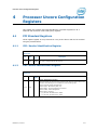
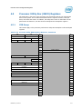
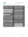
Processor Integrated I/O (IIO) Configuration Registers
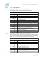
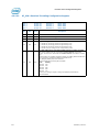
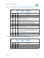
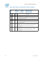
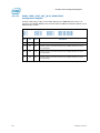
3.2.4.48
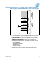
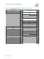
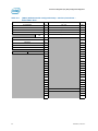
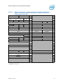
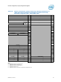
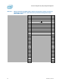
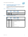
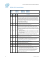
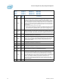
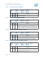
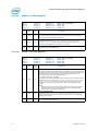
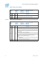
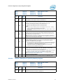
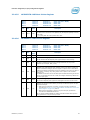
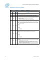
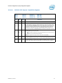
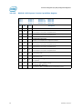
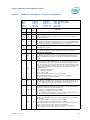
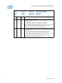
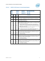
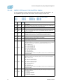
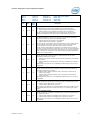
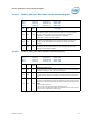
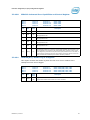
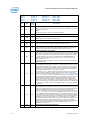
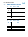
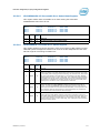
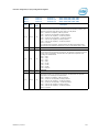
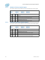
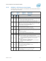
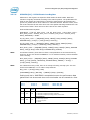
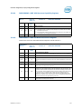
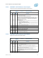
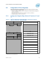
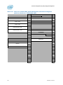
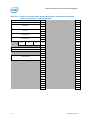
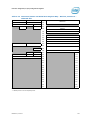
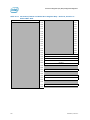
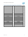
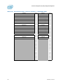
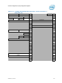
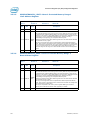
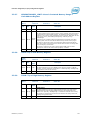
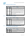
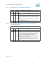
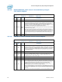
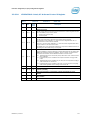
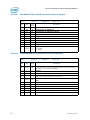
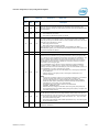
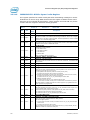
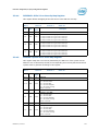
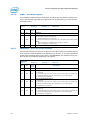
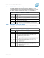
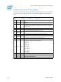
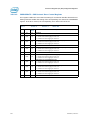
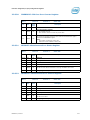
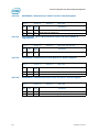
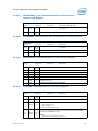
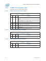
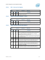
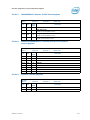
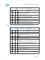
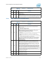
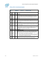
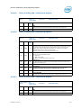
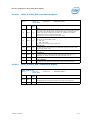
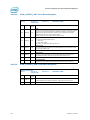
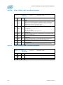
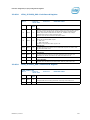
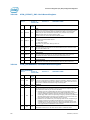
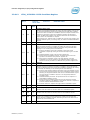
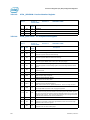
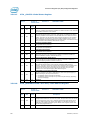
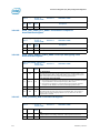
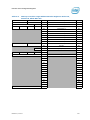
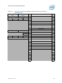
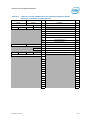
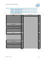
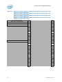
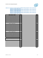
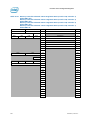
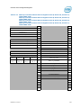
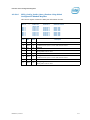
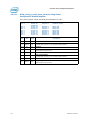
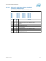
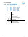
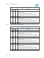
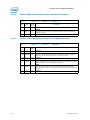
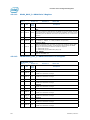
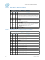
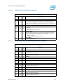
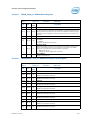
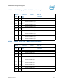
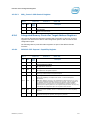
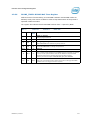
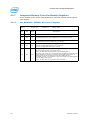
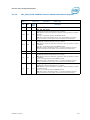
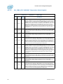
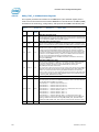
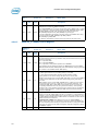
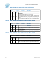
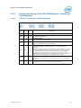
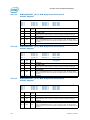
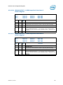
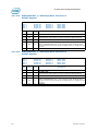
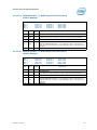
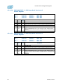
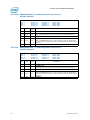
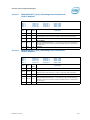
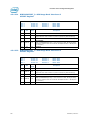
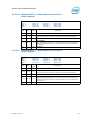
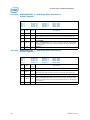
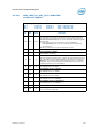
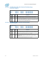
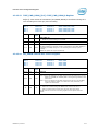
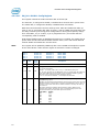
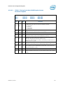
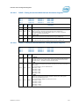
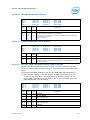
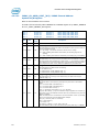
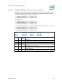
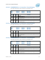
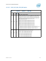
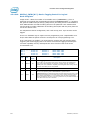
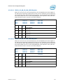
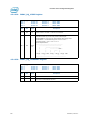
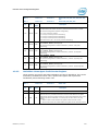
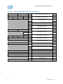
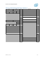
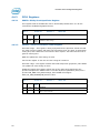
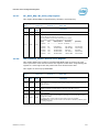
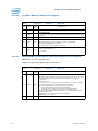
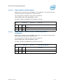
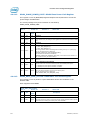
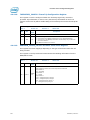
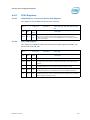
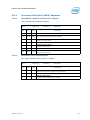
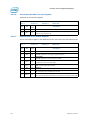
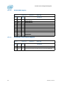
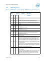
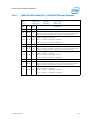
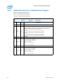
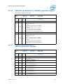
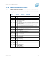
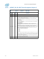
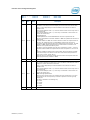
LNKCAP—PCI Express* Link Capabilities Register
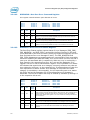
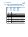
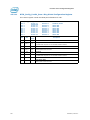
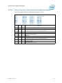
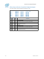
The Link Capabilities register identifies the PCI Express specific link capabilities. The
link capabilities register needs some default values setup by the local host.
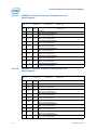
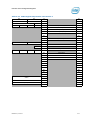
LNKCAP
Bus: 0
Bus: 0
Bus: 0
Bus: 0
0
1
2
3
Function:
Function:
Function:
Function:
0
0–1
0–3
0–3
Offset:
Offset:
Offset:
Offset:
9Ch (PCIe* MODE)
9Ch
9Ch
9Ch
Bit
Attr
Reset
Value
31:24
RW-O
0h
Port Number
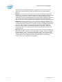
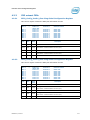
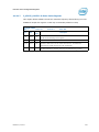
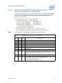
This field indicates the PCI Express port number for the link and is initialized by
software/BIOS. IIO hardware does nothing with this bit.
23:22
RV
0h
Reserved
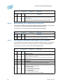
21
RO
1b
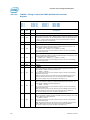
Link Bandwidth Notification Capability
A value of 1b indicates support for the Link Bandwidth Notification status and
interrupt mechanisms.
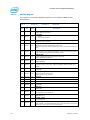
20
RO
1b
Data Link Layer Link Active Reporting Capable
IIO supports reporting status of the data link layer so software knows when it can
enumerate a device on the link or otherwise know the status of the link.
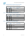
19
RO
1b
Surprise Down Error Reporting Capable
IIO supports reporting a surprise down error condition.
18
RO
0b
Clock Power Management
Does not apply to the processor
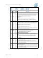
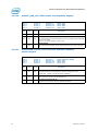
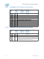
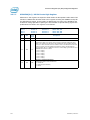
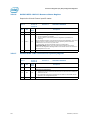
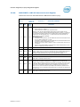
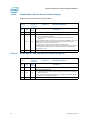
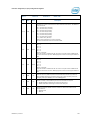
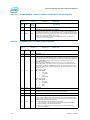
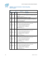
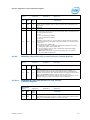
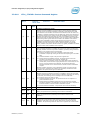
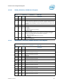
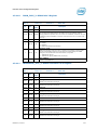
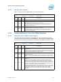
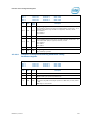
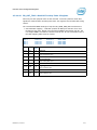
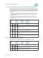
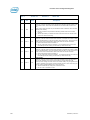
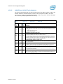
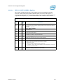
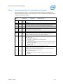
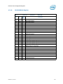
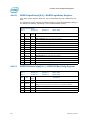
17:15
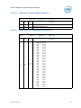
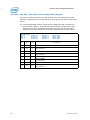
14:12
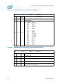
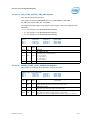
11:10
72
Device:
Device:
Device:
Device:
RW-O
RW-O
RW-O
Description
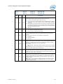
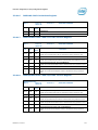
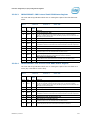
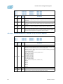
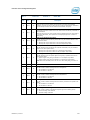
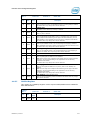
010b
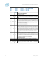
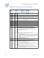
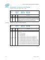
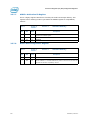
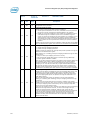
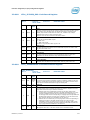
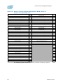
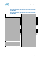
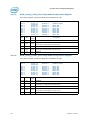
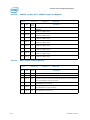
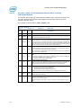
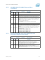
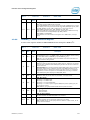
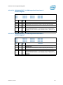
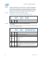
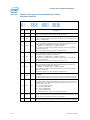
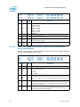
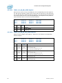
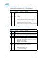
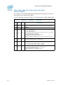
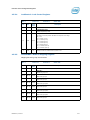
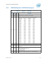
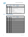
L1 Exit Latency
This field indicates the L1 exit latency for the given PCI Express port. It indicates
the length of time this port requires to complete transition from L1 to L0.
000 = Less than 1 us
001 = 1 us to less than 2 us
010 = 2 us to less than 4 us
011 = 4 us to less than 8 us
100 = 8 us to less than 16 us
101 = 16 us to less than 32 us
110 = 32 us to 64 us
111 = More than 64 us
This register is made writable once by BIOS so that the value is settable based on
experiments post-si.
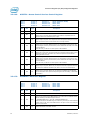
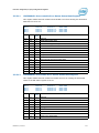
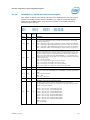
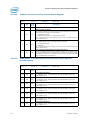
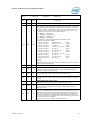
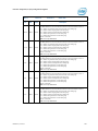
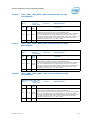
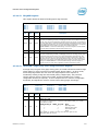
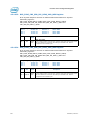
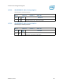
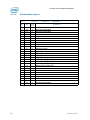
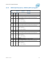
011b
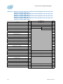
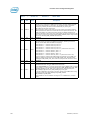
L0s Exit Latency
This field indicates the L0s exit latency (that is, L0s to L0) for the PCI Express
port.
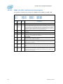
000 = Less than 64 ns
001 = 64 ns to less than 128 ns
010 = 128 ns to less than 256 ns
011 = 256 ns to less than 512 ns
100 = 512 ns to less than 1 us
101 = 1 to less than 2 us
110 = 2 to 4 us
111 = More than 4 us
This register is made writable once by BIOS so that the value is settable based on
experiments post-si.
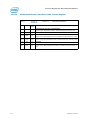
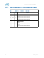
11b
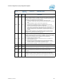
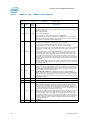
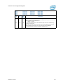
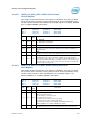
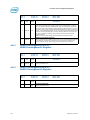
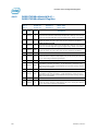
Active State Link PM Support
This field indicates the level of active state power management supported on the
given PCI Express port.
00 = Disabled
01 = L0s Entry Supported
10 = Reserved
11 = L0s and L1 Supported
Datasheet, Volume 2