1
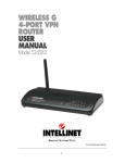
wireless g
4-Port
router
user
manual
Model 524636
INT-524636-UM-0209-02
Contents
1 hardware..................................................................................................................6
1.1 Front Panel / LEDs....................... . ........................................................................6
1.2 Rear Panel / Ports & Jacks.....................................................................................6
1.3 Connecting the Router.................. . ........................................................................7
2 quick installation................... ..............................................................................8
2.1 Time Zone.............................................................................................................10
2.2LAN Settings.........................................................................................................10
2.3 WAN Interface...................................................................................................... 11
2.3.1 Static IP..........................................................................................................12
2.3.2 DHCP Client...................................................................................................12
2.3.3 PPPoE............................................................................................................13
2.3.4 PPTP..............................................................................................................13
2.4 Wireless Basic Settings........................................................................................14
2.5 Wireless Security Settings....................................................................................15
2.5.1 WEP...............................................................................................................16
2.5.2 WPA (TKIP)....................................................................................................17
2.5.3 WPA2 (AES)...................................................................................................18
2.5.4 WPA2 (Mixed)................................................................................................18
3 general setup........................... ............................................................................20
3.1 System..................................................................................................................21
3.1.1 Time Zone Setting............................................................................................21
3.1.2 Password Setup...............................................................................................22
3.1.3 Ping Testing.....................................................................................................22
3.2 WAN.....................................................................................................................23
3.2.1 Static IP..........................................................................................................24
3.2.2 DHCP Client...................................................................................................25
3.2.3 PPPoE (PPP over Ethernet............................................................................26
3.2.4 PPTP..............................................................................................................27
3.2.5 DDNS.............................................................................................................28
3.3LAN......................................................................................................................30
3.4 Wireless................................................................................................................32
3.4.1 Basic Settings.................................................................................................32
3.4.2 Advanced Settings..........................................................................................33
3.4.3 Security..........................................................................................................35
3.4.4 Access Control...............................................................................................36
3.5 Firewall.................................................................................................................37
3.5.1 URL Filtering..................................................................................................37
3.5.2 Port Filtering...................................................................................................38
3.5.3 IP Filtering......................................................................................................39
3.5.4 MAC Filtering..................................................................................................40
3.5.5 Port Forwarding..............................................................................................41
3.5.6 DMZ................................................................................................................42
4 status .............................................. . ......................................................................43
5 tools .............................................. . ......................................................................45
appendix a........................................ . ......................................................................47
appendix b....................................... . ......................................................................50
glossary......................................... . ......................................................................51
specifications............................... . ......................................................................54
2
Thank you for purchasing the INTELLINET NETWORK SOLUTIONS™
Wireless G 4-Port Router, Model 524636.
The Wireless G 4-Port Router lets you experience fast speeds as you
surf the Web, download music or photos, and play online games. This
wireless router works with 802.11g as well as the older 802.11b products,
and also includes a four-port 10/100 LAN switch so you can connect
using network cable or go wireless to satisfy all your needs.
Keeping intruders out of your network can be a challenge, and this
feature-rich wireless router is designed to make that challenge easier.
It includes a true firewall that secures your network against hackers.
With Network Address Translation (NAT) to shield your networked
devices from intruders, plus WEP, WPA and WPA2 encryption to conceal
your information on the wireless LAN from eavesdroppers, you can rest
assured that you’ve taken the necessary precautions to protect the
data on your network.
The easy-to-follow instructions in this user manual help make setup
and operation relatively simple, so you’ll soon be enjoying the benefits
of these additional features:
• Compatible with all common DSL and cable Internet service providers
• Up to 54 Mbps network data transfer rate
• Supports MAC filtering for wireless clients
• Integrated 10/100 Mbps LAN switch with Auto MDI/MDI-X support
• DHCP server assigns IP addresses for all LAN users
• Supports DDNS (dynamic DNS)
• Supports UPNP (Universal Plug and Play)
• Supports virtual server and DMZ (demilitarized zone)
• VPN Pass Through (PPTP, IPSec, L2TP)
• Integrated anti-DoS firewall
• Content control through IP and Port filters
• Remote management function
• Easy installation through Web-based user interface
• Firmware updates via Web-based user interface
• Lifetime Warranty
NOTE: For a quick install procedure, refer to the printed quick install
guide enclosed with this product.
3
safety & compliance statements
FCC Part 15
This equipment has been tested and found to comply with the limits for
a Class B digital device, pursuant to Part 15 of Federal Communications
Commission (FCC) Rules. These limits are designed to provide reasonable
protection against harmful interference in a residential installation. This
equipment generates, uses and can radiate radio frequency energy and,
if not installed and used in accordance with the instructions, may cause
harmful interference to radio communications. However, there is no
guarantee that interference will not occur in a particular installation. If
this equipment does cause harmful interference to radio or television
reception, which can be determined by turning the equipment off and
on, the user is encouraged to try to correct the interference by one or
more of the following measures:
• Reorient or relocate the receiving antenna.
• Increase the separation between the equipment and the receiver.
• Connect the equipment to an outlet on a circuit different from the
receiver.
• Consult the dealer or an experienced radio/TV technician for help.
FCC Caution
This equipment must be installed and operated in accordance with the
provided instructions, and a minimum of 20 cm of spacing must be
provided between the computer-mounted antenna and a person’s body
(excluding extremities of hands, wrist and feet) during wireless modes of
operation.
This device complies with Part 15 of the FCC Rules. Operation is subject
to the following two conditions: (1) this device may not cause harmful
interference, and (2) this device must accept any interference received,
including interference that may cause undesired operation.
Any changes or modifications not expressly approved by the party
responsible for compliance could void the authority to operate equipment.
FCC Radiation Exposure Statement
This equipment complies with FCC radiation exposure limits set forth
4
for an uncontrolled environment. In order to avoid the possibility of
exceeding the FCC radio frequency exposure limits, human proximity
to the antenna shall not be less than 20 cm (8 inches) during normal
operation. The antenna(s) used for this transmitter must not be co-located
or operated in conjunction with any other antenna or transmitter. The
equipment version marketed in the U.S. is restricted to usage of the
channels 1-11 only.
R&TTE Compliance Statement
This equipment complies with all the requirements of Directive 1999/5/
EC of the European Parliament and the Council of March 9, 1999, on
radio equipment and telecommunication terminal equipment and the
mutual recognition of their conformity (R&TTE). The R&TTE directive
repeals and replaces Directive 98/13/EEC (Telecommunications Terminal
Equipment and Satellite Earth Station Equipment) as of April 8, 2000.
Safety
This equipment is designed with the utmost care for the safety of those
who install and use it. However, special attention must be paid to the
dangers of electric shock and static electricity when working with electrical
equipment. All guidelines must, therefore, be followed at all times to
ensure the safe use of the equipment.
EU Countries Intended for Use
The ETSI version of this device is intended for home and office use in
Austria, Belgium, Denmark, Finland, France, Germany, Greece, Ireland,
Italy, Luxembourg, the Netherlands, Portugal, Spain, Sweden and the
United Kingdom. The ETSI version of this device is also authorized for
use in EFTA member states Iceland, Liechtenstein, Norway and
Switzerland.
EU Countries Not Intended for Use
None.
5
1 hardware
1.1 Front Panel / LEDs
The front panel of the Wireless G 4-Port Router features LEDs that
provide an immediate
indication of the device’s
operational status.
LED
Status
Description
PWROn
Off
Power is on.
Power is off.
WLANOn
Flashing
Off
WANOn
Flashing
Off
1/2/3/4On
Flashing
Off
The Wireless LAN has been activated.
There is Wireless LAN activity (transferring or
receiving data).
The Wireless LAN has been deactivated.
The WAN has been connected.
There is WAN activity (transferring or receiving data).
There is no WAN connection.
The LAN has been connected.
There is LAN activity (transferring or receiving data).
There is no LAN connection.
1.2 Rear Panel / Ports & Jacks
The rear panel of the
Wireless G 4-Port
Router features these
ports, buttons and jacks (left to right):
• Four LAN 10/100 Mbps RJ-45 ports for connecting the router to local .
PCs.
• WAN RJ-45 port for connecting the router to a cable, a DSL modem
or the Ethernet.
• Reset button (recessed), which allows you to do two things:
1.If problems occur with your router, press the button with a pencil
tip (for no more than 4 seconds) and the router will re-boot itself,
keeping your original configurations.
6
HARDWARE
2.If problems persist or you forget your password, press the button
for longer than 4 seconds and the router will reset itself to the
factory default settings. NOTE: Your original configurations will be
replaced with the factory default settings.
• Power adapter jack. NOTE: Only use the power adapter included
with the Wireless G 4-Port Router, as a different adapter could result
in product damage.
• Not shown is the 2 dB dipole antenna, which is connected to the rear
panel to the left of the RJ-45 ports.
1.3 Connecting the Router
Before installing the router, connect your PC to the Internet through
your broadband service. (If there is any problem, contact your ISP.)
Then proceed through the following steps.
1. Turn off your PC(s), cable/DSL modem and the router.
2. Adjust the antenna. Normally, upright is a good place to start.
3. Connect the PC(s) and each switch/hub on your local area network
to the LAN ports on the router.
4. Connect the ADSL/DSL/cable modem to the router WAN port.
5. Connect the power adapter between the power socket on the router
and an electrical outlet. The router will start to work automatically.
6. Turn on your PC(s) and the cable/(A)DSL modem.
Shown is a typical setup
for a local area network
(LAN) featuring the
Wireless G 4-Port
Router.
HARDWARE
7
2 quick installation
This Quick Installation section can be used to begin router operation as
quickly as possible, requiring only minimal information in order to use
the router simply as an Internet access device. (A separate printed
Quick Install Guide — presenting the basic hardware configuration and
the Initial Setup below — is packaged with the Wireless G 4-Port
Router.)
First, set up your network; as shown above in Connecting the Router,
for example. Then configure your LAN PC clients so they can obtain
an IP address automatically. By default, the router’s Dynamic Host
Configuration Protocol (DHCP) is activated, meaning that once your
PCs have been configured to obtain an IP address automatically, all
the clients on the network will automatically obtain an IP address, as
well. If needed, refer to Appendix A at the back of this manual for the
Windows 2000, XP and Vista procedures; for other operating systems,
such as Mac and Sun, follow the OS manufacturer’s instructions.
Initial Setup
As stated above, once you have configured your PCs to obtain an IP
address automatically, the router’s DHCP server will automatically
give your LAN clients an IP address. To see if you have obtained an
IP address, see Appendix B at the back of this manual. NOTE: Make
sure that this Wireless G 4-Port Router’s DHCP server is the only
DHCP server available on your LAN. If there is another DHCP on your
network, then you’ll need to switch one of the DHCP servers off. (To
disable the router’s DHCP server, refer to Section 3: General Setup /
LAN Settings.)
Confirmed that the router has provided an IP address? Then continue
with the steps below!
1.Enter the default IP address
192.168.2.1 (the Wireless
G 4-Port Router’s IP
address) into your PC’s
Web browser and press the
Enter key.
8
QUICK INSTALLATION
2.
3.
When the login screen
displays, fill in the “User
Name” and “Password”
fields, then click “OK” to
log in. Note: By default,
the user name is “admin”
and the password is
“1234.” However, for
security reasons it is
recommended that you
change the password as
soon as possible (refer to
Section 3: General Setup / System / Password Setup).
When the Home screen displays (below), click “Quick Setup” to
continue with the Quick Installation procedure. The other three main
sections shown as menu options on the Home screen — General
Setup, Status Information and Tools — are presented and explained
in subsequent sections should you wish to use the many additional
advanced features of the Wireless .G 4-Port Router.
QUICK INSTALLATION
9
2.1 Time Zone
On this screen, you can base the router’s time on these settings, which
will also affect functions such as log entries and firewall settings.
Time Zone Select: Select your local time zone from the drop-down
menu. The router will synchronize time according to your selection.
NTP server: Select the time server to synchronize with.
Click “Next” to proceed to the next screen.
2.2 LAN Settings
On this screen, you can configure the parameters for the local area
network.
10
QUICK INSTALLATION
IP Address: Enter the router’s LAN port IP address (your LAN clients’
default gateway IP address).
Subnet Mask: Specify a subnet mask for your LAN segment.
Click “Next” to proceed to the next screen.
2.3 WAN Interface
On this screen, select one of the four types of connections you’ll be
using — Static IP, DHCP Client, PPPoE or PPTP (as explained in the
subsections below) — to connect your router’s WAN port to your ISP.
Note: Different Internet service providers require different Internet
connection methods. Check with your ISP as to the type of connection
that is required.
WAN Access Type: Select one of the four connection options from
the drop-down menu, then click “Next” to proceed to the screen of
the selected connection type.
Static IP — Your ISP has given you an IP address already.
DHCP Client — Your ISP will automatically give you an IP address.
PPPoE — Your ISP requires you to use a Point-to-Point Protocol
over Ethernet (PPPoE) connection.
PPTP — Your ISP requires you to use a Point-to-Point Tunneling
Protocol (PPTP) connection.
QUICK INSTALLATION
11
2.3.1 Static IP
IP Address: Enter the IP address that your ISP has given you.
Subnet Mask: Enter the ISP-provided subnet mask; e.g.,255.255.255.0.
Default Gateway IP: Enter the ISP’s IP address gateway.
DNS:Enter the ISP’s DNS server IP address.
Click “Next” to proceed to the next screen.
2.3.2 DHCP Client
Hostname: Enter an optional hostname; e.g., “myhome.”
Click “Next” to proceed to the next screen.
12
QUICK INSTALLATION
2.3.3 PPPoE
User Name: Enter the username provided by your ISP.
Password: Enter the password provided by your ISP.
Note: Additional parameters, such as idle timeout, MTU size and
connection type, can be found in General Setup / LAN Setup.
Click “Next” to proceed to the next screen.
2.3.4 PPTP
IP Address: Enter the IP address your ISP has given you to establish
a PPTP connection.
QUICK INSTALLATION
13
Subnet Mask: Enter the ISP-provided subnet mask; e.g.,255.255.255.0.
Server IP Address: Enter the IP address of the ISP gateway.
User Name: Enter the username provided by your ISP for the PPTP
connection (sometimes referred to a the connection ID).
Password: Enter the password provided by your ISP.
Click “Next” to proceed to the next screen.
2.4 Wireless Basic Settings
This screen displays when you click “Next” after configuring any of the
four WAN interfaces above.
Band: This allows you to set the router (acting as an access point) as
802.11b or 802.11g mode. You can also select B+G mode to allow
the AP to select either 802.11b or 802.11g automatically.
SSID:Enter a name for the wireless LAN. All the devices in the same
wireless LAN should have the same ESSID.
Channel Number: Select the channel to be used by the wireless LAN.
All devices in the same wireless LAN should use the same channel.
Enable MAC Clone: Select to allow the router to copy the first seen
MAC address to the WLAN MAC.
Click “Next” to proceed to the next screen.
14
QUICK INSTALLATION
2.5 Wireless Security Settings
Enabling WEP or WPA encryption can prevent unauthorized access to
your wireless network.
Encryption: Select one of the five options from the drop-down menu,
then click “OK” to proceed to the screen of the selected option.
None — Do not apply any encryption to wireless usage: Everyone
has access without needing permission.
WEP — You can select the WEP key length for encryption: 64-bit
or 128-bit. A larger WEP key length will provide a higher level of
security, but the throughput will be lower.
WPA (TKIP) — You can use a pre-shared key to authenticate
wireless stations and encrypt data during communication. Use
TKIP to change the encryption key frequently.
WPA2 (AES) — You can use a pre-shared key to authenticate
wireless stations and encrypt data during communication. Use
CCMP (AES) to change the encryption key frequently.
WPA2 Mixed — This will automatically select TKIP or AES based
on the other communication peer.
QUICK INSTALLATION
15
2.5.1 WEP
When you select either a 64-bit or 128-bit WEP key, you need to enter
WEP keys to encrypt data. You can generate the key by yourself and
enter it; you can also enter four WEP keys and select one of them as
the default key. Then the router can receive any packets encrypted by
one of the four keys.
Key Length: Select the WEP key length for encryption: 64-bit or 128 bit. A larger WEP key length will provide a higher level of security,
but the throughput will be lower.
Key Format: Select ASCII characters (alphanumeric format) or hexa decimal digits (in the “A-F,” “a-f” and “0-9” range) to be the WEP key.
For example, ASCII characters: “guest”; hexadecimal digits:
“12345abcde.”
Default Tx Key: Select one of the four keys as .the default key to
encrypt your data.
Encryption Key 1–4: The WEP keys are used to encrypt data
transmitted in the wireless network. Fill in the fields using the
following guidelines.
• 64-bit WEP: Input 10-digit hex values (in the “A-F,” “a-f” and “0-9”
range) or 5-digit ASCII characters as the encryption keys.
16
QUICK INSTALLATION
• 128-bit WEP: Input 26-digit hex values (in the “A-F,” “a-f” and “0-9”
range) or 13-digit ASCII characters as the encryption keys.
Click “OK” to save and activate all the settings. Now you can use the
router as your Internet gateway.
2.5.2 WPA (TKIP)
Wi-Fi Protected Access (WPA) is an advanced security standard that
lets you use a pre-shared key to authenticate wireless stations and
encrypt data during communication. It uses TKIP to frequently change
the encryption key, making it difficult for hackers to break through and
thus greatly improving security.
Pre-Shared Key Format: Select “Passphrase” (alphanumeric format)
or “Hexadecimal Digits” (in the “A-F,” “a-f” and “0-9” range) for the
pre-shared key. For example, passphrase: “iamguest”; hex digits:
“12345abcde.”
Pre-Shared Key: The pre-shared key is used to authenticate and encrypt
data transmitted in the wireless network. Fill in the fields using the
following guidelines.
• Hex: Input 64-digit hex values (in the “A-F,” “a-f” and “0-9” range)
or at least an 8-character passphrase as the pre-shared keys.
Click “OK” to save and activate all the settings. Now you can use the
router as your Internet gateway.
QUICK INSTALLATION
17
2.5.3 WPA2 (AES)
Wi-Fi Protected Access 2 (WPA2) is an advanced security standard that
lets you use a pre-shared key to authenticate wireless stations and
encrypt data during communication. It uses CCMP (AES) to frequently
change the encryption key, making it difficult for hackers to break
through and thus greatly improving security.
Pre-Shared Key Format: Select “Passphrase” (alphanumeric format)
or “Hexadecimal Digits” (in the “A-F,” “a-f” and “0-9” range) for .the
pre-shared key. For example, passphrase: “iamguest”; hex digits:
“12345abcde.”
Pre-Shared Key: This is used to authenticate and encrypt data
transmitted in the wireless network. Fill in the fields using the
following guidelines.
• Hex: Input 64-digit hex values (in the “A-F,” “a-f” and “0-9” range)
or at least an 8-character passphrase as the pre-shared keys.
Click “OK” to save and activate all the settings. Now you can use the
router as your Internet gateway.
2.5.4 WPA2 Mixed
Wi-Fi Protected Access 2 (WPA2) is an advanced security standard that
lets you use a pre-shared key to authenticate wireless stations and
encrypt data during communication. This option uses TKIP or CCMP
18
QUICK INSTALLATION
(AES) to frequently change the encryption key, making it difficult for
hackers to break through and thus greatly improving security.
Pre-Shared Key Format: Select “Passphrase” (alphanumeric format)
or “Hexadecimal Digits” (in the “A-F,” “a-f” and “0-9” range) for .the
pre-shared key. For example, passphrase: “iamguest”; hex digits:
“12345abcde.”
Pre-Shared Key: This is used to authenticate and encrypt data
transmitted in the wireless network. Enter either a 64-digit hex value
(in the “A-F,” “a-f” and “0-9” range) .or at least an 8-character
passphrase.
Click “OK” to save and activate all the settings. Now you can use the
router as your Internet gateway.
QUICK INSTALLATION
19
3 General setup
Clicking “General Setup” on the Home Page — which displays when
the initial setup is completed (see Quick Installation) — displays the
screen below. If you already configured the Quick Setup Wizard, you
don’t need to configure anything in the General Setup section in order
to start using the Internet. This section does, however, allow you to
configure the router to meet your network’s more specific needs by using
advanced features such as address mapping, access control, hackerattack prevention and DMZ.
To access the various configuration screens, click/select one of the five
subsections listed on the left-hand menu and briefly described below.
System: This section allows you to configure the router’s system time
zone and password, and utilize ping testing.
WAN: This section allows you to select the connection method in order
to establish a connection with your ISP (as in the Quick Installation
section).
LAN: This section allows you to specify the LAN segment’s IP address
and subnet mask, enable/disable DHCP and select an IP range for
the LAN.
Wireless: This section allows you to set up the wireless LAN’s SSID,
WEP key and MAC filtering.
Firewall: This section allows you to configure access control, hacker attack prevention and DMZ.
20
GENERAL SETUP
3.1 System
Select from among Time Zone Setting, Password Setup and Ping Testing
on the left-hand menu to continue with your configuration.
3.1.1 Time Zone Setting
Your router bases its time reference on the settings configured here,
which will affect functions such as log entries and firewall settings.
Current Time: Set the current time.
Time Zone Select: The router will set its time based on this selection.
Enable NTP client update: Check the box to enable the router to
update the time from the NTP server.
NTP server: Select a preset time server or manually input a server IP.
Click “Apply” to save the configurations.
GENERAL SETUP
21
3.1.2 Password Setup
You can change the password required to log in to the router system’s
Web-based management. By default, there is no password, so assign
a password to the administrator as soon as possible and record it in a
safe place. Passwords can contain up to 12 alphanumeric characters
and are case sensitive.
User Name: Change your login username in this field.
New Password: Enter your new password in this field.
Confirmed Password: Enter your new password again for verification.
Note: If you forget your password, you’ll have to reset the router to
the factory default (no password) with the reset button (see Hardware).
Click “Apply” to save the configurations.
3.1.3 Ping Testing
With this tool you can test your Internet connection as well as the status
of a certain host. The example below shows the test results for the
domain “intellinet-network.com.”
22
GENERAL SETUP
If the host or IP address you try to ping is offline or otherwise unavailable,
the response will be “Destination Unreachable,” as shown below.
3.2 WAN
Go to WAN Interface Setup if you’ve already done the Quick Installation
setup and want to change your Internet connection to one of the four
access types below.
GENERAL SETUP
23
Static IP: Your ISP has given you an IP address already.
DHCP Client: Your ISP will automatically give you an IP address.
PPPoE: Your ISP requires a PPPoE connection.
PPTP: Your ISP requires you to use a Point-to-Point Tunneling Protocol
(PPTP) connection.
3.2.1 Static IP
IP Address: Enter the IP address that your ISP has given you.
Subnet Mask: Enter the IP-provided subnet mask (e.g., 255.255.255.0).
Default Gateway: Enter the IP address of ISP’s gateway.
DNS 1: Enter the IP address of the DNS server provided by your ISP.
DNS 2/3: Enter IP addresses of other DNS servers provided by your ISP.
Clone MAC Address: Enterthe MAC address of your computer if your
service provider only permits computers with certain MAC addresses
to access the Internet.
Enable UPnP: By enabling this feature, all client systems that support
Universal Plug and Play can discover this router automatically and
access the Internet through this router without any configuration.
The NAT Traversal function provided by UPnP can let applications
24
GENERAL SETUP
that support UPnP smoothly connect to Internet sites without any
incompatibility problem due to the NAPT port translation.
Enable Web Server Access on WAN Port: Enter where to start the
Web server access on the WAN when you want to access the Web based management from a remote site.
Enable FTP ALG on Port: The FTP Application Layer Gateway is
used to manage the File Transfer Protocol (FTP). FTP uses two
communication channels: one for control commands and one for
the actual files being transferred. When an FTP session is opened,
the FTP client establishes a TCP connection (the control channel),
usually to Port 21 on the FTP server. You can specify the port here.
Enable IPsec/PPTP/L2TP pass through on VPN connection: Check
to select these options if you need to create VPN connections to a
remote location, such as your office. If you’re not sure which of the
protocols you need, you may activate all three.
Click “Apply” to save the configurations.
3.2.2 DHCP Client
This is similar to the DHCP Client screen in Quick Installation, but some
ISPs may require additional information beyond the hostname.
GENERAL SETUP
25
Host Name: Enter the hostname of your computer. NOTE: This is
optional, required only if your service provider asks you to do so.
Obtain DNS Automatically: Select if your ISP requires you to obtain
a DNS via the DHCP server before you connect to the Internet.
Set DNS Manually: Select if your ISP gives you a static DNS server
for connecting to the Internet.
DNS 1: Enter the IP address of the DNS server provided by your ISP.
DNS 2/3: Enter IP addresses of other DNS servers provided by your ISP.
Clone MAC Address: Enter the MAC address of your computer if your
service provider only permits computers with certain MAC addresses
to access the Internet.
NOTE: The remaining features/options are identical to those in the
Static IP section above.
Click “Apply” to save the configurations.
3.2.3 PPPoE (PPP over Ethernet)
User Name: Enter the username assigned by your ISP.
Password: Enter the password assigned by your ISP.
Service Name: Enter e a name for this Internet service (optional).
Connection Type: Select one of three Internet connection types:
• Continuous — Keeps an Internet connection alive (no disconnect).
• Connect on Demand — Only connects to the Internet when a
connect attempt is made.
26
GENERAL SETUP
• Manual — Only connects to the Internet when “Connect” is
clicked; disconnects when “Disconnect” is .clicked.
Idle Time: Specify the amount of Internet-inactivity time that needs to
elapse before shutting down. NOTE: This option is only available
when “Connect on Demand” is selected.
MTU Size: Enter the MTU value of your network connection. If unknown,
you can use the default value.
Obtain DNS Automatically: Select if your ISP requires you to obtain
a DNS via the DHCP server before you connect to the Internet.
Set DNS Manually: Select if your ISP gives you a static DNS server
for connecting to the Internet.
DNS 1: Enter the IP address of the DNS server provided by your ISP.
DNS 2/3: Enter IP addresses of other DNS servers provided by your ISP.
Clone MAC Address: Enter the MAC address of your computer if your
service provider only permits computers with certain MAC addresses
to access the Internet.
NOTE: The remaining features/options are identical to those in the
Static IP section above.
Click “Apply” to save the configurations.
3.2.4 PPTP
GENERAL SETUP
27
IP Address: Enter the IP address that your ISP has given you.
Subnet Mask: Enter the IP-provided subnet mask (e.g., 255.255.255.0).
Server IP Address: Enter the IP address of the PPTP gateway assigned
by your ISP.
User Name: Enter the username assigned by your ISP.
Password: Enter the password assigned by your ISP.
MTU Size: Enter the MTU value of your network connection. If unknown,
you can use the default value.
Obtain DNS Automatically: Select if your ISP requires you to obtain
a DNS via the DHCP server before you connect to the Internet.
Set DNS Manually: Select if your ISP gives you a static DNS server
for connecting to the Internet.
DNS 1: Enter the IP address of the DNS server provided by your ISP.
DNS 2/3: Enter IP addresses of other DNS servers provided by your ISP.
Clone MAC Address: Enter the MAC address of your computer if your
service provider only permits computers with certain MAC addresses
to access the Internet.
NOTE: The remaining features/options are identical to those in the
Static IP section above.
Click “Apply” to save the configurations.
3.2.5 DDNS
DDNS (Dynamic Domain Name System) allows you to map the static
domain name to a dynamic IP address. You need to obtain an account,
password and your static domain name from the DDNS service provider.
This Wireless G 4-Port Router supports DynDNS.org and TZO.
Enable DDNS: Check/select to enable/disable the router’s DDNS
function. NOTE: The default setting is “Disabled.”
Service Provider: Select a DDNS service provider.
Domain Name: Enter your static domain name for use with DDNS.
User Name/Email: Enter the account identification your DDNS service
provider assigned to you.
Password/Key: Enter the password you set for the DDNS service
account above.
Click “Apply” to save the configurations.
28
GENERAL SETUP
How to Use dyndns.org
The same username and password required to log in to the dyndns.org
Web site to manage your accounts (above) need to be entered for the
DDNS configuration of the router (below).
GENERAL SETUP
29
Check that the hostname in your dyndns.org account (above) is the
same as the hostname entered into the router’s DDNS configuration
(below). If it is, click “Apply” to save the settings.
3.3 LAN
This screen allows you to specify a private IP address for your router’s
LAN ports, as well as a subnet mask for your LAN segment.
30
GENERAL SETUP
IP Address: This is the router’s LAN port IP address (your LAN clients’
default gateway IP address). The default is 192.168.2.1.
Subnet Mask: Specify a subnet mask for your LAN segment. The
default is 255.255.255.0.
Default Gateway: Specify the default gateway for your LAN segment.
DHCP: Select the DHCP type for your LAN segment.
• Server — This is the default setting. The router will automatically
give your LAN clients an IP address.
• Client — The router will get an IP address from the LAN DHCP
server automatically. If the DHCP server is not enabled, you’ll
need to manually set your LAN clients’ IP addresses. If you want
the router to be your LAN client’s default gateway, make sure that
LAN Client is in the same subnet as this router.
DHCP Client Range: Enter an IP address range for your DHCP server
to issue IP addresses to your LAN clients. Note: By default, this
IP range is from 192.168.2.100 to 192.168.2.199. If you want your
PC to have a static/fixed IP address, you’ll need to choose an IP
address outside this IP address pool, or range.
Show Client: Click to display a list of connected computers that have
obtained an IP
address from the
router’s DHCP
server. NOTE:
Computers with a
static IP address
setup aren’t shown.
Click “Refresh” on
this sub-screen to update the information.
802.1d Spanning Tree: If this function is enabled, this router will use
the Spanning Tree protocol to prevent a network loop from occurring
in the LAN ports. The default is “Disabled.”
Clone MAC Address: Specify the MAC address for your LAN interface.
Click “Apply” to save the configurations.
GENERAL SETUP
31
3.4 Wireless
This section allows you to build a wireless LAN so that all PCs equipped
with an IEEE 802.11b or 801.11g wireless network adapter can connect
to your intranet.
It supports
WEP, WPA
and WPA2
encryption to
enhance the
security of
your wireless
network.
3.4.1 Basic Settings
Disable Wireless LAN Interface: Check/select this box to disable the
wireless function.
Band: Select “802.11b” or “802.11g.” You also can select the B+G mode
to allow the router to select either the 802.11b or 802.11g connection
automatically.
SSID: Enter the name of the wireless LAN. All devices in the same
32
GENERAL SETUP
wireless LAN should have the same ESSID. The default entry is
“INTELLINET.”
Channel Number: Select a wireless LAN channel. All devices in the
same wireless LAN should use the same channel. The default is 11.
Associated Clients: Click “Show Active Clients” to display the Active
Wireless Client table, which shows the status of all active wireless
stations that are connecting to the router (as an access point).
Click “Apply” to save the configurations.
3.4.2 Advanced Settings
You can set advanced wireless LAN parameters in this section; however,
changes aren’t recommended unless you know what effect the changes
will have on this router.
Authentication Type: There are three authentication options:
• Open System — This allows wireless stations to associate with
the router without WEP encryption.
GENERAL SETUP
33
• Shared Key — With this option, you should also set up the WEP
key on the Encryption screen, and wireless stations should use
WEP encryption in the authentication phase to associate with the
router.
• Auto — This allows wireless clients to associate with the router
by using either of the two authentication types.
Fragment Threshold: Enter the maximum packet size during the
fragmentation of data to be transmitted. NOTE: If you set this value
too low, it will result in poor performance.
RTS Threshold: When the packet size is smaller than the RTS threshold,
the wireless router will not use the RTS/CTS mechanism to send
this packet.
Beacon Interval: Enter a time interval for the router’s beacon broadcast.
The beacon is used to synchronize the wireless network.
Data Rate: This is the rate the router (as an access point) transmits
data packets. The AP will use the highest possible selected rate.
Preamble Type: “Long Preamble” can provide better wireless LAN
compatibility; “Short Preamble” can provide better performance.
Broadcast SSID: When this function is enabled, every wireless station
located within range can discover this access point. (If you’re building
a public wireless network, enabling this feature is recommended.)
Disabling, however, can provide better security.
IAPP: Enabling this function allows wireless stations to roam between
IAPP-enabled access points within the same wireless LAN.
802.11g Protection: Enabling this function (also called CTS Protection)
is recommended to activate the protection mechanism, which can
decrease the rate of data collision between 802.11b and 802.11g
wireless stations. When the protection mode is enabled, the AP’s
throughput will be a bit lower due to more transmitted frame traffic.
WMM: Enabling Wi-Fi MultiMedia (which is recommended) will enhance
the data transfer performance of multimedia content when it’s being
transferred over the wireless network.
RF Output Power: You’ll want to use maximum power (100%) most of
the time, but there may be instances when the distance between
the wireless client and the router is very short and a lower power
output is enough to create a fast and stable connection. In those
instances, reducing the power output can help keep unauthorized
users from breaking in to your wireless network.
34
GENERAL SETUP
Turbo Mode: This enhances the data transfer rate of a WLAN (up to
35 Mbps). The default setting, “Auto,” is recommended.
Click “Apply” to save the configurations.
3.4.3 Security
As an access point, the Wireless G 4-Port Router provides complete
wireless LAN security functions — WEP, IEEE 802.11x, IEEE 802.11x
with WEP, WPA with pre-shared key and WPA with RADIUS — which
protect your wireless LAN from illegal access. Make sure your wireless
stations enable the same security function.
Encryption: Mode options are “None,” “WEP,” “WPA,” “WPA2” and
“WPA2 mixed.” If WEP encryption is selected in the drop-down menu,
click “Set WEP Key” and select either “WEP 64 bits” (which is the
default setting) or “WEP 128 bits.” .The larger key length provides a
higher level of security, but the throughput will be lower.
Use 802.1x Authentication: IEEE 802.1x is an authentication protocol.
Every user must use a valid account to log in to this access point
GENERAL SETUP
35
before accessing the WLAN. Authentication is processed by a RADIUS
server. Check this box to authenticate users by IEEE 802.1x.
WPA Authentication Mode: WPA can authenticate by enabling either
“RADIUS” or “Pre-Shared Key.”
WPA / WPA2 Cipher Suite: Select either “TKIP” or “AES” as the WPA /
WPA2 key exchange method.
Pre-Shared Key Format: Select “Passphrase” (alphanumeric format)
or “Hexadecimal Digits” (in the “A-F,” “a-f” and “0-9” range) for .the
pre-shared key. For example, passphrase: “iamguest”; hex digits:
“12345abcde.”
Pre-Shared Key: This is used to authenticate and encrypt data
transmitted in the wireless network. Enter either a 64-digit hex value
(in the “A-F,” “a-f” and “0-9” range) .or at least an 8-character
passphrase.
Authentication Radius Server: Fill in the fields for the port, IP address
and password to be used for the external RADIUS server.
Click “Apply” to save the configurations.
3.4.4 Access Control
This screen allows you to control MAC addresses to prevent unauthorized
access to your wireless network.
36
GENERAL SETUP
Wireless Access Control Mode: Enable or disable this function.
MAC Address / Comment: Fill in these two fields for the wireless station
to be added to the access list, then click “Apply.” Once one or more
MAC addresses are given access to the network, the resulting list
will display at the bottom of the screen. To remove an address from
the list (thus denying access), highlight it and click “Delete Selected”
(or “Delete All” if you’ve highlighted more than one). To clear all of
your current selections, click “Reset.”
3.5 Firewall
The Wireless G 4-Port Router provides extensive firewall protection by
restricting connection parameters, thus limiting the risk of a hacker
attack and defending against a wide array of common Internet attacks.
NOTE: Some programs, such as Internet phones and network games
or file-sharing
programs, need
more than one
connection, but
because of the
firewall may not
work correctly
unless you go
to the Special
Applications
subsection and
follow the steps that make those programs compatible with the router.
3.5.1 URL Filtering
With URL filtering, you can
block access to any Web site
or Web page that contains a
blacklisted keyword, ideal for
limiting children’s exposure
to unsuitable Web content.
Enable URL Filtering: Select to activate the function.
URL Address: Enter the keyword or part of the URL in the text field,
then click “Apply” to add the keyword to the setup.
GENERAL SETUP
37
Once one or more items
are listed, the resulting
Current Filter Table list
can be displayed. Delete
individual listings in the
URL Address column by
checking the corresponding
box in the Select column and then clicking “Delete Selected.” Delete all
items on the list at once by clicking “Delete All.” To clear all of your
current selections, click “Reset.”
Examples of Filters and Effects
www.intellinet-network.com: Access to the Web site www.intellinet network.com will be blocked, but access to intellinet-network.com
is still allowed (note the missing “www”).
intellinet-network.com: Access to both www.intellinet-network.com
and intellinet-network.com is blocked.
network: Access is blocked to any Web site that contains the keyword
“network,” such as intellinet-network.com, networkipcamera.com or
networksolutions.com. Furthermore, this prevents you from searching
for the keyword “network” using a search engine; e.g., Google.
ads: This filter can help reduce the amount of advertisements shown
on Web pages. It will prevent any content that resides in a location
(www.domain.com/images/ads/, as an example) from loading.
3.5.2 Port Filtering
This section allows you to prevent users from accessing certain Internet
applications/services (e.g., Web sites, e-mail, FTP sites) by restricting
the flow of certain types of data packets. (Also see IP Filtering below.)
Enable Port Filtering: Select to activate the function.
Port Range / Protocol / Comment: For any item you want to include
in your port-filtering efforts, enter a port range, select one of the
protocols from the drop-down menu, add any comments that can
help identify the item whenever you refer to the list, then click “Apply.”
Once one or more items are listed, the resulting Current Filter Table
list will display at the bottom of the screen. To remove an item from
38
GENERAL SETUP
the list, highlight it and click “Delete Selected” .(or “Delete All” if
you’ve highlighted more than one). To clear all current selections,
click “Reset.” To clear all current text fields, click “Cancel.”
3.5.3 IP Filtering
This section allows you to prevent users from accessing certain Internet
applications/services (e.g., Web sites, e-mail, FTP sites) by restricting
the flow of certain types of data packets. (See Port Filtering above.)
GENERAL SETUP
39
Enable IP Filtering: Select to activate the function.
Local IP Address / Protocol / Comment: For any item to which you
want to apply the IP filtering rules, enter a local IP address, select
one of the protocols from the drop-down menu, add any comments
that can help identify the item whenever you refer to the list, then
click “Apply.” Once one or more filters are applied, the resulting
Current Filter Table list will display at the bottom of the screen. To
remove an item from the list, highlight it and click “Delete Selected”
(or “Delete All” if you’ve highlighted more than one). To clear all
current selections, click “Reset.” To clear all current text fields, click
“Cancel.”
3.5.4 MAC Filtering
This section allows you to prevent users from accessing certain Internet
applications/services (e.g., Web sites, e-mail, FTP sites) by restricting
the flow of certain types of data packets. (See Port / IP Filtering above.)
Enable MAC Filtering: Select to activate the function.
MAC Address / Comment: For any item you want to to which you want
to apply the MAC filtering rules, enter a MAC address, add any
comments that can help identify the item whenever you refer to the
list, then click “Apply.” Once one or more items are listed, the resulting
Current Filter Table list will display at the bottom of the screen. To
40
GENERAL SETUP
remove an item from the list, highlight it and click “Delete Selected”
(or “Delete All” if you’ve highlighted more than one). To clear all
current selections, click “Reset.” To clear all current text fields, click
“Cancel.”
3.5.5 Port Forwarding
This section allows you to re-direct a particular range of service port
numbers (from the Internet / WAN ports) to a particular LAN IP address.
This helps you host some servers behind the router’s NAT firewall.
Enable Port Forwarding: Select to activate the function.
IP Address: Enter the private IP address of the server behind the NAT
firewall. Note: You need to give your LAN PC clients a fixed/static
IP address for Port Forwarding to work properly.
Protocol: Select the protocol type to be forwarded: “TCP” or “UDP,” or
both.
Port Range: Enter the range of ports to be forwarded to the private IP.
Comment: Enter a description of the item being filtered, then click “Apply.”
Once one or more items are listed, the resulting Current Port
Forwarding Table list will display at the bottom of the screen. To
remove an item from the list, highlight it and click “Delete Selected”
(or “Delete All” if you’ve highlighted more than one). To clear all
current selections, click “Reset.” To clear all current text fields, click
“Cancel.”
GENERAL SETUP
41
3.5.6 DMZ
If you have a local client PC that can’t run an Internet application properly
from behind the NAT firewall (games, for example), then you can open
the client up to unrestricted two-way Internet access by defining a DMZ
host. The DMZ function allows you to re-direct all packets going to your
WAN port IP address to a particular IP address in your LAN.
Enable DMZ: Select to activate the function.
DMZ Host IP Address: Enter the IP address of a particular host in your
LAN that will receive all the packets originally going to the WAN
port / public IP address above. Note: You need to give your LAN
PC clients a fixed/static IP address for DMZ to work properly.
You can now configure other advanced sections or start using the
router with the advanced settings in place.
42
GENERAL SETUP
4 status
The Status section allows
you to monitor and reference
such things as the connection
status of the router’s WAN/
LAN interfaces, the current
firmware version numbers
and any illegal attempts to
access your network. In
addition, it contains the
system log and the statistics
screen.
4.1 System Log
This screen displays any event occurring after system startup.
STATUS
43
Enable Log: Select to activate the function, then select either “wireless
only” or “system all.”
Enable Remote Log / Log Server IP Address: Select to send all log
information to a remote server, and enter the server IP address in
the text field.
Click “Refresh” to view the most recent informatino; click “Clear” to
remove current data. When the system is powered down, the system
log will disappear if not saved to a local file.
4.2 Statistics
This screen displays pertinent information about WAN, LAN and WLAN
packet transmissions.
44
STATUS
5 tools
This section allows you to save or restore configuration settings and
upgrade system firmware.
5.1 Save/Reload Settings
This screen allows you to save (back up) the router’s current configuration
settings, which, of course, provides added protection and convenience
should problems occur with the router and you have to reset to factory
defaults.
Save Settings to File: Click “Save” to place the current configuration
in the “config.bin” file on your PC.
Load Settings from File: Click “Browse” to locate the previously saved
configuration file; then click “Upload” to restore the configuration.
Reset Settings to Default: Click “Reset” to force the router to perform
a power reset and restore the original factory settings (as they were
when you first purchased the router).
tools
45
5.2 Upgrade Firmware
This screen allows you to upgrade the Wireless G 4-Port Router’s
system firmware. To do so, you need to download the firmware file to
your local hard drive.
Select File: Enter the filename of the firmware already downloaded to
the hard drive field, or click “Browse” to locate the file. Click “Upgrade”
to begin the firmware upgrade (which may take a few minutes).
NOTE: Be careful that you don’t turn off the router during the firmware
upload, as this can crash the system. Once the upgrade is complete,
you can start using the router again.
46
TOOLS
appendix a
This section presents the basic steps for using Windows 2000, XP or
Vista to obtain an IP address automatically, as directed in the Quick
Installation section.
Windows 2000
1. Go to Start → Settings → Control Panel.
2.Double-click on the Network and Dial-up Connections icon. In the
Network and Dial-up Connection window, double-click on the Local
Area Connection icon.
3. In the Local Area Connection window, click “Properties.”
4. Check your list of Network Components. You should see “Internet
Protocol [TCP/IP]” on your list. Select it and click “Properties.”
5. In the Internet Protocol (TCP/IP) Properties window, select “Obtain
an IP address automatically” and “Obtain DNS server address
automatically.”
6. Click “OK” to
confirm the
setting. Your PC
will now obtain
an IP address
automatically from
your router’s
DHCP server.
Note: Make sure
that the Wireless G
4-Port Router’s
DHCP server is the
only DHCP server
available on your LAN.
appendix a
47
Windows XP
1. Go to Start → Settings, then click “Network Connections.”
2.Double-click on the Local Area Connection icon.
3. Check your list of Network Components. You should see “Internet
Protocol [TCP/IP]” on your list. Select it and click “Properties.”
4. In the Internet Protocol (TCP/IP) Properties window, select “Obtain .
an IP address
automatically”
and “Obtain DNS
server address
automatically.”
5. Click “OK” to
confirm the
setting. Your PC
will now obtain
an IP address
automatically
from your router’s
DHCP server.
Note: Make sure
that the Wireless G
4-Port Router’s
DHCP server is the
only DHCP server
available on your
LAN.
48
appendix a
Windows Vista
1. Go to Start → Settings → Control Panel.
2.Double-click Network and Sharing Center.
3. Click “Manage network connections”; right-click on the Local Area
Connection icon; then select “Properties.”
4. Check your list of Network Components. You should see “Internet
Protocol Version 4 (TCP/IPv4)” on your list. Select it and click
“Properties.”
5. In the Internet
Protocol Version
4 (TCP/IPv4)
Properties
window, select
“Obtain an IP
address
automatically”
and “Obtain
DNS server
address
automatically.”
6. Click “OK” to
confirm the
setting. Your PC
will now obtain
an IP address
automatically
from your
router’s DHCP
server.
Note: Make sure that the Wireless G 4-Port Router’s DHCP server is
the only DHCP server available on your LAN.
appendix a
49
appendix B
To manually find your PC’s IP and MAC addresses in Windows, open the
Command Prompt program, type “Ipconfig /all” and press the Enter key.
Your PC’s IP address is listed as “IP address (192.168.1.77).”
The router’s IP address is listed as “Default Gateway (192.168.1.254).”
Your PC’s MAC address is listed as “Physical Address (00-50-FC-FE-02-DB).”
50
appendix b
glossary
Default Gateway: Every non-router IP device needs to configure a
default gateway’s IP address. When the device sends out an IP
packet, if the destination is not on the same network the device has
to send the packet to its default gateway, which will then send it out
toward the destination.
DHCP: The Dynamic Host Configuration Protocol automatically gives
every computer on your home network an IP address.
DNS Server IP Address: The Domain Name System allows Internet
servers to have a domain name (such as www.Broadbandrouter.com)
and one or more IP addresses (such as 192.34.45.8). A DNS server
keeps a database of Internet servers and their respective domain
names and IP addresses, so that when a domain name is requested
(as when typing “Broadbandrouter.com” into your Internet browser)
the user is sent to the proper IP address. The DNS server IP address
used by the computers on your home network is the location of the
DNS server your ISP has assigned to you.
DSL Modem: A Digital Subscriber Line modem uses existing phone
lines to transmit data at high speeds.
Ethernet: A standard for computer networks. Ethernet networks are
connected by special cables and hubs, and move data around at up
to 10/100 million bits per second (Mbps).
Idle Timeout: Idle Timeout is designed so that after there is no traffic
to the Internet for a pre-configured amount of time, the connection
will automatically be disconnected.
IP Address and Network (Subnet) Mask: An Internet Protocol address
consists of a series of four numbers — separated by periods — that
identifies a single, unique Internet computer host in an IP network.
As an example, 192.168.2.1 consists of two sections: the IP network
address and the host identifier. The IP address is a 32-bit binary
pattern that can be represented as four cascaded decimal numbers
separated by periods: aaa.aaa.aaa.aaa, where each “aaa” can be
anything from 000 to 255; or as four cascaded binary numbers
separated by periods: bbbbbbbb.bbbbbbbb.bbbbbbbb.bbbbbbbb,
where each “b” can either be 0 or 1.
A network mask is also a 32-bit binary pattern, and consists of
glossary
51
consecutive leading 1’s followed by consecutive trailing 0’s, such as
11111111.11111111.11111111.00000000. Therefore, a network mask
can sometimes be described simply as “x” number of leading 1’s.
When both are represented side by side in their binary forms, all
bits in the IP address that correspond to 1’s in the network mask
become part of the IP network address, and the remaining bits
correspond to the host ID. For example, if the IP address for a device
is, in its binary form, 11011001.10110000.10010000.00000111, and
if its network mask is 11111111.11111111.11110000.00000000, then
its network address is 11011001.10110000.10010000.00000000 and
its host ID is 00000000.00000000.00000000.00000111. This is a
convenient and efficient method for routers to route IP packets to
their destination.
ISP Gateway Address: This is an IP address for the Internet router
located at the ISP’s office.
ISP: An Internet Service Provider is a business that provides connectivity
to the Internet for individuals, businesses or organizations.
LAN: A Local Area Network is a group of computers and devices
connected together in a relatively small area,such as a house or
office. Your home network is considered a LAN.
MAC Address: A Media Access Control address is the hardware
address of a device connected to a network. The MAC address is a
unique identifier for a device with an Ethernet interface. It’s composed
of two parts: 3 bytes of data corresponding to the manufacturer .ID
(unique for each manufacturer), plus 3 bytes often used as the
product’s serial number.
NAT: Network Address Translation is a process that allows all of the
computers on your home network to use one IP address. Using the
router’s NAT capability, you can access the Internet from any computer
on your home network without having to purchase more IP addresses
from your ISP.
Port: Network clients (LAN PC) uses port numbers to distinguish one
network application/protocol from another. Below is a list of common
applications and protocol/port numbers:
52
glossary
Application
Telnet
FTP
SMTP
POP3
H.323
SNMP
SNMP Trap
HTTP
PPTP
PC Anywhere
PC Anywhere
Protocol
TCP
TCP
TCP
TCP
TCP
UCP
UDP
TCP
TCP
TCP
UDP
Port Number
23
21
25
110
1720
161
162
80
1723
5631
5632
PPPoE: Point-to-Point Protocol over Ethernet, a communications protocol
for transmitting data over the Ethernet among different manufacturers,
is a secure data transmission method originally created for dial-up
connections (PPPoE is for Ethernet connections). PPPoE relies on two
widely accepted standards: Ethernet and the Point-to-Point Protocol.
Protocol: A protocol is a set of rules for interaction agreed upon by
multiple parties so that when they interface with each other based on
such a protocol, the interpretation of their behavior is well defined
and can be made objectively, without confusion or misunderstanding.
Router: A router is an intelligent network device that forwards packets
between different networks based on network layer address
information such as IP addresses.
Subnet Mask: A subnet mask, which may be a part of the TCP/IP
information provided by your ISP, is a set of four numbers (e.g.,
255.255.255.0) configured like an IP address. It is used to create IP
address numbers used only within a particular network (as opposed
to valid IP address numbers recognized by the Internet, which must
be assigned by InterNIC).
TCP/IP, UDP: Transmission Control Protocol/Internet Protocol and
Unreliable Datagram Protocol. TCP/IP is the standard protocol for
data transmission over the Internet. Both TCP and UDP are transport
layer protocols. TCP performs proper error detection and error
recovery, and thus is reliable. UDP, on the other hand, is not reliable.
Both run on top of the IP (Internet Protocol), a network layer protocol.
WAN: A Wide Area Network connects computers in separate areas
(e.g., different buildings, cities, countries). The Internet is a WAN.
Web-based Management Graphical User Interface (GUI): Many
devices support a graphical user interface that is based on the Web
browser. This means the user can use the familiar Netscape or MS
Internet Explorer to control or monitor the device being managed.
glossary
53
specifications
Standards
•IEEE 802.1d (Spanning Tree
Protocol)
• IEEE 802.1x (Wireless User
Authentication)
• IEEE 802.11b (11 Mbps Wireless
LAN)
• IEEE 802.11g (54 Mbps Wireless
LAN)
• IEEE 802.3 (10Base-T Ethernet)
• IEEE 802.3u (100Base-TX Fast
Ethernet)
translation)
- DHCP
- DNS
• NAT:
- Port forwarding
• Firewall:
- Port filter
- IP filter
- Access control based on MAC
address
- DMZ (demilitarized zone)
• Supports UPNP (Universal Plug
and Play)
General
• Supports DHCP (client/server)
• LAN ports: 4 RJ45 10/100 Mbps • Supports PPPoE (DSL), DHCP
data ports
(cable) and static IP
• LAN ports with Auto MDI/MDI-X • Supports VPN PPTP, L2TP and
• Certifications: FCC Class B, CE IPsec pass-through
Mark, RoHS
Wireless
Router
• Chipset: RTL8225
• Chipset: Realtek RTL8186
• Wireless frequency range:
• Supported WAN connection types: 2.412 - 2.484 GHz
-Dynamic IP (DHCP for cable
• Modulation technologies:
service)
- 802.11b: Direct Sequence
- Static IP
Spread Spectrum (DSSS):
- PPPoE (for DSL)
DBPSK, DQPSK, CCK
• Protocols:
- 802.11g: Orthogonal Frequency
- CSMA/CA
Division Multiplexing (OFDM):
- CSMA/CD
BPSK, QPSK, 16QAM, 64QAM
- TCP/IP
• Number of channels: 11
- UDP
• Data rates:
- ICMP
- IEEE 802.11b (11 Mbps, 5.5
- PPPoE
Mbps, 2 Mbps, 1 Mbps)
- NTP
- IEEE 802.11g (54 Mbps, 48
- NAT (network address
Mbps, 36 Mbps, 24 Mbps, 18
54
specifications
Mbps, 12 Mbps, 9 Mbps, 6 Mbps)
• Output power:
- OFDM: 15 dBm +/- 1 dBm (54
Mbps, 50 mW max.)
- CCK: 17 dBm +/- 1 dBm (11
Mbps, 50 mW max.)
• Maximum coverage distance:
100 m / 300 ft. (indoor),
300 m / 900 ft. (outdoor)
• Wireless security:
- WEP encryption (64-/128-bit)
- WPA (TKIP and AES)
- WPA2 (TKIP and AES)
- Client access control through
media access control (MAC)
filter
• Antenna: single dipole antenna,
2 dBi gain
Power
• External power adapter:
12 V DC, 1.0 A
• Power consumption:
5.5 Watts max.
Package Contents
• Wireless G 4-Port Router
• User manual
• Power adapter
• Ethernet Cat5 RJ45 cable,
1.0 m (3 ft.)
LEDs
• Power
• WLAN Link/Act
• WAN Link/Act
• LAN 1-4 Link/Act
Environmental
• Dimensions: 157 (W) x 127 (L) x
30 (H) mm (6.2 x 5.0 x 1.2 in.)
• Weight: 0.8 kg (1.7 lbs.)
• Operating temperature: 0 – 40°C
(32 – 104°F)
• Operating humidity: 10 – 90%
RH, non-condensing
• Storage temperature: -20 – 60°C
(4 – 149°F)
specifications
55
INTELLINET NETWORK SOLUTIONS™ offers a complete line
of active and passive networking products.
Ask your local computer dealer for more information or visit
www.intellinet-network.com.
Copyright © INTELLINET NETWORK SOLUTIONS
All products mentioned are trademarks or registered trademarks of their respective owners.