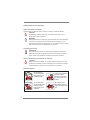
1
CoreHT Series
User Manual
Version 1.0
Published April 2011
Copyright©2011 ASRock INC. All rights reserved.
1
Copyright Notice:
No part of this manual may be reproduced, transcribed, transmitted, or translated in
any language, in any form or by any means, except duplication of documentation by
the purchaser for backup purpose, without written consent of ASRock Inc.
Products and corporate names appearing in this manual may or may not be registered trademarks or copyrights of their respective companies, and are used only for
identification or explanation and to the owners’ benefit, without intent to infringe.
Disclaimer:
Specifications and information contained in this manual are furnished for informational use only and subject to change without notice, and should not be constructed
as a commitment by ASRock. ASRock assumes no responsibility for any errors or
omissions that may appear in this manual.
With respect to the contents of this manual, ASRock does not provide warranty of
any kind, either expressed or implied, including but not limited to the implied warranties or conditions of merchantability or fitness for a particular purpose.
In no event shall ASRock, its directors, officers, employees, or agents be liable for
any indirect, special, incidental, or consequential damages (including damages for
loss of profits, loss of business, loss of data, interruption of business and the like),
even if ASRock has been advised of the possibility of such damages arising from
any defect or error in the manual or product.
This device complies with Part 15 of the FCC Rules. Operation is subject to the following two conditions:
(1) this device may not cause harmful interference, and
(2) this device must accept any interference received, including interference that
may cause undesired operation.
CALIFORNIA, USA ONLY
The Lithium battery adopted on this product contains Perchlorate, a toxic
substance controlled in Perchlorate Best Management Practices (BMP) regulations
passed by the California Legislature. When you discard the Lithium battery in California, USA, please follow the related regulations in advance.
“Perchlorate Material-special handling may apply, see
www.dtsc.ca.gov/hazardouswaste/perchlorate”
ASRock Website: http://www.asrock.com
2
Safety instructions
Your system is designed and tested to meet the latest standards of safety for information technology equipment. However, to ensure your safety, it is important that
you read the following safety instructions.
Setting up your system
•
•
•
•
•
•
Read and follow all instructions in the documentation before you operate
your system.
Do not use this product near water or a heated source such as a radiator.
Set up the system on a stable surface.
Openings on the chassis are for ventilation. Do not block or cover these
openings. Make sure you leave plenty of space around the system for
ventilation. Never insert objects of any kind into the ventilation openings.
Use this product in environments with ambient temperatures between 0o C
and 40o C.
If you use an extension cord, make sure that the total ampere rating of the
devices plugged into the extension cord does not exceed its ampere rating.
Care during use
•
•
•
•
Do not walk on the power cord or allow anything to rest on it.
Do not spill water or any other liquids on your system.
When the system is turned OFF, a small amount of electrical current still
flows. Always unplug all power, modem, and network cables from the
power outlets before cleaning the system.
If you encounter the following technical problems with the product, unplug
the power cord and contact a qualified service technician or your retailer.
•
The power cord or plug is damaged.
•
Liquid has been spilled into the system.
•
The system does not function properly even if you follow the operating
instructions.
•
The system was dropped or the cabinet is damaged.
•
The system performance changes.
No disassembly
NOTE:
The warranty does not apply to products (including HDD, ODD, memory
and warranty seal) that have been damaged as a result of attempting to
disassemble/reassemble the system or modifying the hardware
configuration.
3
Safety cautions and warnings
Optical Drive Safety Information
Optical drives sold with this system contains a CLASS 1 LASER PRODUCT.
CAUTION:
Invisible laser radiation when open. Do not stare into beam or view
directly with optical instruments.
WARNING:
Making adjustments or performing procedures other than those specified
in the user’s manual may result in hazardous laser exposure. Do not
attempt to disassemble the optical drive. For your safety, have the optical
drive serviced only by an authorized service provider.
Product disposal notice
IMPORTANT:
This symbol of the crossed out wheeled bin indicates that the product
(electrical and electronic equipment) should not be placed in municipal
waste. Check local regulations for disposal of electronic products.
Nordic Lithium Cautions (for lithium-ion batteries)
CAUTION!
Danger of explosion if battery is incorrectly replaced. Replace only with
the same or equivalent type recommended by the manufacturer. Dispose
of used batteries according to the manufacturer’s instructions.
Installation Notices
4
Do not place this
product underneath
heavy loads or in an
unstable position.
Do not use or expose this
product around magnetic
fields as magnetic
interference may affect
the performance of the
product.
Do not expose this
product to high levels
of direct sunlight,
high-humidity or wet
conditions.
Do not block the air
vents to this product or
impede the airflow in any
way.
Contents
1 Introduction......................................................... 7
1.1
1.2
1.3
1.4
1.5
1.6
Package Contents .........................................................
Specifications.................................................................
System Motherboard Components ................................
Rear Panel Connections ..............................................
System Chassis ...........................................................
Remote Controller ........................................................
2 System Quick Installation ....................................
3 System Components Reinstallation .....................
4 Installing Second HDD.........................................
5 Driver Installation .................................................
6 UTILITY MEMU........................................................
6.1 Instant Boot....................................................................
6.1.1 Introduction ..........................................................
6.1.2 Installation ............................................................
6.2 ASRock Extreme Tuning Utility ......................................
6.2.1 Introduction ..........................................................
6.2.2 Installation ............................................................
6.2.3 Function ...............................................................
6.3 CyberLink DVD Suite free bundle (Trial version,
including PowerDVD, PowerDirector, etc) .....................
6.4 Symantec Norton AntiVirus Software free bundle
(Trial version) .................................................................
6.5 THX TruStudio PRO Software free bundle ....................
6.6 The best Apple charge companion - ASRock APP
Charger ..........................................................................
7
8
9
11
12
13
14
18
20
22
23
23
23
24
27
27
27
27
30
32
33
34
7 UEFI SETUP UTILITY ................................................. 35
7.1 Introduction ....................................................................
7.1.1 UEFI Menu Bar ....................................................
7.1.2 Navigation Keys ...................................................
7.2 Main Screen...................................................................
7.3 OC Tweaker Screen ......................................................
7.4 Advanced Screen...........................................................
7.4.1 CPU Configuration ...............................................
7.4.2 North Bridge Configuration...................................
7.4.3 South Bridge Configuration ..................................
7.4.4 Storage Configuration ..........................................
7.4.5 Super IO Configuration ........................................
35
35
36
36
37
40
41
43
44
46
47
5
7.5
7.6
7.7
7.8
7.4.6 ACPI Configuration...............................................
7.4.7 USB Configuration ...............................................
Hardware Health Event Monitoring Screen ...................
Boot Screen ...................................................................
Security Screen .............................................................
Exit Screen ....................................................................
48
49
50
51
52
53
8 Software Support ................................................. 54
8.1 Install Operating System................................................
8.2 Support CD Information .................................................
8.2.1 Running Support CD ............................................
8.2.2 Drivers Menu ........................................................
8.2.3 Utilities Menu........................................................
8.2.4 Contact Information ..............................................
6
54
54
54
54
54
54
Chapter 1 Introduction
Thank you for purchasing ASRock CoreHT Series, a reliable product
produced under ASRock’s consistently stringent quality control. It delivers excellent
performance with robust design conforming to ASRock’s commitment to quality and
endurance.
In this manual, chapter 1 and 2 contain introduction of the hardware and step-bystep guide to the hardware installation. Chapter 3 and 4 contain the configuration
guide to BIOS setup and information of the Support CD.
Because the hardware specifications and the BIOS software might be
updated, the content of this manual will be subject to change without notice. In case any modifications of this manual occur, the updated version
will be available on ASRock website without further notice. You may find
the latest VGA cards and CPU support lists on ASRock website as well.
ASRock website http://www.asrock.com
If you require technical support related to this product, please visit our
website for specific information about the model you are using.
www.asrock.com/support/index.asp
1.1 Package Contents
ASRock CoreHT Series
One AC Power Cord
One Anti-Slip Pad
ASRock Support CD
One AC/DC Adapter
Remote Controller
ASRock Quick Start Guide
One HDMI to DVI Adapter
SATA and Power Cables
3.5mm Audio Cable
7
1.2
*
Specifications
For barebone system, it may not contain memory, HDD or ODD.
Processor
Intel® Mobile Sandy Bridge Processor
Supports 2nd Generation Intel® Core i7/i5/i3 Dual-Core
Mobile Sandy Bridge Processor Family
Chipset
Mobile Intel® HM65 chipset
Memory
Supports DDR3 1066/1333/1600*1MHz, 2 x SO-DIMM slots,
Max. up to 16GB
VGA
Mobile Intel® HD Graphics 3000
HDD
Supports 2.5” SATA HDD
ODD
BD Combo or DVD SuperMulti
Front I/O
2 x USB 3.0, 1 x MIC, 1 x Head Phone
Rear I/O
1 x HDMI, 1 x D-Sub, 4 x USB 2.0, 5 Audio Jack with
1 x S/PDIF, 1 x eSATA3.0*2, 2 x USB 3.0
Sound
7.1 Ch HD Audio with THX TruStudio ProTM
LAN
Gigabit LAN
WiFi
2T2R 802.11b/g/n wireless LAN
Remote
Controller
Support MCE function
Power
90W/19V Adapter
Dimension
195mm(W)x70mm(H)x186m(L)
Volume (liters)
2.5L
*1
*2
DDR3 1600 is only supported with Intel® Core i5 2510 and above CPU.
For eSATA function, Hot Plug function is supported in AHCI mode only. IDE mode does
not support Hot Plug function.
WARNING
Please realize that there is a certain risk involved with overclocking, including adjusting
the setting in the BIOS, or using the third-party overclocking tools. Overclocking may
affect your system stability, or even cause damage to the components and devices
of your system. It should be done at your own risk and expense. We are not
responsible for possible damage caused by overclocking.
8
1.3 System Motherboard Components
HM65-HT
Design in Taipei
PCIE1
EuP Ready
RoHS
DDR3_A1FSB800
DDR3_B1
1. Northbridge heatsink
2. J1 jumper: For second HDD SATA power cable
3. SATA connector: For second HDD SATA data cable
4. Fan connector
5. Memory socket
6. Fan connector
7. Infrared module header
8. CPU socket
9. Mini-PCI Express expansion slot: For WiFi module
10. Clear CMOS jumper
11. SATA connector: For ODD SATA data cable
12. ATX5V output power connector for slim ODD & 2.5” HDD
13. SATA 3.0 connector: For HDD SATA data cable
9
NOTE.
1. SATA and Power Connections
Connect to ODD
SATA & Power Connections
HDD
ODD
Connect to HDD
Connect to SATA Connector (11)
Connect to ATX5V Power Connector (12)
Connect to SATA Connector (13)
2. Fan Connection
Fan connector
Fan connector
Ground
+12V
Rotation
Ground
+5V
Rotation
item 4
10
item 6
1.4 Rear Panel Connectinos
26
14
S / PDIF
15
25
24
16
23
17
3
22
21
eSATA3
18
HDMI
19
20
SONY
14. DC-In jack
15. Optical S/PDIF Out port
16. Mic In (Pink): Microphone
17. Front L/R Out (Lime): Stereo speakers or headphones
18. eSATA3 connector
19. HDMI connector
20. Display (VGA) port
21. USB2.0 ports: USB devices
22. LAN (RJ-45) port: Local Area Network
23. USB3.0 ports: USB devices
24. Line In (Blue) for 2/4/6 channel; Rear (Blue) for 8 channel
25. Center/LFE (Orange): Center / subwoofer speakers
26. Side port for side speakers
11
1.5 System Chassis
27
28
32
31
30 29
27. Optical Disc Drive
28. Power ON/OFF button with status indicator
29. Drive activity indicator
30. Headphone
31. Microphone
32. USB3.0 ports: USB devices
12
1.6 Remote Controller
NAVIGATION BUTTONS
START
OK
UP
DOWN
BACK
LEFT
Information
RIGHT
RECORD PAUSE
REWIND
PLAY
STOP
FAST
SKIP
BACK
SKIP
FORWARD
NUMERIC KEYPAD
SHORTCUT BUTTONS
GUIDE
PLAYBACK BUTTONS
ZOOM
AV AND POWER BUTTONS
The numeric keyboard consists of numbers from 0 through 9
and two other keys: ENTER and CLEAR.
TELETEXT BUTTONS
POWER
VOLUME
UP/DOWN
CHANNEL
UP/DOWN
MUTE
Media Center supports Teletext when it is available. The
colored Fastext buttons on the remote control for Media
Center PC work much like the Teletext buttons on a standard
Teletext-enabled TV.
Some remote controller functions listed above are only available with the
relative hardware equipments. If the hardware equipments you adopt are not
compatible with the system, you are not allowed to use these functions. This
product is designed to meet MCE standards.
13
Chapter 2 System Quick Installation
1. Connecting USB Devices (USB2.0 Ports)
2. Connecting VGA Monitor (Display (VGA) Port)
3. Connecting the Network (LAN (RJ-45) Port)
4. Connecting HDMI Device (HDMI Port)
14
5. Connecting eSATA Device (eSATA Port)
6. Connecting External Audio Device
(Line In Port for 2/4/6 Channel; Rear Port for 8 Channel)
7. Connecting Stereo Speakers or Headphones (Front L/R Out Port)
8. Connecting Microphone (Mic In Port)
15
9. Connecting Center / Subwoofer Speakers (Center/LEF Port)
10. Connecting Side Speakers (Side Port for 4/6/8 Channel)
11. Connecting Optical Device (Optical S/PDIF Out Port)
12. Connecting Power (DC-In Jack Port)
16
13. Power on the System (Power Switch)
14. Connecting Headphone / Microphone / USB3.0 Devices
17
Chapter 3 System Components
Reinstallation
1. Remove the cover screws on the rear panel.
Note: For safety reasons, please ensure that the power cord is
disconnected before opening the case.
2. Slide the side cover toward the rear panel and pull the side cover
upwards.
3. To change the storage drives, you need to remove SATA and power
cables from ODD / HDD first, and unscrew the screws from both side.
4. Pull ODD / HDD rack backwards and take it out from the bay.
18
5. Unscrew the screws from the side of ODD / HDD rack, and change your
required ODD / HDD.
6. Refer to above steps to place the new ODD / HDD to the chassis.
Replace the side cover and fasten the screws.
19
Chapter 4 Installing Second HDD
1. To install the second HDD, please follow above step 1 to 4, and remove
the ODD and the first HDD in advance. Then fasten the screws of the
second HDD to the rack.
2. Place the first HDD to the rack and fasten the screws from both side.
3. Place the ODD to the rack and fasten the screws from both side.
Replace the rack to the chassis.
20
4. Connect one end of SATA and power cables to the ODD and the other
end to the bottom HDD.
5. Connect the other SATA and power cables to SATA2_2 and J1
connectors on the motherboard.
6. Connect the other end to the top HDD.
7. Replace the side cover and fasten the screws.
21
Chapter 5 Driver Installation
To install the drivers to your system, please insert the support CD to your optical
drive first. Then, the drivers compatible to your system can be auto-detected and
listed on the support CD driver page. Please follow the order from up to bottom side
to install those required drivers. Therefore, the drivers you install can work properly.
22
Chapter 6 Utility Menu
The utilities meu shows the applications and other software that this product supports.
6.1
Instant Boot
6.1.1 Introduction
Instant Boot, a user-friendly tool that allows you to turn on your PC in just a few
seconds, provides a much more efficient way to save energy, time, money, and
improves system running speed for your system *. It is applicable to Windows®
7 / 7 64-bit / Vista™ / Vista™ 64-bit / XP / XP 64-bit.
Instant Boot leverages the S3 and S4 ACPI (Advanced Configuration and
Power Interface) features which normally enable the Sleep/Standby and
Hibernation modes in Windows® to shorten boot up time. By calling S3 and S4
at specific timing during the shutdown and startup process, Instant Boot allows
you to enter your Windows® desktop in a few seconds.
There are two modes of Instant Boot available: Fast Mode and Regular
Mode. In Fast Mode, it uses S3 and takes only a few seconds for OS to
resume to working state, which is 10 times faster than traditional boot up
time (50 to 60 seconds). Even the Regular Mode is 3 times faster than traditional
boot up time.
Instant Boot guarantees a clean Windows® boot to consume less power,
time and money without any accumulated garbage data, and you can still
keep your data safe even there is a power cut. Also, the Windows® update
speed will become faster.
* This function is applicable ONLY to single user that does not secure ID and Password
to their systems.
* The boot up time depends on the hardware configuration.
23
6.1.2 Installation
Please read below procedures carefully before you install Instant Boot.
A. Install Instant Boot driver from ASRock support CD, or you may click
following link to get the latest utility and BIOS:
http://www.asrock.com/feature/InstantBoot/download.asp
B. Execute the Instant Boot installation program under Windows®. Please
follow the instructions on Instant Boot setup page.
a. Click “Next” to continue.
b. Select destination location. You may choose a different folder if you
need, and click “Next”.
c. Select the start menu folder. You may choose a different folder if you
need, and click “Next”.
24
d. Click “Install” to begin installing Instant Boot driver.
e. Click “Finish” to complete and exit the setup.
C. After the installation is completed, you will find an ASRock Instant Boot icon
on the Windows® desktop.
D. Double click ASRock Instant Boot icon on the desktop, then Instant Boot
main menu will pop up.
E. On Instant Boot main menu, you can choose “Fast Mode”, “Regular Mode” or
“Disable Instant Boot”. After that, please click “Apply” to save the change.
Please notice that you need to keep AC power on if you select “Fast Mode”.
F. When you want to shut down the computer, please simply select “Shut
Down” from Windows® “Start menu”.
G. Now, the system will restart once automatically. After reentering into
OS, the system will shutdown again.
25
H. Next time when you turn on your system, you can enjoy the benefit of
Instant Boot.
26
6.2
ASRock EXTREME TUNING UTILITY
6.2.1 Introduction
ASRock Extreme Tuning Utility (AXTU) is an all-in-one tool to fine-tune different
system functions in a user-friendly interface, which is including Hardware
Monitor, Fan Control, Overclocking and OC DNA. In Hardware Monitor, it shows
the major readings of your system. In Fan Control, it shows the fan speed and
temperature for you to adjust. In Overclocking, you are allowed to overclock
CPU frequency for optimal system performance. In OC DNA, you can save your
OC settings as a profile and share with your friends. Your friends then can load
the OC profile to their own system to get the same OC settings.
6.2.2 Installation
When you install all-in-one driver to your system from ASRock support CD,
ASRock Extreme Tuning Utility (AXTU) will be auto-installed as well. After
installation, you will find the icon “ASRock eXtreme Tuner“ on your desktop.
Double-click “ASRock eXtreme Tuner“ icon, AXTU main
menu will pop up.
6.2.3 Function
Please be noted that there is a button “Auto run when windows start“ on the
lower right corner. If you click this button, every time you turn on your system
and enter Windows®, the system will automatically start AXTU.
There are four sections in AXTU main menu: Hardware Monitor, Fan Control,
Overclocking and OC DNA.
Hardware Monitor
In the Hardware Monitor section,
it shows the major readings of
your system. The main readings
include Clock, Fan & Temperature,
and Voltage. In Clock, there are
CPU speed and CPU ratio. In Fan
& Te m p e r a t u r e , t h e r e a r e C P U
temperature and CPU fan speed. You
may find out if there’s any abnormal
situation occurs to your system’s
temperature. In Voltage, there are
many respective voltages.
27
Fan Control
In the Fan Control section, there are
two major chapters: Temperature
and CPU/Chassis/Power Fan. In
Temperature, it shows the major
readings of CPU and motherboard
temperature. In CPU/Chassis/Power
Fan, it shows the fan target speed
and temperature, and you are able to
adjust the setting by clicking the “+/-”
and confirm by “APPLY” afterward.
Overclocking
In the Overclocking section, there
a r e C l o c k a n d Vo l t a g e c h a p t e r s
for parameter settings adjustment
in pursuit of optimal system
performance. You are able to finetune the CPU ratio, CPU frequency,
and respective voltages by clicking
the “+/-” at the display panel. After
confirmation of the settings, please
click on the “APPLY” button.
Overclocking and over-voltage may affect your system stability, or even
cause damage to your hardware devices. It should be done at your own
risk and expense. ASRock is not responsible for possible damage caused
by overclocking and and overvoltage. If system hangs after overclocking,
please remove AC power cord and plug AC power cord again before you
power on your system.
28
OC DNA
OC DNA provides a convenient
way to record the OC settings and
share with others. It helps you to
save your overclocking record under
the operating system and simplifies
the complicated recording process of
overclocking settings. With OC DNA,
you can save your OC settings as a
profile and share with your friends.
Your friends then can load the OC
profile to their own system to get the
same OC settings as yours. Please
be noticed that the OC profile can
only be shared and worked on the
same motherboard.
29
6.3
CyberLink DVD Suite free bundle (Trial version, including
PowerDVD, PowerDirector, etc)
CyberLink DVD Suite includes five softwares: PowerDVD, PowerBackup,
PowerDirector, Power2Go and MediaShow. Please read below description for
details.
PowerDVD
World-renowned and award-winning PowerDVD delivers the ultimate DVD and highdefinition movie experience on the PC. Feature-rich nevigation controls enhance
and personalize the movie experience. Moreover, the latest version comes with
leading video and audio technologies to deliver an exceptional level of viewing and
listening quality. PowerDVD is the obvious choice for anyone looking to enjoy DVDs
and high-definition Discs on the PC.
* The bundled PowerDVD is PowerDVD 8 DTS trial version, which only supports DVD playback
with DTS function. To play back other media such as Blu-ray or Dolby disc, please download
PowerDVD 9 trial version from CyberLink website: www.cyberlink.com
PowerBackup
PowerBackup is a powerful yet practical tool for protecting essential data, offering
a step-by-step approach to saving data onto a disc, a local hard drive, or via a
network.
30
PowerDirector
CyberLink PowerDirector provides cool features to ensure editing movies is fun
and fast! Whether you are an advanced or entry-level video editor, PowerDirector
lets you enhance your camcorder videos and produce professional home movies.
PowerDirector offers a dual mode editing interface, comprehensive production tools,
technologies that save time and maintain your video quality, and a built-in CD/DVD
authoring program. It is your total video editing solution!
Power2Go
CyberLink Power2Go features two easy interfaces for handling all kinds of content.
Express mode allows simple drag-and-drop durning of Data, Music, and Video files,
as well as double-click activation of copying personal discs. Power2Go advanced
mode allows configuration of burning and copying settings, in addition to utilities for
tasks such as ripping files and erasing discs.
MediaShow
MediaShow is an advanced software that lets you create, present and share
multimedia slide shows. It allows you to incorporate images, videos, audio clips
and even PowerPoint slides and add loads of transition effects, titling effects,
background music to create a dazzling slide show.
31
6.4
Symantec Norton AntiVirus Software free bundle
(Trial version)
Protect your PC with Norton Internet Security, the fastest virus, spyware, Internet
protection. Norton Internet Security can stop online identity theft, viruses, spyware,
bots and more, stop attacks before they get on your PC, deliver clear threat and
performance explanations, identify unsafe web sites right in your search results, and
use intelligence-driven Norton Insight Network for faster, fewer, shorter scans.
32
6.5
THX TruStudio PRO Software free bundle
After you install THX audio driver from our support CD, there will be a shortcut
shown on the desktop. Please double-click this icon to install THX
audio driver to your system. Please make sure to connect your
system to the internet during installation process. Then your
system will automatically connect to THX’s website to active. After
the installation completes, the shortcut will be auto-removed. You
will find the THX icon on the Windows® task bar.
Click the THX icon on the Windows® task bar, you will see THX TruStudio PRO
software application as below, which provides Surround /Crystalizer/Speaker/
Smart volume/Dialog plus functions for you. Therefore, you can adjust your required
function and freely enjoy the benefit of THX TruStudio PRO.
33
6.6
The best Apple charge companion
- ASRock APP Charger
Fast Charge & Charge Anytime!
If you desire a faster, less restricted way of charging your Apple devices, such as
iPhone/iPod/iPad Touch, ASRock has prepared a wonderful solution for
you ¡V ASRock App Charger. Simply installing the App Charger driver, it makes your
iPhone charged much quickly from your computer and up to 40%
faster than before*. ASRock App Charger allows you to quickly charge many Apple
devices simultaneously and even supports continuous charging when
your PC enters into Standby mode (S1), Suspend to RAM(S3), hibernation mode (S4)
or power off (S5)**. With App Charger driver installed, you can easily
enjoy the marvelous charging experience than ever.
34
Chapter 7: UEFI SETUP UTILITY
7.1
Introduction
This section explains how to use the UEFI SETUP UTILITY to configure your
system. The UEFI chip on the motherboard stores the UEFI SETUP UTILITY. You
may run the UEFI SETUP UTILITY when you start up the computer. Please press
<F2> or <Del> during the Power-On-Self-Test (POST) to enter the UEFI SETUP
UTILITY, otherwise, POST will continue with its test routines.
If you wish to enter the UEFI SETUP UTILITY after POST, restart the system by
pressing <Ctl> + <Alt> + <Delete>, or by pressing the reset button on the system
chassis. You may also restart by turning the system off and then back on.
Because the UEFI software is constantly being updated, the
following UEFI setup screens and descriptions are for reference
purpose only, and they may not exactly match what you see on
your screen.
7.1.1 UEFI Menu Bar
The top of the screen has a menu bar with the following selections:
Main
To set up the system time/date information
OC Tweaker To set up overclocking features
Advanced
To set up the advanced UEFI features
H/W Monitor To display current hardware status
Boot
To set up the default system device to locate and load the
Operating System
Security
To set up the security features
Exit
To exit the current screen or the UEFI SETUP UTILITY
Use <
> key or <
> key to choose among the selections on the menu
bar, and then press <Enter> to get into the sub screen. You can also use the
mouse to click your required item.
35
7.1.2 Navigation Keys
Please check the following table for the function description of each navigation
key.
Navigation Key(s)
Function Description
/
Moves cursor left or right to select Screens
/
Moves cursor up or down to select items
+ / To change option for the selected items
<Enter>
To bring up the selected screen
<F1>
To display the General Help Screen
<F9>
To load optimal default values for all the settings
<F10>
To save changes and exit the UEFI SETUP UTILITY
<ESC>
To jump to the Exit Screen or exit the current screen
7.2 Main Screen
When you enter the UEFI SETUP UTILITY, the Main screen will appear and display
the system overview.
36
7.3 OC Tweaker Screen
In the OC Tweaker screen, you can set up overclocking features.
CPU Control
Load GPU EZ OC Setting
You can use this option to load GPU EZ overclocking setting. Please note
that overclocing may cause damage to your GPU and motherboard. It
should be done at your own risk and expense.
CPU Ratio Setting
Use this item to change the ratio value of this motherboard.
GT Over Clock
This item appears only when you set “Load GPU EZ OC Setting“ to [Disabled]. Use this to enable or disable GT Over Clock by Internal Graphics
Device. The default value is [Disabled].
Intel SpeedStep Technology
Intel SpeedStep technology is Intel’s new power saving technology. Processor can switch between multiple frequency and voltage points to enable power savings. The default value is [Enabled]. Configuration options:
[Auto], [Enabled] and [Disabled]. If you install Windows® XP and select
[Auto], you need to set the “Power Schemes” as “Portable/Laptop” to enable this function. If you install Windows® VistaTM / 7 and want to enable
this function, please set this item to [Enabled]. This item will be hidden if
the current CPU does not support Intel SpeedStep technology.
Please note that enabling this function may reduce CPU voltage and lead to system
stability or compatibility issue with some power supplies. Please set this item to
[Disable] if above issue occurs.
37
Intel Turbo Boost Technology
Use this item to enable or disable Intel Turbo Boost Technology. Turbo
Boost allows processor cores to run faster than marked frequency in
specific condition. The default value is [Enabled].
Turbo Boost Power Limit
Use this item to adjust Turbo Boost power limit. Configuration options: [Auto]
and [Manual]. The default value is [Auto].
DRAM Timing Control
Load XMP Setting
Use this to load XMP setting. Configuration options: [Auto], [Profile 1] and
[Profile 2]. The default value is [Auto].
DRAM Frequency
If [Auto] is selected, the motherboard will detect the memory module(s)
inserted and assigns appropriate frequency automatically.
CAS# Latency (tCL)
Use this item to change CAS# Latency (tCL) Auto/Manual setting. The
default is [Auto].
RAS# to CAS# Delay (tRCD)
Use this item to change RAS# to CAS# Delay (tRCD) Auto/Manual setting.
The default is [Auto].
Row Precharge Time (tRP)
Use this item to change Row Precharge Time (tRP) Auto/Manual setting.
The default is [Auto].
RAS# Active Time (tRAS)
Use this item to change RAS# Active Time (tRAS) Auto/Manual setting.
The default is [Auto].
Command Rate (CR)
Use this item to change Command Rate (CR) Auto/Manual setting. Min:
1N. Max: 2N. The default is [Auto].
Write Recovery Time (tWR)
Use this item to change Write Recovery Time (tWR) Auto/Manual setting.
The default is [Auto].
Refresh Cyle Time (tRFC)
Use this item to change Refresh Cyle Time (tRFC) Auto/Manual setting.
The default is [Auto].
RAS to RAS Delay (tRRD)
Use this item to change RAS to RAS Delay (tRRD) Auto/Manual setting.
The default is [Auto].
Write to Read Delay (tWTR)
Use this item to change Write to Read Delay (tWTR) Auto/Manual setting.
The default is [Auto].
38
Read to Precharge (tRTP)
Use this item to change Read to Precharge (tRTP) Auto/Manual setting.
The default is [Auto].
Four Activate Window (tFAW)
Use this item to change Four Activate Window (tFAW) Auto/Manual setting. The default is [Auto].
Memory Power Down Mode
Use this item to adjust DDR power down mode. Configuration options:
[Auto], [Slow] and [Fast]. The default value is [Auto].
Voltage Control
DRAM Voltage
Use this to select DRAM Voltage. The default value is [Auto].
User Default
In this option, you are allowed to load and save three user defaults
according to your own requirements.
39
7.4 Advanced Screen
In this section, you may set the configurations for the following items: CPU Configuration, North Bridge Configuration, South Bridge Configuration, Storage Configuration, Super IO Configuration, ACPI Configuration and USB Configuration.
Setting wrong values in this section may cause
the system to malfunction.
ASRock Instant Flash
ASRock Instant Flash is a UEFI flash utility embedded in Flash ROM.
This convenient UEFI update tool allows you to update system UEFI
without entering operating systems first like MS-DOS or Windows®. Just
launch this tool and save the new UEFI file to your USB flash drive, floppy
disk or hard drive, then you can update your UEFI only in a few clicks
without preparing an additional floppy diskette or other complicated flash
utility. Please be noted that the USB flash drive or hard drive must use
FAT32/16/12 file system. If you execute ASRock Instant Flash utility, the
utility will show the UEFI files and their respective information. Select the
proper UEFI file to update your UEFI, and reboot your system after UEFI
update process completes.
40
7.4.1 CPU Configuration
Intel Hyper Threading Technology
To enable this feature, it requires a computer system with an Intel
processor that supports Hyper-Threading technology and an operating
system that includes optimization for this technology, such as Microsoft®
Windows® XP / VistaTM / 7. Set to [Enabled] if using Microsoft® Windows®
XP, VistaTM, 7, or Linux kernel version 2.4.18 or higher. This option will be
hidden if the installed CPU does not support Hyper-Threading technology.
Active Processor Cores
Use this item to select the number of cores to enable in each processor
package. Configuration options: [All] and [1]. The default value is [All].
Hardware Prefetcher
Use this item to turn on/off the MLC streamer prefetcher.
Adjacent Cache Line Prefetch
Use this item to turn on/off prefetching of adjacent cache lines.
Enhance Halt State (C1E)
All processors support the Halt State (C1). The C1 state is supported
through the native processor instructions HLT and MWAIT and requires no
hardware support from the chipset. In the C1 power state, the processor
maintains the context of the system caches.
CPU C3 State Support
Use this to enable or disable CPU C3 (ACPI C2) report to OS.
CPU C6 State Support
Use this to enable or disable CPU C6 (ACPI C3) report to OS.
Package C State Support
Selected option will program into C State package limit register. The
default value is [Auto].
41
CPU Thermal Throttling
You may select [Enabled] to enable CPU internal thermal control
mechanism to keep the CPU from overheated.
Intel Virtualization Technology
When this option is set to [Enabled], a VMM (Virtual Machine Architecture)
can utilize the additional hardware capabilities provided by Vanderpool
Technology. This option will be hidden if the installed CPU does not
support Intel Virtualization Technology.
No-Excute Memory Protection
No-Execution (NX) Memory Protection Technology is an enhancement
to the IA-32 Intel Architecture. An IA-32 processor with “No Execute (NX)
Memory Protection” can prevent data pages from being used by malicious
software to execute code. This option will be hidden if the current CPU
does not support No-Excute Memory Protection.
42
7.4.2 North Bridge Configuration
VT-d
Use this to enable or disable Intel® VT-d technology (Intel® Virtualization
Technology for Directed I/O). The default value of this feature is [Disabled].
Onboard VGA Share Memory
This allows you to set onboard VGA share memory feature. The default
value is [Auto]. Configuration options: [Auto], [32MB], [64MB], [128MB],
[256MB] and [512MB].
DVMT Mode Select
Use this option to adjust DVMT mode. The default value is [DVMT Mode].
DVMT (Dynamic Video Memory Technology) is an architecture that offers
breakthrough performance for the motherboard through efficient memory
utilization. In DVMT mode, the graphics driver allocates memory as
needed for running graphics applications and is cooperatively using this
memory with other system components. This item will not be used under
Windows® VistaTM / 7 OS because the driver will intelligently detect
physical memory available and allocate necessary video memory.
DVMT Memory
You are allowed to adjust the shared memory size in this item.
Configuration options: [128MB], [256MB] and [Maximum]. The option
[Maximum] only appears when you adopt the memory module with
1024MB or above.
43
7.4.3 South Bridge Configuration
Restore on AC/Power Loss
This allows you to set the power state after an unexpected AC/power loss.
If [Power Off] is selected, the AC/power remains off when the power
recovers. If [Power On] is selected, the AC/power resumes and the
system starts to boot up when the power recovers.
Deep S4
Configuration options: [Auto] and [Enabled]. If [Auto] is selected, the
system will enter Deep S4 for S4 state if onboard Lan and USB wake up
capability are disabled in OS. Otherwise the system will enter normal S4
state. If [Enabled] is selected, the system will enter Deep S4 for S4 state
and only Power button, RTC event and remote controller can wake up the
system from Deep S4 state. The default value is [Auto]. This item will be
hidden if On/Off Play is set to [Enabled].
Deep S5
Configuration options: [Disabled] and [Auto]. If [Disabled] is selected, user
can use USB connector to charge under S5 state. If [Auto] is selected,
system will enter Deep S5 for S5 state if On/Off Play, Onboard Lan Power
On and USB KB/MS Power On are all disabled. The default value is [Auto].
Onboard LAN
This allows you to enable or disable the “Onboard LAN” feature.
Onboard HD Audio
Select [Auto], [Enabled] or [Disabled] for the onboard HD Audio feature. If
you select [Auto], the onboard HD Audio will be disabled when PCI Sound
Card is plugged.
Front Panel
Select [Auto] or [Disabled] for the onboard HD Audio Front Panel.
44
On/Off Play
Use this item to enable or disable On/Off Play Technology. The default value is [Enabled]. When On/Off Play is enabled, Deep Sx will be disabled. If
you want to enable Deep Sx, please disable On/Off Play first.
Onboard HDMI HD Audio
This allows you to enable or disable the “Onboard HDMI HD Audio”
feature.
ACPI HPET Table
Use this item to enable or disable ACPI HPET Table. The default value is
[Enabled]. Please set this option to [Enabled] if you plan to use this
motherboard to submit Windows® VistaTM certification.
Good Night LED
Enable this option to turn off Power LED and Port80 LED when the system
is power on. The keyboard LED will also be turned off in S1, S3 and S4
state. The default value is [Auto].
45
7.4.4 Storage Configuration
SATA Mode
Use this to select SATA mode. Configuration options: [IDE Mode], [AHCI
Mode] and [Disabled]. The default value is [AHCI Mode].
AHCI (Advanced Host Controller Interface) supports NCQ
and other new features that will improve SATA disk performance but IDE mode does not have these advantages.
SATA Controller 0
Please select [Compatible] when you install legacy OS. If native OS (Windows® XP / VistaTM / 7) is installed, please select [Enhanced].
SATA Controller 1
Please select [Compatible] when you install legacy OS. If native OS (Windows® XP / VistaTM / 7) is installed, please select [Enhanced].
Hard Disk S.M.A.R.T.
Use this item to enable or disable the S.M.A.R.T. (Self-Monitoring, Analysis, and Reporting Technology) feature. Configuration options: [Disabled]
and [Enabled].
46
7.4.5 Super IO Configuration
Infrared Port
Use this item to enable or disable the onboard infrared port.
Infrared Port Address
Use this item to set the address for the onboard infrared port.
Configuration options: [2F8 / IRQ3] and [2E8 / IRQ3].
47
7.4.6 ACPI Configuration
Suspend to RAM
Use this item to select whether to auto-detect or disable the Suspend-toRAM feature. Select [Auto] will enable this feature if the OS supports it.
Check Ready Bit
Use this item to enable or disable the feature Check Ready Bit.
Onboard LAN Power On
Use this item to enable or disable onboard LAN to power on the system.
RTC Alarm Power On
Use this item to enable or disable RTC (Real Time Clock) to power on the
system.
USB Keyboard/Remote Power On
Use this item to enable or disable USB keyboard/remote to power on the
system.
USB Mouse Power On
Use this item to enable or disable USB mouse to power on the system.
48
7.4.7 USB Configuration
Front USB 3.0 Controller
Use this item to enable or disable the use of front USB 3.0 controller.
Rear USB 3.0 Controller
Use this item to enable or disable the use of rear USB 3.0 controller.
Legacy USB Support
Use this option to select legacy support for USB devices. There are four
configuration options: [Enabled], [Auto], [Disabled] and [UEFI Setup Only].
The default value is [Enabled]. Please refer to below descriptions for the
details of these four options:
[Enabled] - Enables support for legacy USB.
[Auto] - Enables legacy support if USB devices are connected.
[Disabled] - USB devices are not allowed to use under legacy OS and
UEFI setup when [Disabled] is selected. If you have USB compatibility issue, it is recommended to select [Disabled] to enter OS.
[UEFI Setup Only] - USB devices are allowed to use only under UEFI
setup and Windows / Linux OS.
49
7.5 Hardware Health Event Monitoring Screen
In this section, it allows you to monitor the status of the hardware on your system,
including the parameters of the CPU temperature, motherboard temperature, CPU
fan speed, chassis fan speed, and the critical voltage.
CPU Fan 1 Setting
This allows you to set the CPU fan 1 speed. Configuration options: [Full
On], [Automatic Mode] and [SMART FAN Manual]. The default is value
[Automatic Mode].
Chassis Fan 1 Setting
This allows you to set the chassis fan 1 speed. Configuration options: [Full
On], [Automatic Mode] and [SMART FAN Manual]. The default is value
[Automatic Mode].
50
7.6 Boot Screen
In this section, it will display the available devices on your system for you to configure the boot settings and the boot priority.
Setup Prompt Timeout
This shows the number of seconds to wait for setup activation key.
65535(0XFFFF) means indefinite waiting.
Bootup Num-Lock
If this item is set to [On], it will automatically activate the Numeric Lock
function after boot-up.
Full Screen Logo
Use this item to enable or disable OEM Logo. The default value is
[Enabled].
AddOn ROM Display
Use this option to adjust AddOn ROM Display. If you enable the option
“Full Screen Logo” but you want to see the AddOn ROM information
when the system boots, please select [Enabled]. Configuration options:
[Enabled] and [Disabled]. The default value is [Enabled].
Boot From Onboard LAN
Use this item to enable or disable the Boot From Onboard LAN feature.
Boot Failure Guard
Enable or disable the feature of Boot Failure Guard.
Boot Failure Guard Count
Enable or disable the feature of Boot Failure Guard Count.
51
7.7 Security Screen
In this section, you may set or change the supervisor/user password for the system.
For the user password, you may also clear it.
52
7.8 Exit Screen
Save Changes and Exit
When you select this option, it will pop-out the following message, “Save
configuration changes and exit setup?” Select [OK] to save the changes
and exit the UEFI SETUP UTILITY.
Discard Changes and Exit
When you select this option, it will pop-out the following message, “Discard
changes and exit setup?” Select [OK] to exit the UEFI SETUP UTILITY
without saving any changes.
Discard Changes
When you select this option, it will pop-out the following message, “Discard
changes?” Select [OK] to discard all changes.
Load UEFI Defaults
Load UEFI default values for all the setup questions. F9 key can be used
for this operation.
53
Chapter 8 Software Support
8.1
Install Operating System
This system supports various Microsoft® Windows® operating systems: 7 / 7 64-bit
/ VistaTM / VistaTM 64-bit / XP / XP 64-bit. Refer to your OS documentation for more
information.
8.2
Support CD Information
The Support CD contains necessary drivers and useful utilities that enhance the
system features.
8.2.1
Running The Support CD
To begin using the support CD, insert the CD into your CD-ROM drive. The
CD automatically displays the Main Menu if “AUTORUN” is enabled in your
computer. If the Main Menu did not appear automatically, locate and double
click on the file “ASSETUP.EXE” from the BIN folder in the Support CD to display the menus.
8.2.2
Drivers Menu
The Drivers Menu shows the available devices drivers if the system detects
installed devices. Please install the necessary drivers to activate the devices.
8.2.3
Utilities Menu
The Utilities Menu shows the applications software that the system supports.
Click on a specific item then follow the installation wizard to install it.
8.2.4
Contact Information
If you need to contact ASRock or want to know more about ASRock, welcome
to visit ASRock’s website at http://www.asrock.com; or you may contact your
dealer for further information.
54