1
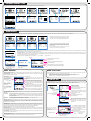
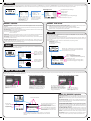
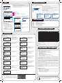
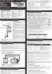
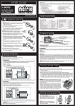
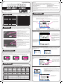
dischargE The adjustable high-performance discharge circuit (0.1 to 20.0A + 35A Pulse discharge) can be used for 1-14 cell NiMH/NiCd- and 1-4 cell Lixx-packs. The Pulsar Touch informs you about all the data relating to the battery pack, e.g. discharge time, capacity, average voltage and internal resistance. By discharging your battery pack on the Pulsar Touch after use, you obtain vital information about remaining capacity for optimizing your motor or gear ratio for the next run. This also maintains your battery packs in good condition. P1 PROFILE NAME . Discharge screen: DISCHARGE START DISCHARGE SETUP Current Pack.Volt Cutoff V. Cut-Temp START X _ DISCHARGE Capacity Current Voltage Avg.volt Resistance CHECK STATUS: : 20.0A : 7.4V/2s : 3.2V : 55°C BATTERY......ok Connection...ok the choosen settings will be indicated to avoid incorrect settings for the battery you want to discharge. Cancel the operation by pressing X in upper right corner! your charger checks if all connections and the battery itself are ok and if discharge process can be started. Time elapsed since start of discharge 00m05s 0030mAh 20.00A 07.50V 07.68V 0.0mΩ NEXT NEXT Discharge capcacity Discharge current Actual pack voltage Average voltage of your pack during discharging STOP Internal resistance of your pack DISCHARGE - explanations: DISCHARGE - further screens: Discharge Current: The discharge current can be set from 0.1 - 20.0A and 35A pulse. If not otherwise specified by the During running discharge process there is additional information available, by pressing „NEXT“ button you may access those. The available screens are (you jump to next by pressing „NEXT“ again): - Voltage of each cell in pack (if balancer is used!), for description see section „Balancer“. - Internal resistance of each cell in pack (if balancer is used!), for description see section „Balancer“. - Data View screens, , for description see section „View Last Data“. battery manufacturer, the max. discharge current can be set to 20.0A for racing cells (Sub-C size) in LiPo, LiFe and NiMH technology. However, lower grade cells and receiver-/transmitter battery packs you should use a lower the discharge current and should follow your battery manufacturer‘s recommmendations. Cut-Off Voltage: The cut-off voltage can be adjusted for all types and numbers of cells. We recommend a cut-off voltage of 0.9V/cell with NiMH/NiCd-batteries and 3.2V/cell with LiPo-batteries. As an example: - 5.4V for a 6-cell NiMH/NiCd-pack - 6.4V for a 2S LiPo-pack. Temperature: by using the optional temperature sensor, you can set a maximum temperature which the battery is not allowed to reach during discharging. If battery reaches that temperature, the discharge process will be stopped. Connections: make sure you use high-quality wire and connectors for maximum accuracy, a poor connector or poor wire may create heat and affect the accuracy, Discharge Wattage limitation: the discharge wattage is limited to 150W (Watts = Voltage x Current / e.g. for 7.4Vx20A = 148W)), this means packs with higher then 7.4V can not be discharged with 20A but the charger will automatically set the highest possible current by itself during discharging. balance cycle This fully automatic cycling/matching function allows you to determine the actual performance of your packs. Battery packs change during their life span or different batteries may vary slightly. Use the Pulsar Touch to detect the actual quality of your pack,.this prevents nasty surprises. The „Cycle“ function can of course be used for all types of cells. The “Cycle” mode uses the charge and discharge values of the currently selected programm, stored under “SETUP” and is of course fully adjustable in regards of sequence and pause/delay times between the different operations of the cycle function as well. At the end of the process, the packs „performance“ will be indicated to you by informing you about: - Discharge Capacity in mAh - Discharge Time - Average Voltage during discharging - Internal resistance P1 PROFILE NAME You can simply balance your 2S to 4S LiPo- and LiFePo-batteries using the integrated balancer. The Pulsar Touch indicates voltage and internal resistance for each cell in your pack. P1 PROFILE NAME P1 BALANCE [1/2] X 1s:0.000V 3s:0.000V START ▼4s:0.000V Gap 0.000V STOP NEXT P1 1s: 2s: 3s: 4s: BALANCE [2/2] X 0.0mΩ 0.0mΩ 0.0mΩ 0.0mΩ NEXT Automatic Cycle. as adjusted in Setup, the screens look identical as during regular charge- or discharge operation but additional text reminds you that you are in „Cycle“ mode. START indication of voltage of each cell, gap between the worst two cells and graphical indication of difference. ▲2s:0.000V BALANCE VIEW CYCLE SETUP . . indication of resistance of each cell and graphical indication of difference. P1 CYCLE Direction : Cycles : Chg Delay : Dischg Delay: NEXT X CD 01 10min 10min Select required sequence: C ⇨D = Charge, followed by discharging D ⇨C = Discharge, followed by charging ..D:C ⇨C = Initial Discharge, followed by charge/discharge Number of Cycles (1 to 10) Pause time before charging, after discharge (1-90min) Pause time before discharging, after charge (1-90min) SET STOP motor - esc - servo check The Pulsar Touch incorporates, as the first charger, a fantastic feature which allows you to check your brushless motors sensors and even measure motor rpm! In combination with the built-in receiver simulator port you can even check speed-controls for correct function. The receiver simulator port also allows the check of servo‘s. connect a brushless motor direct to the „BL Motor Sensor Port“ using a standard brushless motor sensor wire. The sensor check is simple as the sensors get measured while you rotate the shaft by hand! Black connect servo direct to connector port, be careful with correct polarity (black/minus must be on right side) P1 PROFILE NAME motor RPM measurement can only work by using an optional „hall sensor wire splitter“. You can of course connect your motor and speed-control as in normal use to check your speed-controls and motors condition but you simply get no RPM indication. MOTOR-ESC-SERVO X Signal Min : 1100 Signal Max : 1900 Max. pulse width: - range: 1500 - 2300ms SET connect speed-control direct to connector port, be careful with correct polarity (black/minus must be on right side) MOTOR - ESC - SERVO CHECK - explanations: . MOTOR-ESC-SERVO SETUP START Min. pulse width: - range: 700 - 1500ms Connection - BL Speedo & Motor Check (incl RPM): Black Connection - BL Motor Sensor check: Connection - Servo Test: Battery Connection: if you want to check full function of your motor and/or speed-control you need to connect your regular battery to the speed-control as the Pulsar Touch doesn‘t provide the high power to the speed-control but only the signals! selected pulse width values Speed Control Setup: you need to make your regular speed-control setup, so the speed-control learns the Pulsar Touch‘s neutral, full throttle and full brake points, if you want to check your speed-control. MOTOR-ESC-SERVO X 1100 1500 1900 Motor Sensors Rpm OK 0 „OK“ indicates that the hall-sensors inside your connected brushless motor work fine. After connecting your motor to the sensor port, you can rotate the shaft by hand. Here the measured RPM, when testing together with a speed-control will be indicated. Very useful to check your motor and/or speed-control for correct operation! the indicated black box is your „trigger“ (throttle or steering), you can drag it left & right with your finger and therefore alter the PWM output of the receiver simulator port which. Speed Control On/Off Switch: some speed-controls need to have on/off switch in Off position, when connecting to Pulsar Touch (as it supplies it‘s own BEC!). So please make sure you test with switch in „OFF“ position first and if all works as it should this is fine for your speed-control. If your speed-control is dark when in off position, you should try on „ON“ positino. BL Motor RPM Measurement: motor RPM measurement can only work by using an optional „hall sensor wire splitter“.LRP will release such an optional small device. You can of course connect your motor and speed-control as in normal use to check your speed-controls and motors condition but you simply get no RPM indication. Connections: make sure you use high-quality wire and connectors for maximum accuracy, a poor connector or poor wire may create heat and affect the accuracy,