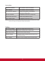
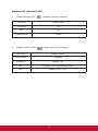
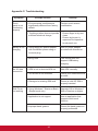
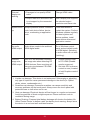
1
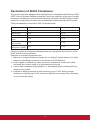
ViewPad 10pro
User Guide
Model No. VS14140
Compliance Information
CE Conformity for European Countries
The device complies with the EMC Directive 2004/108/EC and Low Voltage
Directive 2006/95/EC.
R&TTE Compliance Statement
2200
This wireless module device complies with the Essential Requirements of the R&TTE
Directive of the European Union (1999/5/EC). This equipment meets the following
conformance standards:
EN 301 489
EN 301 489
EN50361
EN301448
EN301908
EN301489
EN300328
EN62311
Caution
Risk of explosion if battery replaced aced by an incorrect type.
Dispose of used batteries according to the instructions.
Notified Countries: Germany, UK, Netherlands, Belgium, Sweden, Denmark, Finland,
France, Italy, Spain, Austria, Ireland, Portugal, Greece, Luxembourg, Estonia, Latvia,
Lithuania, Czech Republic, Slovakia, Slovenia, Hungary, Poland and Malta.
Following information is only for EU-member states:
The mark is in compliance with the Waste Electrical and Electronic
Equipment Directive 2002/96/EC (WEEE).
The mark indicates the requirement NOT to dispose the equipment
including any spent or discarded batteries or accumulators as unsorted
municipal waste, but use the return and collection systems available.
If the batteries, accumulators and button cells included with this
equipment, display the chemical symbol Hg, Cd, or Pb, then it means that
the battery has a heavy metal content of more than 0.0005% Mercury or
more than, 0.002% Cadmium, or more than 0.004% Lead.
Products with 2.4–GHz Wireless LAN Devices
For 2.4–GHz wireless LAN operation of this product, certain restrictions apply. This
equipment may use the entire–2400–MHz to 2483.5–MHz frequency band (channels
1 through 13) for indoor applications. For outdoor use, only 2400-2454 MHz
frequency band (channels 1-9) may be used. For the latest requirements, see http://
www.art-telecom.fr.
i
Important Safety Instructions
1.
2.
3.
4.
5.
6.
7.
8.
9.
10.
11.
12.
13.
14.
15.
16.
17.
18.
19.
20.
DO NOT place objects on top of the ViewPad, as objects may scratch the
screen.
DO NOT expose the ViewPad to dirty or dusty environments.
DO NOT place the ViewPad on an uneven or unstable surface.
DO NOT insert any foreign objects into the ViewPad.
DO NOT expose the ViewPad to strong magnetic or electrical field.
DO NOT expose the ViewPad to direct sunlight as it can damage the LCD
Screen.
Keep it away from heat sources.
SAFE TEMPERATURE: This ViewPad should only be used in environments
with ambient temperatures between 0°C (32°F) and 40°C(104°F).
DO NOT use the ViewPad in the rain.
Please check with your Local Authority or retailer for proper disposal of
electronic products.
The ViewPad and the adapter may produce some heat during normal operation
or charging. DO NOT leave the ViewPad on your lap to prevent discomfort or
injury from heat exposure.
POWER INPUT RATING: Refer to the rating label on the ViewPad and be sure
that the power adapter complies with the rating. Only use accessories specified
by the manufacturer.
DO NOT use a pen or any sharp object to tap the screen.
Clean the touch screen with a soft cloth. If needed, dampen the cloth slightly
before cleaning. Never use abrasives or cleaning solutions.
Always power off the ViewPad to install or remove external devices that do not
support hot-plug.
Disconnect the ViewPad from an electrical outlet and power off before cleaning
the ViewPad.
DO NOT disassemble the ViewPad, only a certified service technician should
perform repair.
The ViewPad has apertures to disperse heat. DO NOT block the ViewPad
ventilation, the ViewPad may become hot and malfunction as a result.
Risk of explosion if battery replaced by an incorrect type. Dispose of used
batteries according to the instructions.
Users have to use the connection to USB interfaces with USB 2.0 version or
higher.
PLUGGABLE EQUIPMENT, the socket-outlet shell be installed near the
equipment and shall be easily accessible.
ii
Declaration of RoHS Compliance
This product has been designed and manufactured in compliance with Directive 2002/
95/EC of the European Parliament and the Council on restriction of the use of certain
hazardous substances in electrical and electronic equipment (RoHS Directive) and is
deemed to comply with the maximum concentration values issued by the European
Technical Adaptation Committee (TAC) as shown below:
Substance
Proposed Maximum Concentration
Actual Concentration
Lead (Pb)
0,1%
< 0,1%
Mercury (Hg)
0,1%
< 0,1%
Cadmium (Cd)
0,01%
< 0,01%
Hexavalent Chromium
0,1%
(Cr6+)
< 0,1%
Polybrominated biphenyls (PBB)
0,1%
< 0,1%
Polybrominated diphenyl ethers (PBDE)
0,1%
< 0,1%
Certain components of products as stated above are exempted under the Annex of the
RoHS Directives as noted below:
Examples of exempted components are:
1. Mercury in compact fluorescent lamps not exceeding 5 mg per lamp and in other
lamps not specifically mentioned in the Annex of RoHS Directive.
2. Lead in glass of cathode ray tubes, electronic components, fluorescent tubes,
and electronic ceramic parts (e.g. piezoelectronic devices).
3. Lead in high temperature type solders (i.e. lead-based alloys containing 85% by
weight or more lead).
4. Lead as an allotting element in steel containing up to 0.35% lead by weight,
aluminium containing up to 0.4% lead by weight and as a cooper alloy containing
up to 4% lead by weight.
iii
Copyright Information
Copyright © ViewSonic® Corporation, 2011. All rights reserved.
ViewSonic®, the three birds logo, On View®, ViewMatch™, and ViewMeter® are
registered trademarks of ViewSonic® Corporation.
Android is a trademark of Google Inc. Use of this trademark is subject to Google
Permissions.
This product has an Android™ platform based on Linux, which can be expanded by a
varietyof JME-based application SW.
All products use in this device and trademarks mentioned herein are trademarks or
registered trademarks of their respective owners.
Google™, the Google logo, Android™, the Android logo and Gmail™ are trademarks
of Google Inc. Use of this trademark is subject to Google Permissions.
Wi-Fi and the Wi-Fi CERTIFIED logo are registered trademarks of the Wireless
Fidelity Alliance.
microSD™ is a trademark of SD Card Association.
Bluetooth and the Bluetooth logo are trademarks owned by Bluetooth SIG, Inc.
The prediction engine of the input method is TOUCHPAL, provided by COOTEK.
Disclaimer: ViewSonic Corporation shall not be liable for technical or editorial errors
or omissions contained herein; nor for incidental or consequential damages resulting
from furnishing this material, or the performance or use of this product.
In the interest of continuing product improvement, ViewSonic Corporation reserves
the right to change product specifications without notice. Information in this document
may change without notice.
No part of this document may be copied, reproduced, or transmitted by any means,
for any purpose without prior written permission from ViewSonic Corporation.
Product Registration
To meet your future needs, and to receive any additional product information as it
becomes available, please register your product on the Internet at: www.viewsonic.
com.
For Your Records
Product Name:
Model Number:
Document Number:
Serial Number:
Purchase Date:
ViewPad 10pro
VS14140
ViewPad 10pro_UG_ENG Rev. 1A 04-20-11
_______________________________
_______________________________
Product disposal at end of product life
ViewSonic respects the environment and is committed to working and living green. Thank you for
being part of Smarter, Greener Computing. Please visit ViewSonic website to learn more.
USA & Canada: http://www.viewsonic.com/company/green/recycle-program/
Europe: http://www.viewsoniceurope.com/uk/support/recycling-information/
Taiwan: http://recycle.epa.gov.tw/recycle/index2.aspx
iv
Table of Contents
Chapter 1: Product Overview
-
Package Contents
-
Control Buttons and Connectivity
Chapter 2: Setup
-
Power and Battery
-
Memory Card Installation
-
SIM Card Installation and Service Activation
-
Network Setup
Chapter 3: Basic Operation
-
Power Up, Standby and Off
Appendixes
A. BIOS Menu
B. Indicator Table
C.Troubleshooting
D. Caring Tips
1
Chapter 1: Product Overview
Package Contents
ViewPad 10pro
AC Charger
User Guide and
Installation Software
ViewPad Series Tablet
View
Qu Pad
ick
10
Star pro
t Gu
ide
PC System Requirements
Intel® Pentium® processor or
greater running on Windows®
Platform, 4x CD-ROM drive;
64MB or more of available
RAM; 800x600 color display.
Microsoft® Windows® 7 Professional
For distribution only with
a new ViewSonic® PC.
This disc contains 32-bit software only.
External Recovery Media Disc 1 of 1
Copyright © 2011, ViewSonic Corporation. All rights reserved. All trademarks,
registered
or otherwise, are the property of their respective companies. Disclaimer:
Support for these products
proViewSonic Corporation shall not be liable for technical or editorial reeors or
vided by ViewSonic®. omissions contained herein; nor for incidental or consequential damages resulting
from furnishing this meterial, or the performance or use of this product. In the
For technical support interest
informaof continuing product improvement, ViewSonic Corporation reserves the
right to change product specifications without notice. Information in this CD-ROM
tion, visit www.viewsonic.com
may change without notice, No part of this CD-ROM may be copied, reproduced, or
transmitted by any means, for any purpose without prior written permission of
ViewSonic Corporation.
Portions © 2011 Microsoft
Corpo03/14/11
• ViewPad_CD • Made in China
ration. All rights reserved. © 2011
ViewSonic
Part No. 03/14/11_VPD_Ver.1
Copyright © 2011, ViewSonic Corporation. All rights reserved. All trademarks,
registered or otherwise, are the property of their respective companies. Disclaimer:
ViewSonic Corporation shall not be liable for technical or editorial reeors or
omissions contained herein; nor for incidental or consequential damages resulting
from furnishing this meterial, or the performance or use of this product. In the
interest of continuing product improvement, ViewSonic Corporation reserves the
right to change product specifications without notice. Information in this CD-ROM
may change without notice, No part of this CD-ROM may be copied, reproduced, or
transmitted by any means, for any purpose without prior written permission of
ViewSonic Corporation.
03/14/11 • ViewPad_CD • Made in China
Quick Start Guide
1.
2.
3.
4.
Recovery DVD & Drivers CD
ViewPad 10pro Tablet
Universal AC Power Charger x1 (4 interchangeable plugs)
Quick Start Guide
Recovery DVD & Drivers CD
2
Control Buttons and Connectivity
Front
Left
Top
1.
Right
Bottom
Ambient Light Sensor
12. Micro SD Card Slot
2.Webcam
13.Reset
3.Search
14.Speakers
4.Return
15. Power Indicator
5.
Home Menu
16. Charger Indicator
6.
Settings Menu
17. Power Button
7.
Charger Jack
18. Hold and Ctrl+Alt+Del Button
8.
Earphone Jack
19. Volume DOWN
9.
Mini HDMI Output
20. Volume UP
10. USB Port
21.Microphone
11. SIM Card Slot
22. Docking Port
3
Chapter 2: Setup
Battery Replacement
Battery is permanently fixed to the device. Battery replacement should be performed
by an authorized ViewSonic service center. Please contact local ViewSonic customer
service for more information.
Charging Battery
The new battery is only partially charged out of box. To fully charge the battery,
please follow the below instruction.
1.
2.
Connect one end of the AC adapter to the charger jack.
Plug the other end of the AC adapter to the wall outlet to start charging.
Fig. 2.1 Charging Battery
When the battery is charging, the charge indicator LED will be flashing in amber; the
battery icon is also displayed in the status bar. When battery is fully charged, the
charge indicator LED will change to blue; if device is turned on, the battery icon will
be displayed as fully charged.
Note: Use only the provided AC power adapter for battery charging. The battery life may vary
depending on actual usage.
4
3G SIM Card & Memory Card
SIM card contains your network service details. MicroSD memory card provides
additional data storage space.
To install SIM/microSD card
1.
MicroSD only: Open card door.
2.
Insert SIM/MicroSD card as shown. Make sure the gold contacts are facing upward.
3.
MicroSD only: Close the card door.
Fig. 2-2 SIM & Micro SD Cards
To remove the SIM card
1.
Push to reject the SIM card from the slot.
To remove the memory card
1.
2.
3.
For safe removal, go to Windows task bar and right mouse click on
icon.
Select eject MicroSD card option.
After Windows prompts, “The device is now safe to remove” open the card
cover.
Push to eject the MicroSD card from the slot.
Note: Do not remove the memory card while it’s being accessed. Sudden removal of the memory
card may cause data loss or unpredictable system behavior.
5
Cellular Data Network (3G Data) Setup
Warning: ZTE 3G does not support hot-plug detect. Please make sure the device is
powered down when inserting the SIM. Inserting SIM while the device’s
power is ON will cause system shutdown.
1.
Power down the device.
2.
Insert SIM (gold contacts facing up).
3.
Power up the device.
4.
At Windows desktop, tap on
icon to open ZTE 3G control center.
Fig. 2-3 ZTE 3G Control Center
5.
After initializing, the SIM card will be detected.
Fig. 2-4 SIM Card Recognized
6.
Tap on
button to establish 3G data connection.
Fig. 2-5 3G Data Connected
6
Adding a New APN
If data connection is unable to establish, manual configuration needs to be
performed.
Fig. 2-6 Carrier APN is not found
Note: This device includes over 700+ worldwide APN settings. If your carrier APN is not in
the list, please obtain the following information from your network service provider.
-
-
-
1.
Tap on
2.
Tap on
Access Point Names (APN)
User Name
Password
icon to open setup menu.
button to add a new APN.
Fig. 2-7 Adding New APN
3.
In Connection Menu, key in Dial Number (*99#) and Config Name; key in APN,
User name and Password obtained from your network service provider.
Fig. 2-8 Connection Menu
4.Tap
5.
button to save the APN setting.
Go back to the main menu and tap on
7
button to make data connection.
Touch Panel Setup
The touch panel of this device has been factory calibrated. In most cases,
recalibration is not necessary. However, due to the nature of capacitive touch panel,
change of geographical location may require recalibration for the new environment
conditions.
If touch panel is experiencing improper behavior, please perform touch panel
calibration procedure as below.
1. Tap on
(ILITEK) icon to open touch panel calibration menu.
Fig. 2-9 Touch Panel Calibration Menu
2. Place the device on a flat table top. Avoid any touch contact to the touch panel
while performing the calibration.
3. Tap on “Calibration” to start the process.
4. When calibration is completed, message “Calibration OK” will be shown.
8
WiFi Setup
1.
2.
3.
4.
In Windows task bar, left click on
to bring up available access point menu.
Select the WiFi access point from the available WiFi network list.
Enter the password for the network if required.
Click on “Connect” to complete the connection.
Bluetooth
Bluetooth can be configured in the Control Panel. Please refer to Control Center
section for activating the Bluetooth.
Pairing Bluetooth Devices
1.
2.
3.
4.
5.
6.
7.
Ensure pairing devices’ Bluetooth feature is enabled.
Double tap on
located in Windows task bar to open the Bluetooth menu.
Tap “Add New Device” to scan all available Bluetooth devices in the area.
Select desired device from the discovered devices.
The screen will provide a PIN code for the connecting Bluetooth device. Enter
this code to connecting device. This screen will time out after a short period if
no action is taken.
Once the handshake is established, tap “Next” to complete.
If connecting with an audio device which only supports HSP/HFP (A2DP),
“Connect to phone audio” option will be displayed.
Note: Once the handshake has been established, connecting to the same device again will no longer
require entering the PIN.
9
Control Center
The control center provides a quick system overall status and communication
protocol (3G, WiFi and Bluetooth) setup.
Main Menu
Fig. 2-10 Control Center, Main Menu
Tap on an icon to enter the sub-menu.
-
System Info
-Battery
-
Thermal Condition
-Display
-
Power Management
-
Device Controller
10
System Info
Contains OS, BIOS, CPU and HD information.
Battery
Provide battery status and settings.
Fig. 2-11 Battery, Sub-Menu
Low Battery Warning Level Setting: Set the slide-bar for
low battery level.
Select warning notification type
1. OSD (Visual) Warning: Silent
2.
Sound Warning: Audible.
Save changes.
Set Battery settings back to default.
Gather battery usage data for battery time calculation.
11
Display
Provide display information and adjustments.
Fig. 2-12 Display, Sub-Menu
Tap to manually enable external video output (If plug &
play is not detected).
Adjust brightness level.
Power Management
Power management options.
12
Device Controller
Fig. 2-13 Device Controller, Sub-Menu
Wireless Card: Tap to enable/disable WiFi.
Bluetooth: Tap to enable/disable Bluetooth.
No function.
G-Sensor: Tap to enable/disable G-Sensor.
Light Sensor: Tap to enable/disable Light Sensor. Adjust display
brightness automatically based on room ambient light condition.
13
Chapter 3: Basic Operation
Power up and off
1.
Press on
button located at top of device to power up.
Warning: Do not turn off the device before it is fully booted or it may cause an error
on the next power up.
2. In Windows 7, click Start>Shutdown> or push the
button to power off.
Note 1: Windows can be configured to automatically shut down by single
press. Please use
Windows help & support (Keyword “Power”) for more power configuration information.
Note 2: Hard power off can be achieved by holding
down for >4 second.
Touch Screen Control
Tap: Quick single tap motion. Emulates left mouse click.
Tap & Hold: Press on open area for >4 seconds. Emulates right
mouse click.
Slide: Quick directional motion. Emulates scrolling.
Drag: Press on icon for >4 seconds then perform directional motion.
Emulates left mouse button hold.
Pinch: Two-points inward motion. Zoom in.
Spread: Two-points outward motion. Zoom out.
Note: An application can defines more complex hand gestures, availability based on application
support.
14
Virtual Keyboard
Virtual keyboard is located at upper left corner of Windows desktop. Drag the virtual
keyboard to center of Windows desktop for keyboard input.
Fig. 3-1 Virtual Keyboard in Desktop
Virtual keyboard icon will also pop up when enter text input section. Tap on keyboard
icon to bring forward the virtual keyboard.
Fig. 3-2 Virtual Keyboard icon
Windows 7 Professional: When user login menu is enabled, Ctrl+Alt+Del function
can be activated by pressing
button located at top of device for >4 seconds.
15
Navigation, Front and Side Control Buttons
The external buttons have different function in different OS.
Button
Location
BIOS & DOS
Windows
Bluestacks (Android)
Front
Up Arrow
Open Web Browser
Open Web Browser TBD
Front
Down Arrow
Return to Previous
Return to Previous
Front
ESC
Go to Desktop
Go to Home Desktop
Front
Enter
Open Tablet Control
Panel
Open Android Settings Menu
Top
Right Arrow
Volume Up
Volume Up
Top
Left Arrow
Volume Down
Volume Down
Android in Windows
1.
2.
3.
4.
Tap on
icon located in Windows desktop.
First time startup will take longer while initializing setup (One time setup).
Please refer to BlueStacks user guide for more information on Android
operation.
Tap on
icon to switch back to Windows.
16
Chapter 4 Appendix
Appendix A: BIOS Menu
Main Menu
-
-
Set time and date.
Provide following system configuration information.
1.
BIOS Version
2.
EC Version
3.
PCB Version
4.
Processor Type
5.
Processor Speed
6.
System Memory Speed
7.
L2 Cache RAM
8.
Total Memory
Advanced Menu
Quick Boot
Enable quick boot.
Diagnostic Splash
Screen
Boot-up splash screen select; graphics or text.
Diagnostic Summary
Screen
Diagnostic summary display enable/disable.
SATA Port
SATA device information.
17
Security Menu
Supervisor Password
Set= Enabled; Clear= No Password.
User Password
Set= Enabled; Clear= No Password.
Set Supervisor Password
Highest level password. Set password
restriction for Setup utility.
Set User Password
Set password restriction for Setup utility.
Authenticate User on boot
Enable startup password control.
HDD Password State
Set password restriction for HDD.
Warning: Please keep track of the passwords. BIOS reset will be required for password reset. Please
contact your IT Dept or PC specialist on BIOS reset information.
Exit Menu
Exit Saving Changes
Saves all changes and exit BIOS menu.
Exit Discarding Changes
Discard all changes and exit BIOS menu
Load Setup Defaults
Restore factory default settings.
Discard Changes
Discard all current changes and revert back to the
last saved settings.
Save Changes
Save all current changes without exit BIOS menu.
18
Appendix B: Indicator Table
1.
2.
Power Indicator LED (
, located on the top of device)
LED Color
Power Status
Solid Blue
ON
OFF
OFF
Flashing Blue
Sleep
Battery Indicator LED (
, located on the top of device)
LED Color
Battery Status
Solid Amber
Charging
Solid Blue
Battery Full
OFF
If Power is ON; using battery power.
OFF
If power is OFF; OFF.
19
Appendix C: Troubleshooting
Symptom
Touch
panel is not
functioning
properly
Battery is not
charging
No 3G data
connection
Multi Touch
not working
Possible Causes
1. Environmental conditions are
significantly different from factory
default.
Remedy
Perform touch screen
recalibration.
2. Touching surface does not provide - Ensure finger is dry and
sufficient electrical charge.
clean.
- Ensure stylus pen is
approved for capacitive
touch panel use.
1. Using wrong AC power adapter
with insufficient power rating or
incorrect plug.
Use AC power adapter
provided with this device.
2.Using USB.
This device does not
support USB battery
charging.
1. APN is not in device’s APN list.
Add APN manually.
2. 3G service is not activated.
Check your network service
provider.
3. Damaged or missing SIM card.
Ensure a valid 3G SIM is
properly inserted.
1. Using Windows 7 Starter or Basic
(Single touch only)
Upgrade OS to Windows 7
Home Premium or higher.
2.Application is not support
Use an application that
supports multi touch
function.
3.Improper hand gesture
Ensure the hand gesture is
properly performed.
20
External
display not
working
1.Damaged or low quality HDMI
cable
Change HDMI cable.
2.Output resolution and frame rate
is not support by the connected
display
Use a display that supports
the selected output
resolution and frame rate.
System locks
up
Multiple possible causes: Windows
code, Intel device failure, device
driver, overheating or application
code.
Push reset button to
restart the system. Perform
Windows updates regularly
for latest system and
device updates, install
latest device drivers and
application version.
No audio,
HDMI output
Audio driver needs to be switched
HDMI digital audio.
Go to Windows control
panel and set default audio
to HDMI digital. Switching
in audio mixer will not work
(Intel bug).
Incorrect
image size,
HDMI output
Intel GPU will automatic overscan
the image size when detecting CE
HDMI devices. Some monitors will
also auto-size between CE HDMI
and PC HDMI.
1. Ensure monitor is set
to PC HDMI (Disable
monitor overscan).
2. Set Intel GPU overscan
control to zero (Located
in Intel Graphics control
panel)
1. Liquids can damage: This device is not waterproof. Submerging or splashing
any type of liquid can cause permanent damage to the device (ie. Spilled
drinks, steam, condensation etc.).
2. Scratches can damage: Excessive scratches can cause sensitivity and
accuracy problems on the touch panel. Always cover the touch panel with
protected case or cloth when not in use.
3. Heat can damage: Electronic device will last longer in a cooler environment.
Avoid long periods of direct sunlight exposure. Ensure sufficient cool air
ventilation during usage.
4. Battery Draining: Frequent total battery drainage will shorten the battery life.
Utilize Control Center to define a safe low battery level warning. Always store
the device in a cool and well ventilated location.
21
Customer Support
For technical support or product service, see the table below or contact your reseller.
NOTE: You will need the product serial number.
Country/Region
Website
T = Telephone
F = FAX
Email
Australia/New Zealand
www.viewsonic.com.au
AUS= 1800 880 818
NZ= 0800 008 822
[email protected]
Canada
www.viewsonic.com
T (Toll-Free)= 1-866-463-4775
T (Toll)= 1-424-233-2533
F= 1-909-468-3757
[email protected]
Europe
www.viewsoniceurope.
com
www.viewsoniceurope.com/uk/support/call-desk/
Hong Kong
www.hk.viewsonic.com
T= 852 3102 2900
[email protected]
India
www.in.viewsonic.com
T= 1800 266 0101
[email protected]
Ireland (Eire)
www.viewsoniceurope.
com/uk/
www.viewsoniceurope.com/uk/
support/call-desk/
[email protected]
Korea
www.kr.viewsonic.com
T= 080 333 2131
[email protected]
Latin America
(Argentina)
www.viewsonic.com/la/
T= 0800-4441185
[email protected]
Latin America (Chile)
www.viewsonic.com/la/
T= 1230-020-7975
[email protected]
Latin America
(Columbia)
www.viewsonic.com/la/
T= 01800-9-157235
[email protected]
Latin America (Mexico)
www.viewsonic.com/la/
T= 001-8882328722
[email protected]
Renta y Datos, 29 SUR 721, COL. LA PAZ, 72160 PUEBLA, PUE. Tel: 01.222.891.55.77 CON 10 LINEAS
Electroser, Av Reforma No. 403Gx39 y 41, 97000 Mérida, Yucatán. Tel: 01.999.925.19.16
Other places please refer to http://www.viewsonic.com/la/soporte/index.htm#Mexico
Latin America (Peru)
www.viewsonic.com/la/
T= 0800-54565
[email protected]
Macau
www.hk.viewsonic.com
T= 853 2870 0303
[email protected]
Middle East
ap.viewsonic.com/me/
Contact your reseller
[email protected]
Puerto Rico & Virgin
Islands
www.viewsonic.com
T= 1-800-688-6688 (English)
T= 1-866-379-1304 (Spanish)
F= 1-909-468-3757
[email protected]
[email protected]
Singapore/Malaysia/
Thailand
www.ap.viewsonic.com
T= 65 6461 6044
[email protected]
South Africa
ap.viewsonic.com/za/
Contact your reseller
[email protected]
United Kingdom
www.viewsoniceurope.
com/uk/
www.viewsoniceurope.com/uk/
support/call-desk/
[email protected]
United States
www.viewsonic.com
T (Toll-Free)= 1-800-688-6688
T (Toll)= 1-424-233-2530
F= 1-909-468-3757
[email protected]
22
Limited Warranty
VIEWSONIC® ViewPad
What the warranty covers:
ViewSonic warrants its products to be free from defects in material and workmanship,
under normal use, during the warranty period. If a product proves to be defective in
material or workmanship during the warranty period, ViewSonic will, at its sole option,
repair or replace the product with a like product. Replacement product or parts may
include remanufactured or refurbished parts or components.The replacement unit will
be covered by the balance of the time remaining on the customer’s original limited
warranty. ViewSonic provides no warranty for the third-party software included with
the product or installed by the customer.
How long the warranty is effective:
ViewSonic ViewPad are warranted for at least 1 year for labor from the date of the
first customer purchase.
User is responsible for the back up of any data before returning the unit for service.
ViewSonic is not responsible for any data lost.
Who the warranty protects:
This warranty is valid only for the first consumer purchaser.
What the warranty does not cover:
1. Any product on which the serial number has been defaced, modified or
removed.
2. Damage, deterioration or malfunction resulting from:
a. Accident, misuse, neglect, fire, water, lightning, or other acts of nature,
unauthorized product modification, or failure to follow instructions supplied
with the product.
b. Repair or attempted repair by anyone not authorized by ViewSonic.
c. Causes external to the product, such as electric power fluctuations or failure.
d. Use of supplies or parts not meeting ViewSonic’s specifications.
e. Normal wear and tear.
f. Any other cause which does not relate to a product defect.
3. Any product exhibiting a condition commonly known as “image burn-in” which
results when a static image is displayed on the product for an extended period
of time.
4. Removal, installation, insurance, and set-up service charges.
How to get service:
1. For information about receiving service under warranty, contact ViewSonic
Customer Support (Please refer to the web site and Customer Support pages).
You will need to provide your product’s serial number.
2. To obtain warranty service, you will be required to provide (a) the original dated
sales slip, (b) your name, (c) your address, (d) a description of the problem, and
(e) the serial number of the product.
3. Take or ship the product freight prepaid in the original container to an authorized
ViewSonic service center or ViewSonic.
4. For additional information or the name of the nearest ViewSonic service center,
contact ViewSonic.
23
Limitation of implied warranties:
There are no warranties, express or implied, which extend beyond the description
contained herein including the implied warranty of merchantability and fitness for a
particular purpose.
Exclusion of damages:
ViewSonic’s liability is limited to the cost of repair or replacement of the product.
ViewSonic shall not be liable for:
1. Damage to other property caused by any defects in the product, damages
based upon inconvenience, loss of use of the product, loss of time, loss of
profits, loss of business opportunity, loss of goodwill, interference with business
relationships, or other commercial loss, even if advised of the possibility of such
damages.
2. Any other damages, whether incidental, consequential or otherwise.
3. Any claim against the customer by any other party.
4. Repair or attempted repair by anyone not authorized by ViewSonic.
Effect of state law:
This warranty gives you specific legal rights, and you may also have other rights
which vary from state to state. Some states do not allow limitations on implied
warranties and/or do not allow the exclusion of incidental or consequential damages,
so the above limitations and exclusions may not apply to you.
Sales outside the U.S.A. and Canada:
For warranty information and service on ViewSonic products sold outside of the
U.S.A. and Canada, contact ViewSonic or your local ViewSonic dealer. The warranty
period for this product in mainland China (Hong Kong, Macao and Taiwan Excluded)
is subject to the terms and conditions of the Maintenance Guarantee Card.
For users in Europe and Russia, full details of warranty provided can be found in
www.viewsoniceurope.com under Support/Warranty Information.
4.3: ViewSonic TPC Warranty
TPC_LW01 Rev. 1A 06-20-08
24