1
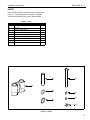
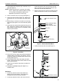
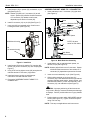
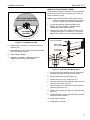
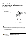
INSTALLATION INSTRUCTIONS
Y-Connector Accessory
(For Multi-Dual Arm Mounting Systems)
Model: KSA-1011
Specifications:
•
•
•
Installs to K-Series desk or wall mount.
Accommodates K-Series mounting arms (fixed
and height adjustable).
Weight capacity of 40 lbs (18 kg) total for all
equipment attached to KSA-1011.
KSA-1011
Shown with optional desk mount and mounting arms;
wall mount similar.
BEFORE YOU BEGIN
WARNING: It is the installer’s responsibility to make sure all components are properly assembled and installed
using the instructions provided. Failure to read, thoroughly understand, and follow all instructions can result in
serious personal injury, damage to equipment, or voiding of factory warranty.
•
If you have any questions about this these instructions or your specific installation, contact Chief Manufacturing
at 1-800-582-6480 or 952-894-6280.
CHIEF MANUFACTURING INC.
1-800-582-6480 952-894-6280 FAX 952-894-6918
8401 EAGLE CREEK PARKWAY, STE 700
SAVAGE, MINNESOTA 55378 USA
8807-000034
2006 Chief Manufacturing
www.chiefmfg.com
03/06
Model: KSA-1011
Installation Instructions
IMPORTANT WARNINGS AND CAUTIONS!
WARNING: A WARNING alerts you to the possibility of serious injury or death if you do not follow the instructions.
CAUTION: A CAUTION alerts you to the possibility of damage or destruction of equipment if you do not follow the
corresponding instructions.
WARNING: Exceeding the weight capacity can result in serious personal injury or damage to equipment! It is the
installer’s responsibility to make sure the combined weight of all components attached to the KSA-1011 (including
both displays and interfaces) does not exceed 40 lbs (18 kg).
•
The weight capacity of the KSA-1011 may be LIMITED to the lowest weight capacity of any other component
located between the KSA-1011 and the supporting structure!
WARNING: Allowing any part of your body or component cables to be caught between movable parts can result in
serious personal injury or damage to equipment!
TOOLS REQUIRED FOR INSTALLATION
•
•
•
Pencil (with eraser; for desk mount)
3/16" Hex Key (included with desk and wall mount)
2.5mm Hex Key (included with desk mount)
NOTE: Other tools may be required depending on your method of installation.
2
Installation Instructions
Model: KSA-1011
PARTS
After unpacking carton, inspect and verify contents (See
Figure 1). If any listed parts are missing or damaged,
contact Chief Customer Service at 1-800-582-6480.
Table 1: Parts
Item
Description
Qty
10
Y-CONNECTOR
1
20
PIN, Pivot
1
30
SPACER, UHMW (plastic)
1
40
WASHER, Lock, External Tooth, 5/8"
5
50
SCREW, Button Head Cap, 5/16"-18 x 3-3/4"
1
60
WASHER, 5/16", UHMW (plastic)
1
70
WASHER, 5/16", Stainless Steel
2
80
NUT, Lock, Nylock, 5/16"-18
1
MOUNT, Desk or Wall (Required, not included)
1-2
20
50
10
30
60
70
40
80
Figure 1: Parts
3
Model: KSA-1011
Installation Instructions
ASSEMBLY
ASSEMBLE Y-CONNECTOR TO MOUNT
Y-Connector (10) may be installed to either a desk or wall
mount (mount not included). See applicable assembly
instructions that follow.
NOTE: After mount arm is removed, nut can be retrieved
by turning desk mount housing upside down.
4. Remove stop screw and stop collar from mount arm
(See Figure 2). These will not be reused with Yconnector (10).
5. Using 2.5mm hex key, remove and retain desk mount
base plate and attach screws (See Figure 3).
Desk Mount
1. If previously attached, disconnect cables from
display, then remove display. See instructions
included with desk mount and/or interface.
Desk Mount
Housing
2. If previously attached, loosen (do not remove) clamp
attach screw (See Figure 2). Remove desk mount
from desk. See instructions included with desk
mount.
Base Plate
Mount Arm Attach Screw
Washer (Stainless Steel)
Washer (Plastic)
Washer (Stainless Steel)
Clamp
Attach Screws
(3 places)
Mount Arm
Figure 3: Desk Mount Base Plate
Pin
Stop
Collar Stop
Screw
6. Turn desk mount housing right side up and install pin
(20) into housing (See Figure 4).
Spacer
Stop Plate
Clamp Attach Screw
50
Desk Mount Housing
70
60
70
10
Nut
Figure 2: Disassemble Desk Mount
3. Turn mount assembly upside down and place in your
lap. With one hand, grasp desk mount housing and
lift slightly off lap. With other hand, using 3/16" hex
key, loosen and remove mount arm attach screw and
other related items (See Figure 2). Retain all items,
except stop plate, for later mount arm assembly.
NOTE: Slightly lifting desk mount housing will keep nut in
recessed cavity, assisting screw removal.
4
40 or
30
20
Desk Mount Housing
Figure 4: Assemble Y-Connector to Desk Mount
Installation Instructions
Model: KSA-1011
7. Install washer (40) or spacer (30), as desired, on pin
(20) (See Figure 4).
NOTE: Washer (40) will lock Y-connector (10) to desk
mount. Spacer (30) will allow limited movement
of Y-connector (10) relative to desk mount,
dependent upon tension of screw (50).
screw and remove wall mount housing from wall
plate. Do NOT remove wall plate from wall. See
instructions included with wall mount.
3. Remove mount arm from wall mount (See Figure 6).
Retain all hardware for later mount arm assembly.
8. Install Y-connector (10) on pin (20) (See Figure 4).
9. Install screw (50) through washer (70), washer (60),
and washer (70), into Y-connector (10) (See Figure
4).
Mount Arm Attach Screw
10. While holding Y-connector (10), desk mount housing,
and screw (50) together, turn entire assembly upside
down.
Washer (Stainless Steel)
Washer (Plastic)
Washer (Stainless Steel)
11. Insert eraser end of pencil into plastic lock ring of nut
(80). Using pencil, thread nut (80) onto end of screw
(50) several turns (See Figure 5). If necessary, rotate
clamp to permit access.
Mount Arm
Spacer
Desk Mount
Housing
Pin
Nut
Wall Mount Housing
Figure 6: Disassemble Wall Mount
4. Install pin (20) into wall mount (See Figure 7).
50
Clamp
80 (in recessed cavity)
Figure 5: Install Nut
50
12. Using 3/16" hex key, tighten screw (50) as required to
maintain desired Y-connector (10) position. Ensure
nut (80) fully seats into recessed cavity of desk mount
housing (See Figure 5).
70
60
70
13. Install retained desk mount base plate and attach
screws. Ensure clamp faces center of desk mount as
shown (See Figure 3).
10
14. Install mount to desk per instructions included with
desk mount.
40 or
15. Proceed to "ASSEMBLE MOUNT ARMS TO YCONNECTOR."
30
20
Wall Mount
1. If previously attached, disconnect cables from
display, then remove display. See instructions
included with wall mount and/or interface.
2. If previously attached, loosen (do not remove) set
80
Wall Mount Housing
Figure 7: Assemble Y-Connector to Wall Mount
5
Model: KSA-1011
5. Install washer (40) or spacer (30), as desired, on pin
(20) (See Figure 7).
NOTE: Washer (40) will lock Y-connector (10) to wall
mount. Spacer (30) will allow limited movement
of Y-connector (10) relative to wall mount,
dependent upon tension of screw (50).
6. Install Y-connector (10) on pin (20) (See Figure 7).
7. Insert nut (80) into recessed cavity of wall mount
housing as shown (See Figure 8).
Installation Instructions
ASSEMBLE MOUNT ARMS TO Y-CONNECTOR
1. Insert retained pin into Y-connector (10) upper bore
(See Figure 9).
Mount Arm Assembly
Screw
Washer (Stainless Steel)
Washer (plastic)
Washer (Stainless Steel)
40 or
Plastic Spacer
Pin
Wall Mount Housing
10
80
(in recessed cavity)
NOTE: All parts
same for both sides.
Nut
Desk Mount
(Wall Mount similar)
Figure 9: Multi-Dual Arm Assembly
Figure 8: Install Nut
8. Install screw (50) through washer (70), washer (60),
washer (70), and Y-connector (10), into nut (80) (See
Figure 7).
9. Using 3/16" hex key tighten screw (50) as required to
maintain desired Y-connector (10) position.
10. Install wall mount housing to wall plate per
instructions included with wall mount.
11. Proceed to "ASSEMBLE MOUNT ARMS TO YCONNECTOR."
2. Install washer (40) or retained plastic spacer, as
desired, on pin (See Figure 9).
NOTE: Washer (40) will lock arm to Y-connector. Spacer
will allow limited movement of arm relative to Yconnector (10), dependent upon tension of screw.
3. Insert mount arm assembly on pin (See Figure 9).
4. While holding retained nut in lower bore of Yconnector (10), insert retained screw through retained
washers (stainless steel washer, plastic washer, and
stainless steel washer), mount arm assembly, and Yconnector (10), into retained nut (See Figure 9).
CAUTION: Improper positioning of desk mount arm
may result in failure of mount and subsequent damage
to displays. Do NOT position either arm in gray shaded
area.
5. Position desk mount arm within UNSHADED area as
shown (See Figure 10). Tighten screw as required
using 3/16" hex key.
NOTE: This step not applicable to wall mount arms.
6
Installation Instructions
Model: KSA-1011
MODIFICATION OF MOUNT ARMS
If desired, each mount arm assembly may be modified to
prevent movement of one arm relative to the other arm
(without loosening screw).
DO NOT POSITION EITHER
ARM IN GRAY SHADED AREA
NOTE: Spacer will allow limited movement of one arm
relative to the other arm, dependent upon tension
of screw. Washer (40) will lock arms together.
1. If previously attached, disconnect cables from
display, then remove display. See instructions
included with mount and/or interface.
ALLOWABLE
ARM AREA
2. Using 3/16" hex key, loosen screw until nut can be
removed (See Figure 11). Retain nut. Screw and
washers may remain in outer mount arm assembly.
Screw & Washers
Figure 10: Allowable Arm Area
6. Repeat Steps 1. through 5. for second mount arm
assembly (10).
7. Install displays to mount. See instructions included
with mount and/or interface.
Outer mount
arm assembly
Inner mount
arm assembly
Spacer or
8. Install cables to display.
40
Pin
9. Assembly is complete. If desired, proceed to
"MODIFICATION OF MOUNT ARMS."
Nut
Figure 11: Multi-Dual Arm Modification
3. Lift outer mount arm assembly from pin (with screw
and washers) and place on protective surface.
4. Remove spacer from pin (See Figure 11).
5. Install washer (40) on pin (See Figure 11).
6. Re-install outer mount arm assembly (with screw and
washers) on pin (See Figure 11).
7. Insert and hold nut in lower bore of inner mount arm
assembly (See Figure 11).
8. Tighten screw as required using 3/16" hex key (See
Figure 11).
9. Install display(s) to mount. See instructions included
with mount and/or interface.
10. Install cables to display.
11. Modification is complete.
7
Model: KSA-1011
8
Installation Instructions