
1
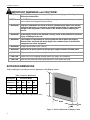
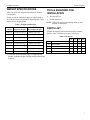
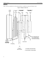
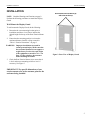
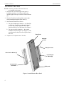
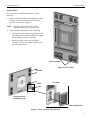
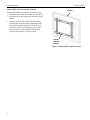
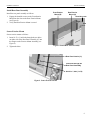
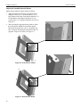
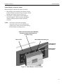
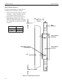
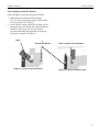
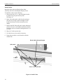
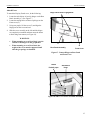
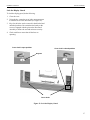
INSTALLATION
INSTRUCTIONS
DGC Series Display Guard™ Enclosures
DGC32, DGC42, DGC-50 and DGC-65
The Display Guard series of enclosures are designed to protect flat panel displays in high-risk
environments. The series is available in three sizes:
DGC-32: designed for 32-inch display models
DGC-42: designed for 42-inch display models
DGC-50: designed for 50-inch display models
DGC-65: designed for 65-inch display models
The enclosures are supplied as a fixed wall display enclosure. Accessories, such as the ceiling mount and
post assembly, are sold separately.
These enclosures provide excellent security and protection while providing easy viewing and access for
adjustments and display maintenance. The enclosures are also equipped with a security locks to protect the
display from inadvertent scratches and guard against theft.
Display Guard – Closed
Display Guard – Opened
BEFORE YOU BEGIN
CAUTION: To prevent damage to your display and Display Guard, which could affect or void the
Factory warranty, thoroughly study all instructions and illustrations before you begin to install
the mount. Pay particular attention to the Warnings and Cautions in this document.
CAUTION! The maximum weight capacity of the Display Guard fixed wall mounts is located in Table 2.
Chief® is a registered trademark of Milestone AV Technologies, Inc. All rights reserved.
8831-000011 Rev C
Chief Manufacturing, a division of Milestone AV Technologies
©2008 Milestone AV Technologies
8401 Eagle Creek Parkway, Savage, MN 55378
www.chiefmfg.com
P: 800.582.6480 / 952.894.6280 F: 877.894.6918 / 952.894.6918
06/08
Installation Instructions
DGI-42 and DGI-50
IMPORTANT WARNINGS and CAUTIONS!
WARNING
A WARNING alerts you to the possibility of serious injury or death if you do not
follow the instructions.
CAUTION
A CAUTION alerts you to the possibility of damage or destruction of equipment if you
do not follow the corresponding instructions.
WARNING
Improper installation can result in serious personal injury! Make sure that the
structural members can support a redundant weight factor five times the total
weight of the equipment. If not, reinforce the structure before installing the
mount.
WARNING
If the Display Guard is not installed correctly, there is the potential for personal
injury or damage to the unit.
WARNING
The installer is responsible for verifying that the wall to which the Display
Guard will be anchored will safely support the combined load of all attached
components or other equipment.
WARNING
Weight Specifications (see Table 2).
WARNING
Watch out for pinch points. Do not put your fingers between movable parts.
WARNING
Make sure the mount is correctly oriented.
CAUTION
Check the unit for shipping damage before you begin the installation.
CAUTION
Use only the bolts that are provided and do not over-tighten the bolts.
EXTERIOR DIMENSIONS
Table 1 and Figure 1 provide the exterior dimensions of the Display Guard.
Table 1. Exterior Dimensions
Description
Enclosure Model
Exterior
dimensions
32”
42”
50”
65”
Height
27.63
31.94
36.94
44.38
Width
38.74
47.94
55.94
69.64
Depth
19.55
23.01
23.05
21.21
Height
Specifications are subject to change without notice
Width
Depth
Figure 1. Exterior Dimensions of Display Guard
2
Installation Instructions
DGI-42 and DGI-50
WEIGHT SPECIFICATIONS
Table 2 provides the weight specifications for Display
Guard models.
Do not exceed the maximum support weight, defined as
the combined load of all attached components that can be
installed in the Display Guard.
Table 2. Weight Specifications
TOOLS REQUIRED FOR
INSTALLATION
Allen wrench set
Socket wrench set
NOTE: Other tools may be required depending on your
method of installation.
Model
Enclosure Weight
Fixed Wall Mount
Max. Support Weight
DGC-32
125 lbs (56.70 kg)
400 lbs (181.4 kg)*
DGCA-32
145 lbs (65.78 kg)
400 lbs (181.4 kg)*
DGC-42
125 lbs (56.70 kg)
400 lbs (181.4 kg)*
DGCA-42
175 lbs (79.38 kg)
400 lbs (181.4 kg)*
DGC-50
155 lbs (70.31 kg)
400 lbs (181.4 kg)*
10
DGCA-50
195 lbs (88.45 kg)
400 lbs (181.4 kg)*
DGC-65
235 lbs (106.6 kg)
DGCA-65
295 lbs (133.8 kg)
PARTS LIST
Unpack the shipping carton and check for the contents
listed in Table 3 and shown in Figure 2 on Page 4.
Table 3. Parts List
32”
42”
50”
65”
QTY
QTY
QTY
QTY
GAS SPRINGS
1
1
1
1
20
DISPLAY COVER
1
1
1
1
600 lbs (272.2 kg)*
30
HOUSING with wall brackets
1
1
1
1
600 lbs (272.2 kg)*
40
DISPLAY INTERFACE
1
1
1
1
REF
DESCRIPTION
* Fixed wall mount maximum support weight capacity
includes combined weight of display being installed and
enclosure.
3
Installation Instructions
DGI-42 and DGI-50
PARTS
Figure 2 shows an exploded view of the major parts that are assembled to construct the Display Guard.
Figure 2. Display Guard Parts
Front
Cover
Display
not
included
G
Chief
Interface
Bracket
(Purchased
separately)
Interior Mount
Assembly
Exterior Mount
Assembly
Front*
Rear
E-1
D
Front
B
Rear
A
The combined parts
B, C, and D are the
Rear Panel Assembly
C
Rear Panel
F
Gas Spring
E-2
Front**
Interior Mount
4
* For LFDs 0-2.5 inches deep
** For LFDs 2.5-5.7 inches deep
Installation Instructions
DGI-42 and DGI-50
INSTALLATION
NOTE: Read the Warnings and Cautions on page 2.
Orient Rear Exterior Mount (A)
with slots at the top
Perform the following procedures to install the Display
Guard.
Wall Mount the Display Guard
To wall-mount the Display Guard, do the following:
1. Determine the exact mounting location prior to
installation and draw a level line to indicate the
desired height for the top of the Rear Exterior Mount
(A).
2. Ensure that the mounting position is at least the
minimum distance from the ceiling as noted in
“Table 1. Exterior Dimensions” on page 2.
WARNING: Improper installation can result in
serious personal injury! Make sure that
the structural framework can support a
weight factor five times the total weight
of the equipment as noted in Table 1 on
Page 2. If not, reinforce the structure
before installing the mount.
Figure 3. Rear View of Display Guard
3. Check the Rear Exterior Mount (A) to ensure that it
is level and correct mounting to achieve level if
necessary. See Figure 3.
IMPORTANT! For specific dimensions of rear
exterior mount refer to the customer print for the
enclosure being installed.
5
Installation Instructions
DGI-42 and DGI-50
Attach Mount to Rear Panel
NOTE: Omit this procedure if the Rear Panel was
pre-installed at the factory.
1. Determine the exact mounting location prior to
installation and draw a level line to indicate the
desired height for the top of the Rear Exterior Mount
(A).
2. Place the Front Exterior Mount (B) over the eight
studs protruding through the Rear Panel (C).
3. Select mount orientation as follows:
a. For proper landscape orientation — the shoulder
screws on the Front Exterior Mount (B) should
be at the top, with the split panel on the Rear
Panel Assembly (C) on the bottom. See Figure 4.
b. For proper portrait orientation — the mounts
should be rotated 90 degrees (see Figure 5), with
consideration for the preferred swing direction of
the cover.
4. Torque the ¼-20 Nylock nuts to 70 in-lbs.
Rear Panel
Shoulder
screws
¼-20 Nylock nuts
Rear Interior Mount (D)
Front Exterior
Mount (B)
Pre-mounted
¼-20 studs
Split panel
Figure 4. Attach Mount to Rear Panel
6
Installation Instructions
DGI-42 and DGI-50
Fan Location
To use the Display Guard in portrait mode, do the
following:
1. Remove two fans and filters and reposition as shown
in Figure 5. Ensure that the louvers and airflow
direction are as shown in Figure 6.
NOTE: The fans operate on 120 VAC, with a
maximum capacity of 104 CFM per fan.
2. For preventative maintenance, do the following:
a. Clean the filters at an interval appropriate to the
surrounding environmental conditions. Clogged
or dirty filters can cause overheating.
b. Remove the filter covers with a flat blade
screwdriver. Be sure to reinstall with the louver
openings facing down.
Fans on bottom
Figure 5. Fan Location
Exhaust
Intake
Fan detail
Display Guard in
landscape mode
Air flow direction
Figure 6. Louvers and Air Flow Direction
7
Installation Instructions
DGI-42 and DGI-50
Attach PSB-U Interface Bracket to Display
Display
To attach the PSB-U to the display, do the following:
1. Mount the PSB-U interface bracket onto the rear of
the display as per the instructions enclosed with the
bracket.
2. Connect audio and video cables after the display
installed after the display has been attached to the
Rear Panel Assembly if possible. The location of
connectors on the rear of the display may require
the hook-ups are made during the final hanging
operation of the display, while accessible.
PSB-U
Interface
Bracket
Figure 7. Mount PSB-U Interface Bracket
8
Installation Instructions
DGI-42 and DGI-50
Install Rear Panel Assembly
Front Exterior
Mount (B)
Install the rear panel assembly as follows:
1. Engage the shoulder screws on the Front Interior
Mount into the slots on the Rear Exterior Mount
(see Figure 8).
Rear Exterior
Mount (A)
Shoulder screw
2. Verify that Rear Exterior Mount is seated.
Slot
Secure Exterior Mount
Secure exterior mount as follows:
1. Insert 10-32 x ½ inch bolts through the two holes
on either side of the Rear Panel Assembly (C) into
the flanges on the Exterior Mount Assembly (see
Figure 9).
2. Tighten the bolts.
Figure 8. Install Rear Panel Assembly
Rear Panel interior (C)
Insert bolt through the
Rear Panel Assembly
#10-32 x ½ bolt (1 of 2)
Figure 9. Secure Exterior Mount
9
Installation Instructions
Adjust and Assemble Interior Mount
Adjust and assemble the interior mount as follows:
1. Adjust depth and elevation for your specific LFD
using the vertical (1 to 7) and horizontal (A to G)
hole patterns in the Deep Front Interior Mount (E-1).
For the Shallow Front Interior Mount (E-2), use
vertical holes 1 to 7 and horizontal holes A to D (see
Figure 10).
2. After selecting the appropriate hole patterns, fasten
the Front Interior Mount (E) to the Rear Interior
Mount (D) using the four ¼-20 x ½-inch bolts and
four ¼-20 nuts with attached tooth washers that are
supplied. Torque to 50 in-lbs (see Figure 11).
Figure 10. Front Interior Mount
Figure 11. Rear Interior Mount
10
DGI-42 and DGI-50
Installation Instructions
DGI-42 and DGI-50
Mount Display to Interior Mount
Mount the display to the interior mount as follows:
1. Mount display with installed Chief interface bracket
to Interior Mount Assembly (E) by inserting 4 slotted
bushings into keyhole slots (see Figure 12).
2. Seat properly, ensuring that all four bushing are
correctly engaged. Check clearances and display
centering and adjust interior mount location if
necessary.
NOTE: The location of the audio and display
connectors on the rear of your display may
require that you make the connections during
the final display mounting process.
PSB-U Interface Bracket [NOT SHOWN]
[Interface bracket shown below for
illustration only]
Rear of LFD
Interior Mount Assembly (E)
Slotted bushing
(4 locations)
Slotted keyhole
(4 locations)
Figure 12. Mount Display to Interior Mount
11
Installation Instructions
DGI-42 and DGI-50
Check Mount Clearances
Check the mount clearances to ensure they are
set within the specified limits as follows:
1. Check to ensure that the minimum value for
A and B is 1.7 inches. Maximum value for
C is 6.8 inches as shown in Figure 13.
2. If the display is not positioned within the
dimensions shown below, remove the
display and adjust the brackets accordingly
(see “Adjust and Assemble Interior Mount”
on page 10.
Display depth
Bracket
0-2.5"
Deep (E-1)
2.5-5.7"
Shallow (E-2)
C
(Max = 6.8
inches)
A (Min = 1.7)
Rear
Panel (C)
Exterior Mount
(A and B)
Adjustment holes on
Interior Mount
LFD
B (Min = 1.7 inches)
Figure 13. Check Mount Clearances
12
Interior Mount
(D and E)
Installation Instructions
DGI-42 and DGI-50
Secure Display to Interior Bracket
Secure the display to the interior bracket as follows:
1. Rotate the latch on the Front Interior Mount
(E-1 or E-2) over the bushing on the Chief bracket to
a vertical position. See Figure 14.
2. Secure latch in vertical position by inserting a zip-tie
through the holes in the latch and in the Front Interior
Mount (E). The zip-tie will secure the latch to
prevent unintentional disengagement of the display
from the front mount. See Figure 15.
Latch
E
Front Interior Mount
Latch in vertical secure position
Figure 14. Latch in Unlocked Position
Figure 15. Latch in Locked Position
13
Installation Instructions
DGI-42 and DGI-50
Install Cables
Install the cables after installing the Rear Panel
Assembly, but before mounting the Display Guard.
To install the cables, do the following:
1. Remove the four 8-32 x ¼ hex head bolts from the
top half of the split panel and lay aside.
See Figure 16.
2. Route video and speaker cables into the enclosure
from the rear leaving a sufficient length of cable
inside the enclosure to allow connection to the
display.
3. Replace top half of the split panel. Apply downward
pressure to create a seal around evenly spaced cables
as the four bolts are reinstalled and tightened to 12 to
15 in-lbs.
4. Plug in AC cord to power strip.
5. Use cable ties to secure cords as necessary.
6. Ensure that no cables or cords interfere with the
exhaust fans.
Route cables through the gap
Split panel
8-32 x ¼ hex head bolts
Figure 16. Install Cables
14
Installation Instructions
DGI-42 and DGI-50
Attach Cover
To attach the Display Guard cover, do the following:
Hinge halves before engagement
1. Locate the male halves of two slip hinges on the Rear
Panel Assembly (C). See Figure 17.
2. Locate the mating halves of those slip hinges on the
Front cover (G).
3. Using two people, lift the cover (G) and align the
hinge parts on the cover and case.
4. Slide the cover assembly to the left until the hinges
are completely assembled and then rotate the detent
to block hinge movement (see Figure 18).
WARNINGS:
When mounting cover to Rear Panel, exercise
caution so that fingers do not get pinched.
When mounting cover to Rear Panel, the
weight of the cover must be supported until
after the gas springs are installed.
C
G
Rear Panel Assembly
Front Cover
Figure 17. Connect Hinges on Rear Panel
and Front Cover
Detent
Partially open
Assembled
hinge
Figure 18. Slide Cover Left to Assemble the Hinges
15
Installation Instructions
DGI-42 and DGI-50
Mount Gas Springs
To mount the gas springs, do the following:
Cover (G)
Gas spring (F)
Rear Panel (C)
1. Hold the Cover (G) open (see Figure 19).
2. Install the two gas springs that are used to support the
cover in the open position.
3. Attach the larger diameter end of the gas springs to
the Cover (G).
4. Install each gas spring by pushing the socket end over
the ball on the Cover (G) and the Rear Panel (C). See
Figure 20.
5. To remove a socket, insert a flat blade screwdriver
under the retaining clip on the socket and pry the clip
away from the socket to disengage the ball (do not
pry clip off). See Figure 21.
Figure 19. Hold Cover Open
Ball
Socket
Figure 20. Attach Socket Ends
Retaining clip
Flat blade screwdriver
(for removal only)
Figure 21. Removing a Socket
16
Installation Instructions
DGI-42 and DGI-50
Lock the Display Guard
To lock the display guard, do the following:
1. Close the cover.
2. Using the key, rotate the cover locks one-quarter turn
to lock the cover to the Rear Panel (see Figure 22).
3. Keys for the locks can be removed in both locked and
unlocked positions. Be certain that the hooks on the
cover are engaged with the pins on the Rear Panel
Assembly to ensure the seal and enclosure security.
4. Check each fan to ensure that all the fans are
operating.
Cover lock in open position
Cover lock in closed position
Keyhole
Cover locks
Figure 22. Lock the Display Guard
17


![[OL46B] User Manual - English](http://vs1.manualzilla.com/store/data/005698665_1-52a04aa641441dd0417ba4f49a494031-150x150.png)