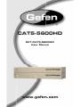
1
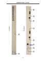
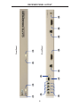
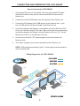
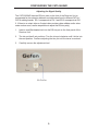
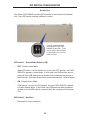
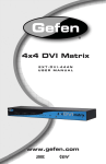
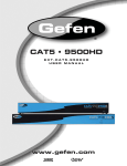
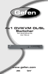
®
CAT5-5600HD
EXT-CAT5-5600HD
User Manual
www.gefen.com
ASKING FOR ASSISTANCE
Technical Support:
Telephone
(818) 772-9100
(800) 545-6900
Fax
(818) 772-9120
Technical Support Hours:
8:00 AM - 5:00 PM Monday - Friday, Pacific Time
Write To:
Gefen LLC
c/o Customer Service
20600 Nordhoff St
Chatsworth, CA 91311
www.gefen.com
[email protected]
Notice
Gefen LLC reserves the right to make changes in the hardware, packaging and
any accompanying documentation without prior written notice.
CAT5-5600HD is a trademark of Gefen LLC
© 2011 Gefen LLC, All Rights Reserved
All trademarks are the property of their respective owners
CONTENTS
1
Introduction
2
Operation Notes
3
Features
4
Sender Panel Layout
5
Sender Panel Descriptions
6
Receiver Panel Layout
7
Receiver Panel Descriptions
8
Connecting and Operating the CAT5-5600HD
8
Wiring Diagram
9
Adjusting the Signal Quality
10 DIP Switch Configuration
13 Network Cable Wiring Diagram
14 Rack Mount Installation
15 Specifications
16 Warranty
INTRODUCTION
Congratulations on your purchase of the CAT5-5600HD. Your complete satisfaction is very important to us.
Gefen
Gefen is a unique product line catering to the growing needs for innovative home
theater solutions. We specialize in total integration for your home theater, while
also focusing on going above and beyond customer expectations to ensure you
get the most from your hardware. We invite you to explore our distinct product
line and hope you find your solutions. Don’t see what you are looking for here?
Please call us so we can better assist you with your particular needs.
The Gefen CAT5-5600HD
Extend two DVI sources and USB 2.0 peripherals from any computer or KVM
device with the Gefen CAT5-5600HD Professional Series KVM extender. Extension is up to 200 feet (60 meters) using three (3) CAT-6a cables.
The Receiver Unit allows the connection of up to two DVI monitors and up to four
USB devices, expanding your workspace and increasing productivity in a postproduction and editing environment.
USB 2.0 data rates up to 480 Mbps are supported in addition to backward-compatibility with USB 1.1.
How It Works
Place the CAT5-5600HD Sender Unit next to the source. Use the included DVI
cables to connect the DVI source(s) to the Sender Unit. Use the supplied USB
cable to connect the Sender Unit to the USB host (source) device. Connect the
Receiver Unit to the DVI displays using DVI cables. Connect the USB devices
to the Receiver Unit. Connect the Sender Unit to the Receiver Unit using three
CAT-6 cables up to 200 feet. Connect the included locking power supplies to the
Sender and Receiver Units, then connect both power cables to available electrical outlets.
1
OPERATION NOTES
READ THESE NOTES BEFORE INSTALLING OR
OPERATING THE CAT5-5600HD
•
CAT-6a cables can be used up to 200 feet (60 meters).
•
CAT-5e cables can be used up to 150 feet (45 meters).
•
Shielded (STP) CAT-5e/CAT-6a is recommended. However, unshielded
(UTP) CAT-5e/CAT-6a is acceptable.
NOTE: Shielded cable has an advantage by providing immunity to
Electromagnetic Interference (EMI), cell phones and A/C motors.
•
The CAT5-5600HD only supports DVI-D signals. Analog DVI content is not
supported.
2
FEATURES
Features
•
Extends two DVI sources to 200 feet (60 meters) up to 1080p or 1920x1200
(using CAT-6a cables)
•
Extends USB 2.0 up to 200 feet (60 meters)
•
Backward-compatible with USB 1.1 devices
•
Works with any computer using DVI and USB
•
Supports the DDWG standard for DVI compliant monitors
•
Rack-mountable (includes rack ears)
Package Includes
(1) CAT5-5600HD - Sender Unit
(1) CAT5-5600HD - Receiver Unit
(2) 6 ft. DVI cable (M-M)
(1) 6 ft. USB cable (A-B)
(2) 5V DC Locking Power Supplies
(1) Set of Rack Ears
(1) User Manual
3
1
3
4
5
6
2
4
7
Back Panel
Front Panel
8
9
10
SENDER PANEL LAYOUT
SENDER PANEL DESCRIPTIONS
1
Power / Link 2 Indicator
When power is applied to the Sender Unit, this LED will glow bright red. Once a
DVI source is connected to the DVI 2 input, this LED will glow bright green.
2
Link 1 Indicator
When power is applied to the Sender Unit, this LED will glow bright red. Once a
DVI source is connected to the DVI 1 input, this LED will glow bright green.
3
USB Input Port
Connect the USB host device to this port.
4
USB Link Indicator
This LED will turn bright green once a USB link has been established
between the Sender Unit and the Receiver Unit. If the USB source device is
disconnected, then the LED will turn off.
5
USB / CAT-6 Link Output
Connects the USB / CAT-6 Link on the Sender Unit to the USB / CAT-6 Link on
the Receiver Unit using CAT-6 cabling.
6
Video 1 / CAT-6 Link Output
Connects the Video / CAT-6 Link on the Sender Unit to the Video / CAT-6 Link
on the Receiver Unit using CAT-6 cabling.
7
DVI 1 Input
Connect a DVI cable from the computer to this DVI-I connector.
8
Video 2 / CAT-6 Link Output
Connects the Video 2 / CAT-6 Link on the Sender Unit to the Video 2 / CAT-6
Link on the Receiver Unit using CAT-6 cabling.
9
DVI 2 Input
Connect a DVI cable from the computer to this DVI-I connector.
10 5 V DC Locking Power Connector
Connect the included 5 V DC locking power supply to this connector.
5
5
1
6
2
7
8
9
3
6
10
Back Panel
4
Front Panel
11
12
13
RECEIVER PANEL LAYOUT
RECEIVER PANEL DESCRIPTIONS
1
Power / Link 2 Indicator
When power is applied to the Receiver Unit, this LED will glow bright red. Once
a link has been established between the Sender Unit and the Receiver Unit, the
LED glows bright green.
2
Link 2 EQ Trim Pot
The EQ trim pot is used to equalize the signal on the DVI 2 output. See page 9
for details.
3
Link 1 Indicator
When power is applied to the Receiver Unit, this LED glows bright red. When
the link has been established between the Sender Unit and the Receiver Unit,
this LED glows bright green.
4
Link 1 EQ Trim Pot
The EQ trim pot is used to equalize the signal on the DVI 1 output. See page 9
for details.
5
USB Output Ports (1 - 4)
Connect USB devices to these ports.
6
USB Connection Indicators (1 - 4)
These LEDs will turn bright green when USB devices have been connected.
7
USB / CAT-6 Link Input
Connects the USB / CAT-6 Link on the Receiver Unit to the USB / CAT-6 Link on
the Sender Unit using CAT-6 cabling.
8
USB Link Indicator
This LED will turn bright green once a USB link between the Sender Unit and
the Receiver Unit has been made. If the USB link is lost, this LED will glow
bright red.
9
Video 1 / CAT-6 Link Input
Connects the Video / CAT-6 Link on the Receiver Unit to the Video / CAT-6 Link
on the Sender Unit using CAT-6 cabling.
10 DVI 1 Output
Connect a DVI display to this DVI-I connector.
11 Video 2 / CAT-6 Link Output
Connects the Video 2 / CAT-6 Link on the Receiver Unit to the Video 2 / CAT-6
Link on the Sender Unit using CAT-6 cabling.
12 DVI 2 Input
Connect a DVI display to this DVI-I connector.
13 5 V DC Locking Power Connector
Connect the included 5 V DC locking power supply to this connector.
7
CONNECTING AND OPERATING THE CAT5-5600HD
How to Connect the CAT5-5600HD
1.
Connect the DVI source to the Sender Unit using the included DVI cable.
Another DVI cable can be used to connect a second DVI source to the
Sender Unit.
2.
Connect the included USB cable from the computer to the Sender Unit.
3.
Connect the DVI display(s) and USB devices to the Receiver Unit. Up to
four (4) USB devices can be connected to the Receiver Unit.
4.
Connect the Sender and Receiver units together with up to 200 feet of CAT6a or up to 150 feet using CAT-5e cable. Be sure to make the corresponding
connections between the Sender Unit and Receiver Unit (e.g. DVI 1 on the
Sender Unit to DVI 1 on the Receiver Unit, etc).
5.
Connect the included 5 V DC power supplies to both the Sender and
Receiver units.
6.
The remote computer can now be controlled from the Receiver unit.
NOTE: USB cannot be extended by itself. A video signal must be present in
order to extend USB.
Wiring Diagram for the CAT5-5600HD
CAT-6 CABLE
USB CABLE
DVI CABLE
(Up To 200 FT)
Computer
Receiver
DVI Monitor
USB Mouse
Sender
DVI Monitor
USB Keyboard
USB External HDD
USB Printer
8
EXT-CAT5-5600HD
CONFIGURING THE CAT5-5600HD
Adjusting the Signal Quality
The CAT5-5600HD has two EQ trim pots on the front of the Receiver Unit to
compensate for the extension distance and cable skew found in different CAT-5e /
CAT-6a cabling brands. EQ 1 corresponds to DVI 1 and EQ 2 corresponds to DVI
2. If there is no output video or if output video contains video artifacts and/or video
noise such as snow, use the steps below to adjust the EQ trim pot(s).
1.
Insert a small flat-headed tool into the EQ trim pot on the front panel of the
Receiver Unit.
2.
The trim pot has 8 set positions. Turn the trim pot clockwise until it clicks into
the next position. Continue adjusting the trim pot until the issue is resolved.
3.
Carefully remove the adjustment tool.
EQ Trim Pot
9
DIP SWITCH CONFIGURATION
Sender Unit
The Gefen CAT5-5600HD contains DIP switches on the bottom of the Sender
Unit. Each DIP switch performs a different function.
Two DIP switches located
on the bottom of the CAT55600HD Sender Unit. There
are two sets of DIP switches
on the Sender Unit: One for
each DVI input.
DIP Switch 1 - Green Mode (Default = ON)
•
OFF - Enable Green Mode
When DIP switch 1 on the Sender Unt is set to the OFF position, the CAT55600HD is placed in Green Mode. In this mode, the USB devices are not
powered if the USB cable from the Sender Unit to the computer source is
disconnected. Automatic Power Mode consumes less than 1 Watt of power.
•
ON - Disable Green Mode
If DIP switch 1 is set to the ON position, then the CAT5-5600HD is placed
in Power Always Mode. In this mode, the USB ports are always powered
whether or not a USB cable is connected from the computer to the Sender
Unit.
DIP Switch 2 - Not Used
•
Reserved for future expansion.
10
DIP SWITCH CONFIGURATION
Receiver Unit
The Gefen CAT5-5600HD contains DIP switches on the bottom of the Sender
Unit. Each DIP switch performs a different function.
The four DIP switches located
on the bottom of the CAT55600HD Receiver Unit. There
are two sets of DIP switches
on the Receiver Unit: One for
each DVI output.
DIP Switch 1 - EDID Mode (Default = ON)
•
OFF - Local EDID Mode
When DIP switch 1 on the Sender Unt is set to the OFF position, the CAT55600HD uses the built-in Internal EDID stored in the Sender Unit.
•
ON - Pass Through Mode
If DIP switch 1 is set to the ON position, the EDID stored in display,
connected to the Receiver Unit, is copied to the DVI input of the Sender Unit.
11
DIP SWITCH CONFIGURATION
Receiver Unit
DIP Switch 2 - Color Depth (Default = OFF)
•
OFF - 8-bit Color
Disables Deep Color in the EDID. Deep Color management is only available
when Local EDID is being used (DIP 1 = OFF).
•
ON - 12-bit Color
Set DIP switch 2 to the ON position to enable Deep Color support. In Passthrough EDID Mode, setting DIP switch 2 to the ON position has no effect
since all EDID information is passed through.
DIP Switch 3 - Not Used
•
Reserved for future expansion.
DIP Switch 4 - Green Mode (Default = ON)
•
OFF - If DIP switch 4 is set to the OFF position, the CAT5-5600HD is placed
in Automatic Power Mode. In this mode, the USB devices are not powered if
the USB cable from the Sender Unit to the computer source is disconnected.
Green Mode consumes less than 1 Watt of power.
•
ON - If DIP switch 4 is set to the ON position, then the CAT5-5600HD is
placed in Power Always Mode. In this mode, the USB ports are always
powered whether or not a USB cable is connected from the computer to the
Sender Unit.
12
NETWORK CABLE WIRING DIAGRAM
Gefen recommends the TIA/EIA-568-B wiring option. Please adhere to the table
below when field-terminating the CAT-5e / CAT-6a cable for use with Gefen
products.
Pin
Color
1
Orange / White
2
Orange
3
Green / White
4
Blue
5
Blue / White
6
Green
7
Brown / White
8
Brown
CAT-5e / CAT-6a cabling comes in stranded and solid core types. Gefen
recommends using solid core cabling.
It is recommended to use one continuous run from one end to the other.
Connecting through a patch is not recommended.
13
RACK MOUNT INSTALLATION
Rack mount ears are provided for installation of this unit into a 1U rack mount
space.
1.
2.
3.
4.
Locate the side screws on the unit.
Remove the front 2 screws that are located closest to the front of the unit.
Using the removed screws, screw the rack mounting bracket into the unit.
Repeat the procedure on the opposite side of the unit.
1
Front of unit
Rear of unit
2
3
4
14
SPECIFICATIONS
Maximum Pixel Clock................................................................................165 MHz
Input Video Signal.....................................................................................1.2 V p-p
Input DDC Signal................................................................................5 V p-p (TTL)
Digital Video Inputs (Sender).............................................(2) DVI-I, 29-pin, female
Digital Video Outputs (Receiver).......................................(2) DVI-I, 29-pin, female
USB Input (Sender).................................................................................(1) Type B
USB Outputs (Receiver)..........................................................................(4) Type A
Video Link Indicators (Sender / Receiver).............(2) LED, multi-color, red / green
USB Link Indicators (Sender / Receiver)..........................................(6) LED, green
EQ Trim Pots (Receiver).................................................................(2) EQ 1 / EQ 2
Power Supply (Sender / Receiver)...............................................................5 V DC
Power Consumption................................................................20 W per unit (max.)
Operating Temperature..............................................................................0 - 40 °C
Dimensions (Sender / Receiver)...................................17” W x 1.75” H x 4.375” D
Shipping Weight..............................................................................................7 lbs.
15
WARRANTY
Gefen warrants the equipment it manufactures to be free from defects in material
and workmanship.
If equipment fails because of such defects and Gefen is notified within two (2)
years from the date of shipment, Gefen will, at its option, repair or replace the
equipment, provided that the equipment has not been subjected to mechanical,
electrical, or other abuse or modifications. Equipment that fails under conditions
other than those covered will be repaired at the current price of parts and labor in
effect at the time of repair. Such repairs are warranted for ninety (90) days from
the day of reshipment to the Buyer.
This warranty is in lieu of all other warranties expressed or implied, including
without limitation, any implied warranty or merchantability or fitness for any
particular purpose, all of which are expressly disclaimed.
1.
Proof of sale may be required in order to claim warranty.
2.
Customers outside the US are responsible for shipping charges to and from
Gefen.
3.
Copper cables are limited to a 30 day warranty and cables must be in their
original condition.
The information in this manual has been carefully checked and is believed to
be accurate. However, Gefen assumes no responsibility for any inaccuracies
that may be contained in this manual. In no event will Gefen be liable for
direct, indirect, special, incidental, or consequential damages resulting from
any defect or omission in this manual, even if advised of the possibility of such
damages. The technical information contained herein regarding the features and
specifications is subject to change without notice.
For the latest warranty coverage information, please visit Gefen’s Warranty web
page at http://www.gefen.com/kvm/aboutus/warranty.jsp
PRODUCT REGISTRATION
Please register your product online by visiting Gefen’s web site at
http://www.gefen.com/kvm/Registry/Registration.jsp
16
Pb