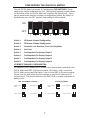
1
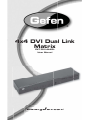
®
4x4 DVI Dual Link
Matrix
EXT-DVI-444DL
User Manual
www.gefen.com
f
ASKING FOR ASSISTANCE
Technical Support:
Telephone
(818) 772-9100
(800) 545-6900
Fax
(818) 772-9120
Technical Support Hours:
8:00 AM to 5:00 PM (PST) Monday thru Friday PST
Write To:
Gefen, LLC
c/o Customer Service
20600 Nordhoff St
Chatsworth, CA 91311
www.gefen.com
[email protected]
Notice
Gefen, LLC reserves the right to make changes in the hardware, packaging and
any accompanying documentation without prior written notice.
4x4 DVI DL Matrix is a trademark of Gefen, LLC
© 2011 Gefen, LLC. All rights reserved.
All trademarks are the property of their respective owners.
Rev X3
CONTENTS
1
Introduction
2
Operation Notes
3
Features
4
Panel Layout
5
Panel Descriptions
6
Connecting And Operating The 4x4 DVI DL Matrix
7
Configuring The 4x4 DVI DL Matrix
9
RS-232 Serial Control Interface
10 Rack Mount Installation
11 Specifications
12 Warranty
INTRODUCTION
Congratulations on your purchase of the 4x4 DVI DL Matrix. Your complete
satisfaction is very important to us.
Gefen
Gefen delivers innovative, progressive computer and electronics add-on solutions
that harness integration, extension, distribution and conversion technologies.
Gefen’s reliable, plug-and-play products supplement cross-platform computer
systems, professional audio/video environments and HDTV systems of all sizes
with hard-working solutions that are easy to implement and simple to operate.
The Gefen 4x4 DVI DL Matrix
Easily combine any four cross-platform Dual Link DVI video display outputs and
four Dual Link DVI digital displays without networking. Our 4x4 DVI Dual Link
Matrix provides a simple, reliable and highly effective method of creating multiple
Dual Link DVI display consoles, with each console capable of accessing any one
of the Dual Link DVI video sources at any time by remote control. You also have
the option of setting up the four displays locally or extending them with a Gefen
extender.
How It Works
The 4x4 DVI Dual Link Matrix has four Dual Link DVI inputs and four Dual Link
DVI outputs. You simply connect your four Dual Link DVI video sources to the
Switcher’s inputs, then connect your four Dual Link DVI displays to the Switcher’s
outputs.
1
OPERATION NOTES
READ THESE NOTES BEFORE INSTALLING OR
OPERATING THE 4X4 DVI DL MATRIX
•
The 4x4 DVI DL Matrix does not have any scaling functionality. All of the
attached monitors must be able to display the attached sources’ resolution.
For maximum compatibility it is recommended that only one compatible/
common resolution for all displays be used by all sources.
2
FEATURES
Features
•
Increases your productivity by letting you view any four Dual Link DVI video
sources on any four Dual Link DVI displays
•
Maintains highest resolution digital video with no loss of quality
•
Discrete IR Remote (included)
•
Supports video resolutions up to 3840x2400
•
Supports DDWG standards for DVI monitors
•
Includes rack ears
Package Includes
(1) 4x4 DVI Dual Link Matrix
(1) RMT-16IR
(1) 5V DC Power Supply
(4) 6 Foot Dual Link DVI cables
(1) Set Of Rack Ears
(1) User’s Manual
3
PANEL LAYOUT
Front Panel
1
2
3
4
5
6
7
Back Panel
8
9
10
11
12
13
4
14
15
16
17
PANEL DESCRIPTIONS
1
Display 1 Selected Source LED
The array of 4 LED’s correspond to the 4 source inputs on the back panel of the 4x4 DVI DL
Matrix. The currently selected source being displayed on DVI Output 1 will be indicated by an
active LED.
2
Display 2 Selected Source LED
The array of 4 LED’s correspond to the 4 source inputs on the back panel of the 4x4 DVI DL
Matrix. The currently selected source being displayed on DVI Output 2 will be indicated by an
active LED.
3
Display 3 Selected Source LED
The array of 4 LED’s correspond to the 4 source inputs on the back panel of the 4x4 DVI DL
Matrix. The currently selected source being displayed on DVI Output 3 will be indicated by an
active LED.
4
Display 4 Selected Source LED
The array of 4 LED’s correspond to the 4 source inputs on the back panel of the 4x4 DVI DL
Matrix. The currently selected source being displayed on DVI Output 4 will be indicated by an
active LED.
5
IR Receiver
This IR receiver will receive commands from the included RMT-16-IR remote control.
6
IR Extension Port
Connect an optional IR extension (part# EXT-RMT-EXTIR) to this port.
7
Power LED Indicator
This LED will become active once the included 5V DC power adapter is properly connected.
8
RS-232 Serial Control Interface
Use the commands on page 9 to control the 4x4 DVI DL Matrix using the RS-232 interface.
9
DVI Input 1
Connect a DVI DL source to this input.
10
DVI Input 2
Connect a DVI DL source to this input.
11
DVI Input 3
Connect a DVI DL source to this input.
12
DVI Input 4
Connect a DVI DL source to this input.
13
DVI Output 1
Connect a DVI DL display to this port.
14
DVI Output 2
Connect a DVI DL display to this port.
15
DVI Output 3
Connect a DVI DL display to this port.
16
DVI Output 4
Connect a DVI DL display to this port.
17
Locking 5V DC Power Adapter Input
Connect the included 5V DC power adapter to this port.
5
CONNECTING AND OPERATING THE 4X4 DVI DL MATRIX
How to Connect the 4x4 DVI DL Matrix
1.
Connect up to 4 DVI DL sources to the 4x4 DVI DL Matrix input ports using
the supplied DVI DL cables.
2.
Connect up to 4 displays to the 4x4 DVI DL Matrix output ports using user
supplied DVI DL cables.
3.
Connect the supplied 5V DC power supply to the 4x4 DVI DL Matrix.
4.
Power on the displays.
5.
Power on each source individually ensuring that a display is pointing to it
while the power on procedure completes.
NOTE: It is extremely important to ensure that when each source is being
powered on it has a display pointing to it. Most sources require (a definite
requirement if computers are being used) a display to be attached to
receive EDID (display information) and to begin operation. If a source
does not have a display that is pointing to it, a video image may fail to be
displayed. It is recommended that each source be powered on and verified
that it is outputting video before moving on to power the next source.
6
CONFIGURING THE 4X4 DVI DL MATRIX
The 4x4 DVI DL Matrix has a bank of 8 configuration DIP SWITCHES. These
switches are located underneath the unit. Peeling back the black metallic sticker
on the bottom of the 4x4 DVI DL Matrix will reveal the Dip Switch bank. These
service switches are used for a number of configuration options. By default, all
Dip Switches are in the OFF position. Each setting is outlined below.
ON
OFF
1
3
2
4
5
7
6
Switch 1
IR Remote Channel Configuration
Switch 2
IR Remote Channel Configuration
Switch 3
Automatic Link Selection \ Dual Link Only Mode
Switch 4
Not Used
Switch 5
Pre-Empahsis For Display Output 1
Switch 6
Pre-Empahsis For Display Output 2
Switch 7
Pre-Empahsis For Display Output 3
Switch 8
Pre-Empahsis For Display Output 4
8
IR REMOTE CHANNEL CONFIGURATION
Dip Switches 1 and 2 relate to the IR remote control channel that is used by the 4x4
DVI DL Matrix and RMT-16-IR remote control. Dip Switch 1 and 2 on the 4x4
DVI DL Matrix must match Dip Switch 1 and 2 on the RMT-16-IR remote control.
Please view the table below to set the channel on 4x4 DVI DL Matrix and IR
remote control. The remote channel for the RMT-16-IR is located underneath it’s
battery cover.
RMT-16-IR REMOTE CONTROL
Remote Channel 1:
Default
4x4 DVI DL Matrix
Remote Channel 1:
Default
Remote Channel 2:
1
1
2
Remote Channel 3:
2
1
2
2
Remote Channel 3:
Remote Channel 4:
1
Remote Channel 2:
1
7
2
1
2
Remote Channel 4:
1
2
1
2
CONFIGURING THE 4X4 DVI DL MATRIX
AUTOMATIC LINK SELECTION / DUAL LINK ONLY MODE
The 4x4 DVI DL Matrix has the ability to run both Single Link and Dual Link DVI
sources. There is a feature that will either automatically select the link mode, or lock
the unit in Dual Link mode. By default, Dip Switch 3 is in the OFF position (Automatic
Link Selection). Turning Dip Switch 3 to the ON position will lock the unit in Dual Link
mode and will only allow Dual Link signals to pass properly.
PRE-EMPHASIS
Pre-Emphasis is used to help extend a signal travel over a distance of cable. When
a DVI cable connected to a display is over a long cable, it is recommended that
Pre-Emphasis be enabled. Pre-emphasis is enabled by default on all display
outputs. For short cables, disable pre-emphasis on each output by turing it’s
corresponding Dip Switch to the ON position. If any type of extension device is
used pre-emphasis must be disabled for proper operation.
8
RS-232 SERIAL CONTROL INTERFACE
54321
12345
9876
6789
Only Pins 2 (RX), 3 (TX), and 5 (Ground) are used on the RS-232 serial interface
Binary Table
ASCII Corresponding
RMT16-IR
Button
1
1
2
2
3
3
4
4
5
5
6
6
7
7
8
8
Binary
ASCII
0011 0001
0011 0010
0011 0011
0011 0100
0011 0101
0011 0110
0011 0111
0011 1000
9
a
b
c
d
e
f
g
Corresponding
RMT16-IR
Button
9
10
11
12
13
14
15
16
Binary
0011 1001
0110 0001
0110 0010
0110 0011
0110 0100
0110 0101
0110 0110
0110 0111
RS232 Settings
Bits per second ................................................................................................. 19200
Data bits .................................................................................................................... 8
Parity .................................................................................................................. None
Stop bits .....................................................................................................................1
Flow Control ....................................................................................................... None
9
RACK MOUNT INSTALLATION
Rack mount ears are provided for installation of this unit into a 1U rack mount
space.
1.
2.
3.
4.
Locate the side screws on the unit.
Remove the front 2 screws that are located closest to the front of the unit.
Using the removed screws, screw the rack mounting bracket into the unit.
Repeat the procedure on the opposite side of the unit.
1
Front of unit
Rear of unit
2
3
4
10
SPECIFICATIONS
Video Amplifier Bandwidth ................................................................. 2 x 165 MHz
Input Video Signal .............................................................................. 1.2 Volts p-p
Input DDC Signal ......................................................................... 5 Volts p-p (TTL)
Dual Link Maximum Video Range ........................................................ 3840x2400
DVI Connector .................................................... DVI-I 29 pin female (digital only)
Power Supply .................................................................................... 5V DC @ 6A
Power Consumption ....................................................................... 30 Watts (max)
Dimensions ..................................................................... 17.1”W x 1.7”H x 4.25”D
Rack Mountable ............................................................................ 1U Rack Space
Shipping Weight ........................................................................................... 7 Lbs
11
WARRANTY
Gefen warrants the equipment it manufactures to be free from defects in material
and workmanship.
If equipment fails because of such defects and Gefen is notified within two (2)
years from the date of shipment, Gefen will, at its option, repair or replace the
equipment, provided that the equipment has not been subjected to mechanical,
electrical, or other abuse or modifications. Equipment that fails under conditions
other than those covered will be repaired at the current price of parts and labor in
effect at the time of repair. Such repairs are warranted for ninety (90) days from
the day of reshipment to the Buyer.
This warranty is in lieu of all other warranties expressed or implied, including
without limitation, any implied warranty or merchantability or fitness for any
particular purpose, all of which are expressly disclaimed.
1.
Proof of sale may be required in order to claim warranty.
2.
Customers outside the US are responsible for shipping charges to and from
Gefen.
3.
Copper cables are limited to a 30 day warranty and cables must be in their
original condition.
The information in this manual has been carefully checked and is believed to
be accurate. However, Gefen assumes no responsibility for any inaccuracies
that may be contained in this manual. In no event will Gefen be liable for
direct, indirect, special, incidental, or consequential damages resulting from
any defect or omission in this manual, even if advised of the possibility of such
damages. The technical information contained herein regarding the features and
specifications is subject to change without notice.
For the latest warranty coverage information, please visit Gefen’s Warranty web
page at http://www.gefen.com/kvm/aboutus/warranty.jsp
PRODUCT REGISTRATION
Please register your product online by visiting Gefen’s web site at
http://www.gefen.com/kvm/Registry/Registration.jsp
12
*ma-DVI-444DL*
Rev X3
20600 Nordhoff St., Chatsworth CA 91311
1-800-545-6900
818-772-9100
www.gefen.com
fax: 818-772-9120
[email protected]