1
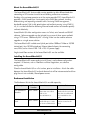
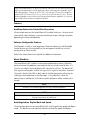
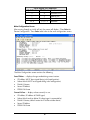
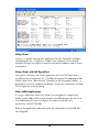
AccessEtherLinX/4
Operation Manual
FCC Radio Frequency Interference Statement
This equipment has been tested and found to comply with the limits for a Class B computing device, pursuant to Part 15 of the FCC Rules.
These limits are designed to provide reasonable protection against harmful interference when the equipment is operated in a commercial
environment. This equipment generates, uses and can radiate radio frequency energy and, if not installed and used in accordance with the
instruction manual, may cause harmful interference to radio communications. Operation of this equipment in a residential area is likely to
cause harmful interference in which the user will be required to correct the interference at his own expense.
Any changes or modifications not expressly approved by the manufacturer could void the user’s authority to operate the equipment.
The use of non-shielded I/O cables may not guarantee compliance with FCC RFI limits. This digital apparatus does not exceed the Class B
limits for radio noise emission from digital apparatus set out in the Radio Interference Regulation of the Canadian Department of
Communications.
Le présent appareil numérique n’émet pas de bruits radioélectriques dépassant les limites applicables aux appareils numériques de classe B
prescrites dans le Règlement sur le brouillage radioélectrique publié par le ministère des Communications du Canada.
Warranty
IMC Networks warrants to the original end-user purchaser that this product, EXCLUSIVE OF SOFTWARE, shall be free
from defects in materials and workmanship under normal and proper use in accordance with IMC Networks' instructions
and directions for a period of six (6) years after the original date of purchase. This warranty is subject to the limitations set
forth below.
At its option, IMC Networks will repair or replace at no charge the product which proves to be defective within such
warranty period. This limited warranty shall not apply if the IMC Networks product has been damaged by unreasonable
use, accident, negligence, service or modification by anyone other than an authorized IMC Networks Service Technician
or by any other causes unrelated to defective materials or workmanship. Any replaced or repaired products or parts carry
a ninety (90) day warranty or the remainder of the initial warranty period, whichever is longer.
To receive in-warranty service, the defective product must be received at IMC Networks no later than the end of the
warranty period. The product must be accompanied by proof of purchase, satisfactory to IMC Networks, denoting
product serial number and purchase date, a written description of the defect and a Return Merchandise Authorization
(RMA) number issued by IMC Networks. No products will be accepted by IMC Networks which do not have an RMA
number. For an RMA number, contact IMC Networks at PHONE: (800) 624-1070 (in the U.S and Canada) or (949) 4653000 or FAX: (949) 465-3020. The end-user shall return the defective product to IMC Networks, freight, customs and
handling charges prepaid. End-user agrees to accept all liability for loss of or damages to the returned product during
shipment. IMC Networks shall repair or replace the returned product, at its option, and return the repaired or new
product to the end-user, freight prepaid, via method to be determined by IMC Networks. IMC Networks shall not be
liable for any costs of procurement of substitute goods, loss of profits, or any incidental, consequential, and/or special
damages of any kind resulting from a breach of any applicable express or implied warranty, breach of any obligation
arising from breach of warranty, or otherwise with respect to the manufacture and sale of any IMC Networks product,
whether or not IMC Networks has been advised of the possibility of such loss or damage.
EXCEPT FOR THE EXPRESS WARRANTY SET FORTH ABOVE, IMC NETWORKS MAKES NO OTHER WARRANTIES,
WHETHER EXPRESS OR IMPLIED, WITH RESPECT TO THIS IMC NETWORKS PRODUCT, INCLUDING WITHOUT
LIMITATION ANY SOFTWARE ASSOCIATED OR INCLUDED. IMC NETWORKS SHALL DISREGARD AND NOT BE
BOUND BY ANY REPRESENTATIONS OR WARRANTIES MADE BY ANY OTHER PERSON, INCLUDING EMPLOYEES,
DISTRIBUTORS, RESELLERS OR DEALERS OF IMC NETWORKS, WHICH ARE
INCONSISTENT WITH THE WARRANTY SET FORTH ABOVE. ALL IMPLIED WARRANTIES INCLUDING THOSE OF
MERCHANTABILITY AND FITNESS FOR A PARTICULAR PURPOSE ARE HEREBY LIMITED TO THE DURATION OF THE
EXPRESS WARRANTY STATED ABOVE.
Every reasonable effort has been made to ensure that IMC Networks product manuals and promotional materials
accurately describe IMC Networks product specifications and capabilities at the time of publication. However, because of
ongoing improvements and updating of IMC Networks products, IMC Networks cannot guarantee the accuracy of printed
materials after the date of publication and disclaims liability for changes, errors or omissions.
ii
Table of Contents
FCC Radio Frequency Interference Statement ........................................................ ii
Warranty................................................................................................................ ii
About the AccessEtherLinX/4..................................................................................1
Installing the AccessEtherLinX/4..............................................................................1
Features .................................................................................................................2
About FiberAlert.....................................................................................................2
About iView²..........................................................................................................3
SNMP Management ...............................................................................................5
Configuring VLAN IDs ..........................................................................................11
UMA (Unified Management Agent) ......................................................................15
LED Operation.....................................................................................................19
Passwords ............................................................................................................20
Appendix .............................................................................................................21
Specifications .......................................................................................................22
IMC Networks Technical Support.........................................................................22
Fiber Optic Cleaning Guidelines...........................................................................23
Electrostatic Discharge Precautions.......................................................................23
Safety Certifications..............................................................................................24
iii
About the AccessEtherLinX/4
The AccessEtherLinX/4 Series enables service providers to offer differentiated data
networking or VPN services to multi-tenant building and business customers.
Residing at the customer premises or at the service provider POP, AccessEtherLinX/4
provides a VLAN-based Layer 2 entry point to the MAN fiber network, trunking,
differentiating and separating customer traffic. Featuring SNMP management,
bandwidth control, QoS, traffic prioritization and multicast pruning (using IGMP v1,
v2), it is an ideal solution for delivering Ethernet-based services to customers quickly
and cost-effectively.
AccessEtherLinX/4 offers configuration access via Telnet, serial console and SNMP
software. Software upgrades can be initiated via any one of these access methods
using a TFTP server. Additionally IMC’s iConfig/ iView² can be used for software
upgrades as a single source solution.
The AccessEtherLinX/4 includes one Uplink port (either 100Base-FX fiber or 10/100
twisted pair), four 10/100 twisted pair Ethernet downlink ports (for connecting
users/LANs) and an internal 100 - 240 ±10% AC power supply.
Single-strand fiber versions of the AccessEtherLinX/4 are also available.
Installing the AccessEtherLinX/4
The AccessEtherLinX/4 comes ready to install; there is no hardware configuration
required. All features, such as FiberAlert and Auto Negotiation, are software
configurable.
Place the AccessEtherLinX/4 on a flat surface, prior to installation. Attach the cables
between the AccessEtherLinX/4 and each device that will be interconnected and then
plug the unit into a reliable, filtered power source.
Rackmount Installation
The Rackmount kits for the AccessEtherLinX/4 are sold separately:
Description
19" Rackmount
brackets
19" Rackmount
shelf
Part
Number
895-39226
895-39949
Accessories
Includes two brackets
that screw onto either
side of the
AccessEtherLinX /4.
Fits into the 19" rack
and holds up to 3 units
of the AccessEtherLinX/4.
INSTALLATION TIP
1
Installation
The brackets are
attached to the unit and
then the AccessEtherLinX
/4 is installed into the
rack.
The AccessEtherLinX /4
can be secured to the
shelf.
Single-strand fiber products use optics that transmit and receive on two different wavelength.
Single-strand fiber products must be deployed in pairs, connecting two compatible singlestrand fiber products. Connect the 852-10133 (1310 xmt and 1550 rcv), for example, to a
product with 1550 xmt and 1310 rcv, e.g. 852-10134 (1550 xmt and 1310 rcv.) The two
connected products must also have the same speed and distance capabilities (i.e. both are
single-mode [20km] or both are single/PLUS [40km]).
Features
AutoCross Feature for Twisted Pair Connection
All twisted pair ports on the AccessEtherLinX/4 include AutoCross, a feature which
automatically selects between a crossover workstation or pass-through connection
depending on the connected device.
Software Configurable Features
The FiberAlert, as well as Auto Negotiation (Selective Advertising) and Bandwidth
Control features are all configurable via the management software or via serial
configuration or Telnet session.
Refer to the AccessEtherLinX/4 help file for additional information.
About FiberAlert
The AccessEtherLinX/4 includes an advanced troubleshooting feature, FiberAlert,
which minimizes the problems associated with the loss of one strand of fiber. If a
strand is unavailable, the AccessEtherLinX/4 notes the loss of link. The device will
then stop transmitting data and the link signal until a signal or link pulse is received.
The result is that the link LED on both sides of the fiber connection will extinguish,
indicating a fault somewhere in the fiber loop. Using FiberAlert, a local site
administrator is notified of a fault and can quickly determine where a cable fault is
located.
NOTE
FiberAlert is not available/applicable on single-strand fiber products.
NOTE
Enable FiberAlert on ONE side of a media conversion only; Enabling it on both sides would
keep both transmitters off indefinitely!
Auto Negotiation, Duplex Mode and Speed
The twisted pair ports on the AccessEtherLinX/4 Auto Negotiate for speed and duplex
mode. This device can also selectively advertise or force the speed and duplex
2
mode. If the device has a fiber Uplink port, it does not Auto Negotiate; it always
operates at 100 Mbps Full-Duplex.
Auto Negotiation
The AccessEtherLinX/4 ships with Auto Negotiation enabled on the twisted pair ports.
In this mode, the twisted pair port negotiates for speed and duplex mode.
Forcing the Speed and Duplex Mode
The twisted pair downlink ports on the AccessEtherLinX/4 can also be manually set
for 10 Mbps or 100 Mbps operation and for Half- or Full-Duplex (i.e. 10 Mbps FullDuplex, 10 Mbps Half-Duplex, 100 Mbps Full-Duplex or 100 Mbps Half- Duplex).
Selective Advertising
Selective Advertising, when used in combination with Auto Negotiation, advertises
only the configured speed and duplex mode for the twisted pair port.
If a specific speed and/or duplex mode is desired, use Selective Advertising, rather
than Force Mode, when connecting to devices that ONLY Auto Negotiate.
Bandwidth Control
The AccessEtherLinX/4 includes bandwidth control functionality. Bandwidth can be
set independently, in 32 Kbps increments, on each downlink port, or bandwidth can
be assigned to the entire unit via the uplink port. Refer to the help file for software
configuration information.
About iView²
iView² is a cross-platform network management application for intelligent networking
devices. It features a graphic user interface (GUI) and gives network managers the
ability to monitor and control devices from virtually any 32-bit Windows platform.
iView² can also function as a snap-in module for many SNMP applications. Refer to
the help files for iView² and AccessEtherLinX/4 for information regarding configuring
and managing the AccessEtherLinX/4.
About iConfig
iConfig is an in-band configuration utility that lets users quickly and easily complete
the first stages of SNMP configuration for SNMP-manageable devices. Tasks iConfig
can perform include:
3
•
•
Setting the IP address, subnet mask and default gateway
Defining the community strings and SNMP traps.
In addition to the above functions, iConfig offers an authorized IP address system and
access restriction to MIB groups supported by manageable devices. These extra
layers of security are purely optional and do not affect SNMP compatibility in any
way.
iConfig can be used to upload new versions of the system software and new MIB
information. It also offers diagnostic capabilities for faster resolution of technical
support issues. iConfig version 1.3 or above MUST be used for PROM updates.
HubControl32 and previous versions of iConfig will not work.
iConfig works with the following platforms:
•
•
•
•
Windows NT
Windows 2000
Windows XP
Windows Vista
iView² can be downloaded from the website: www:imcnetworks.com
4
SNMP Management
SNMP management and iConfig are available through the AccessEtherLinX/4 Uplink
port. This provides a higher level of security so end-users cannot access
management, alter settings, etc.
In order for the AccessEtherLinX/4 to allow for SNMP-management, the unit must be
assigned IP configuration information (e.g., IP address, subnet mask, etc.) There are
four ways to do so:
•
Using iConfig
•
Using the last Downlink port (port 4, depending on the model)
•
Using DHCP (Dynamic Host control Protocol); DHCP must be enabled
through the serial configuration or Telnet, via iConfig
•
Telnet (Default IP=10.10.10.10; subnet mask=255.0.0.0.
Configuring
In order for the AccessEtherLinX/4 to allow for SNMP-management, the unit must be
assigned IP configuration information (e.g., IP address, subnet mask, etc.) using
iConfig via iView²; the unit’s serial port or DHCP (Dynamic Host Control Protocol),
and Telnet. In addition to assigning an IP address and subnet mask, the former two
methods will also allow users to create community strings, assign access rights,
configure traps and more. However, iConfig offers more options than serial port
configuration.
After assigning an IP address, use iView² or another SNMP-compatible Network
Management System (NMS) to remotely configure, monitor and manage the
AccessEtherLinX/4.
About Serial Port Configuration
Use a DB-9 to RJ-45 cable to allow for serial port configuration on the Downlink Port
4 of the AccessEtherLinX/4. (See Appendix)
To connect the AccessEtherLinX to a terminal/computer, use a straight-through (pinto-pin) cable. (If the computer/terminal has a COM port using a connection not
compatible with a DB-9 connector, use the pin connection chart for reference in
making a cable.) Make sure the cable length is less than 50 feet (15.24m). Plug one
end of the cable into the DB-9 connector and the other into the appropriate
computer/terminal port. Set the computer/terminal for VT-100 emulation, with:
38.4K baud, 8 data bits, 1 stop bit, no parity and no flow control.
5
Serial Adapter Pin Connection
RJ-45 Pin #
DB-9 Pin # Function
5
2
Transmit (OUT)
7
3
Receive (IN)
8
5
Ground
1-4, 6
1, 4, 6 - 9 Reserved
Main Configuration Screen
After running through an initial self test, the screen will display: “Press Enter for
Device Configuration.” Press Enter to be taken to the main configuration screen.
The Main Configuration screen contains the following:
Saved Values — displays changes made during current session.
•
•
•
•
•
IP Address (MUST be assigned during initial configuration)
Subnet Mask (MUST be assigned during initial configuration)
Default Gateway
Server IP Address
PROM File Name
Current Values — displays values currently in use.
•
•
•
•
•
IP Address (IP address of SNMP agent)
Subnet Mask (mask to define IP subnet agent is connected to)
Default Gateway (default router for IP traffic outside subnet)
Server IP Address
PROM File Name
6
Command List
•
•
•
•
•
•
•
•
•
I = Enter New Saved Parameter Values
P = Change Password
T = New Trap Destination
K = Remove ALL Trap Destinations
C = New Community String
U = Delete ALL Community Strings
D = Enable/Disable DHCP
E = End Session
Space Bar = Opens device specific configuration options (tasks, memory,
cleandb, download, version, reboot, sysname, accounts, and
modules).
NOTE
Reboot after making any modifications to the Saved Values or the changes will not take
effect. To reboot, type Reboot at the prompt on the main configuration screen, or turn the
chassis power OFF then ON again.
Because a Delete key is not available on VT-100 terminal emulators, use the F2 key instead.
Assigning TCP/IP Information
To modify the Saved Parameter Values (i.e., assign IP address and subnet mask), press
I. Enter the IP address and subnet mask for the connected device, pressing Enter
after each value. A default gateway can also be assigned (press Enter to skip). When
finished, press Enter and then type Reboot for the changes to take effect. The Saved
Values and Current Values should now both display the changes made (e.g., new IP
address and subnet mask).
Change Serial Password
By default, no password is assigned via the serial port. However, one can be assigned
by pressing P from the main configuration screen. Enter a password; passwords are
case sensitive and should be no more than eight characters in length, with no spaces;
press Enter. This will be requested whenever logging on or off. To remove password
protection, select P and instead of entering a password press Enter.
Passwords are a way to make the management of network devices secure. It is the
responsibility of the network administrator to store and maintain the password lists.
Assigning Trap Destinations
Traps are sent by the manageable device to a management PC when a certain event
takes place. To enter a trap destination, press T. When asked to “Enter a New IP
Address.”, type the IP address of the destination device and press Enter. Then, type
the name of the community string (that the destination device has been configured to
7
Using iView²
iView² is a network management application for IMC Networks’ intelligent
networking devices. It features a Graphic User Interface (GUI) and gives
network managers the ability to monitor and control products from a variety
of platforms.
Using iView² with HP OpenView
During the installation, the iView² application will ask if HP OpenView is
installed on the management PC. Click Yes to integrate the appropriate files.
Within Open View, select the IMC Networks on the Navigation toolbar. A
drop down list of IMC Products will display, and can be individually selected
for management and monitoring.
Other NMS Applications
If using an application other than iView² for management, integrate the
SNMP vendor MIBs, which can be found in the MIB directory on the CD or
the subdirectory of iView² installed on the chosen hard drive of a
workstation: MCIMCV2c.MIB.
Refer to the application's documentation for information on how MIB files
are integrated.
14
Update Manager
iView² offers the option of scheduling an update search for IMC Networks’ devices
listed in the Network outline. Within iView², select Tools/SNMP Options from the
navigation toolbar. Select Update Manager Options, and a dialog box will be
displayed, in which you can select when to run the update search. This option
enables the end user to determine if they have the latest firmware, and download the
latest if they do not. It does not automatically run the download, so the end user can
review the release notes included with the binary file, and decide whether to
download it or not.
UMA (Unified Management Agent)
Centralized management makes practical sense for networks of all sizes,
especially service provider networks that must monitor and upgrade large
quantities of devices. The Unified Management Agent (UMA) allows
operators to manage all IMC modules with on-board logic (FiberLinX-II
series) installed in an IMC Networks iMediaChassis series, with a single IP
address from a central location. In addition, UMA allows users to centrally
manage and administer firmware upgrades over multiple devices.
Requirements:
•
iView² ver 1.8 or higher AccessEtherLinX/4 firmware ver C3 or higher
For example, install 20 iMcV-FiberLinX-II devices in a 20 slot iMediaChassis
at the Central Office (CO) then connect each to a remote AccessEtherLinX/4
unit installed at the customers premise (CPE); UMA will then allow users to
manage all 41 devices (including the chassis at the CO) via a single IP
address. Users may still assign IP addresses to each iMcV-FiberLinX-II and
AccessEtherLinX/4, and manage them independently.
With the Unified Management Agent
When an SNMP request for an iMcV-FiberLinX-II comes in, the SNMP
Management Module in the iMediaChassis series passes the request to the
SNMP agent in the specific module. The SNMP agent in the iMcVFiberLinX-II provides the relevant management information, which is then
routed via the SNMP Management Module and supplied to the client GUI,
as well as the serial port and Telnet.
File Management for Upgrading
The following screen, located in the iConfig utility of iView², shows the File
Management functionality of the Unified Management Agent. Operators can
15
easily upload and store new firmware versions for upgrading multiple devices
with on-board logic installed in, or connected to, an iMediaChassis series.
Using Telnet
Assign the AccessEtherLinX/4 an IP Address or use the default IP Address
10.10.10.10, subnet mask 255.0.0.0 before using a Telnet session. All configurations
done via the serial port can also be performed using Telnet. Use only one Telnet
session at a time. Do not use an RS-232 serial session and a Telnet session at the
same time.
Use Hyper Terminal to access the CLI (Command Line Interface). The manual will
describe how to do this.
Configuring the AccessEtherLinX/4 to Act as a Simple Media Converter
with a Switch
Use Hyper Terminal to access the CLI (Command Line Interface). The manual will
describe how to do this.
16
Press the Enter Key
Press the Space Bar
17
Type “dl_open” as shown above
Press Y to confirm this change
18
Press any key
Type reboot, and then press Enter to restart the system. When the system is done
rebooting it should work like a media converter with a 4-port switch attached.
LED Operation
Uplink and Downlink Ports
LNK/ACT
Glows green when link is established on port.
Blinks green during data activity on port.
FDX/COL
Glows amber when port is operating in Full-Duplex.
Blinks amber when collisions occur on port.
19
Passwords
Passwords are a way to make the management of network devices secure. If the
Serial password is lost, download the latest version of the binary file and load it
through the iConfig utility. Any serial password entered will be removed, and there
will be no password for the console session.
If the username/password are lost in iConfig, launch a Hyper Terminal session. Upon
completion of the boot sequence, press the Space Bar once and then type in the
command cleandb. This will reset the username/password back to admin/admin. If
BOTH password accesses are lost, contact Technical Support at 1-800-624-1070 for
information.
Before using iView²
iView² is a network management application designed for use on the IMC Networks
Intelligent Networking Devices. It features a Graphic User Interface (GUI) and gives
network managers the ability to monitor and control products from a variety of
platforms, iView² can also function as a snap-in module for HP Open View Network
Node Manager.
System Requirements
To run iView², the management PC must be equipped with the following:
• 29 MB free disk space, 64 MB RAM
• Windows: NT 4.0 Service Pack 5, 2000 Professional, or XP
• Microsoft SNMP Services Installed
• Microsoft IE 4.0 or Higher (not required as default browser)
• Microsoft IIS required for Web Server version
Java versions require the following:
•
•
•
25 MB free disk space, 64 MB RAM
Any OS capable of running Java (Windows 98 or above, Solaris, LINUX)
Java Runtime v 1.3
Strongly recommended:
•
•
•
128 MB RAM
Pentium III 650Mhz or Faster
17” Monitor @ 1024 x 768 Resolution or higher
Installing and Using iView²
Consult the iView² CD for installation information. The iView² help file provides
assistance in configuring/management IMC Networks’ modules.
20
When using iView² with HP OpenView
During the installation, the iView² application will ask if HP Open View is installed on
the management PC. Click Yes to integrate the appropriate files. Once in
OpenView, select IMC Networks from the toolbar to view the IMC Networks’
devices.
When Not Using iView²
When using an application other than iView² for management, integrate the SNMP
vendor files (a.k.a. MIBs) into the application. The SNMP agent uses the following
Enterprise-specific MIB file and standard MIBs, which can be found in the MIB
directory on the CD included with the iMediaChassis/3: MCIMCV2C.MIB Enterprise
specific information for the agent. For example, configuration information, port type
information, link status, etc.
Using the IMC MIBs
Refer to the MIBs folder located with the iView² software for product-related MIBs.
Appendix
The AccessEtherLinX/4 offers an optional method of configuring the device
via a Console session by connecting an RJ-45 to DB9 adapter. This adapter
is available for purchase through IMC Networks. End users can also wire
their own adapter using the schematic below.
21
Specifications
Operating Temperature
32° to 122° F (0° to 50° C)
Storage Temperature
-4° to 158° F (-20° to 70° C)
Humidity
5 to 95% (non-condensing)
Maximum heat generated
50 BTU/hr
Power Consumption (typical)
1.5 A @ 5 V
Throughput and VLAN Trunking
Up to full wire speed on all ports except the fourth (4/port) downlink port (this port
also functions as a serial port). In addition VLAN trunking is not available on the
fourth (4/port).
Dimensions
Height = 1.50” x Width = 4.75” x Depth = 7.25” (3.2 cm x 12.1 cm x 18.4 cm)
Weight = 1.6 lbs. (0.73 kg)
IMC Networks Technical Support
Tel: (949) 465-3000 or (800) 624-1070 (in the U.S. and Canada);
+32-16-550880 (Europe)
Fax: (949) 465-3020
E-Mail: [email protected]
Web: www.imcnetworks.com
22
Fiber Optic Cleaning Guidelines
Fiber Optic transmitters and receivers are extremely susceptible to contamination by
particles of dirt or dust, which can obstruct the optic path and cause performance
degradation. Good system performance requires clean optics and connector ferrules.
1.
Use fiber patch cords (or connectors, if you terminate your own fiber) only from
a reputable supplier; low-quality components can cause many hard-to-diagnose
problems in an installation.
2.
Dust caps are installed at IMC Networks to ensure factory-clean optical devices.
These protective caps should not be removed until the moment of connecting
the fiber cable to the device. Should it be necessary to disconnect the fiber
device, reinstall the protective dust caps.
3.
Store spare caps in a dust-free environment such as a sealed plastic bag or box
so that when reinstalled they do not introduce any contamination to the optics.
4.
If you suspect that the optics have been contaminated, alternate between
blasting with clean, dry, compressed air and flushing with methanol to remove
particles of dirt.
Electrostatic Discharge Precautions
Electrostatic discharge (ESD) can cause damage to any product, add-in modules or
stand alone units, containing electronic components. Always observe the following
precautions when installing or handling these kinds of products
1.
Do not remove unit from its protective packaging until ready to install.
2.
Wear an ESD wrist grounding strap before handling any module or component.
If the wrist strap is not available, maintain grounded contact with the system unit
throughout any procedure requiring ESD protection.
3.
Hold the units by the edges; do not touch the electronic components or gold
connectors.
4.
After removal, always place the boards on a grounded, static-free surface, ESD
pad or in a proper ESD bag. Do not slide the modules or stand alone units over
any surface.
WARNING! Integrated circuits and fiber optic components are
extremely susceptible to electrostatic discharge damage. Do not
handle these components directly unless you are a qualified service
technician and use tools and techniques that conform to accepted
industry practices.
23
Safety Certifications
UL/CUL: Listed to Safety of Information Technology Equipment, including
Electrical Business Equipment.
CE: The products described herein comply with the Council Directive on
Electromagnetic Compatibility (2004/108/EC) and the Council
Directive on Electrical Equipment Designed for use within Certain
Voltage Limits (2006/95/EC). Certified to Safety of Information
Technology Equipment, Including Electrical Business Equipment. For
further details, contact IMC Networks.
Class 1 Laser product, Luokan 1 Laserlaite,
Laser Klasse 1, Appareil A’Laser de Classe 1
European Directive 2002/96/EC (WEEE) requires that any equipment that bears this
symbol on product or packaging must not be disposed of with unsorted municipal
waste. This symbol indicates that the equipment should be disposed of separately
from regular household waste. It is the consumer’s responsibility to dispose of this
and all equipment so marked through designated collection facilities appointed by
government or local authorities. Following these steps through proper disposal and
recycling will help prevent potential negative consequences to the environment and
human health. For more detailed information about proper disposal, please contact
local authorities, waste disposal services, or the point of purchase for this equipment.
24
19772 Pauling • Foothill Ranch, CA 92610-2611 USA
TEL: (949) 465-3000 • FAX: (949) 465-3020
www.imcnetworks.com
© 2010 IMC Networks. All rights reserved.
The information in this document is subject to change without notice. IMC Networks assumes no responsibility for any
errors that may appear in this document. AccessEtherLinX/4 is a trademark of IMC Networks. Other brands or product
names may be trademarks and are the property of their respective companies.
Document Number 52-80120-00 C4
February 2010