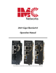
1
SNMP Management Module Operation Manual FCC Radio Frequency Interference Statement This equipment has been tested and found to comply with the limits for a Class B computing device, pursuant to Part 15 of the FCC Rules. These limits are designed to provide reasonable protection against harmful interference when the equipment is operated in a commercial environment. This equipment generates, uses and can radiate radio frequency energy and, if not installed and used in accordance with the instruction manual, may cause harmful interference to radio communications. Operation of this equipment in a residential area is likely to cause harmful interference in which the user will be required to correct the interference at his own expense. Any changes or modifications not expressly approved by the manufacturer could void the user’s authority to operate the equipment. The use of non-shielded I/O cables may not guarantee compliance with FCC RFI limits. This digital apparatus does not exceed the Class B limits for radio noise emission from digital apparatus set out in the Radio Interference Regulation of the Canadian Department of Communications. Le présent appareil numérique n’émet pas de bruits radioélectriques dépassant les limites applicables aux appareils numériques de classe B prescrites dans le Règlement sur le brouillage radioélectrique publié par le ministère des Communications du Canada. Warranty IMC Networks warrants to the original end-user purchaser that this product, EXCLUSIVE OF SOFTWARE, shall be free from defects in materials and workmanship under normal and proper use in accordance with IMC Networks' instructions and directions for a period of six (6) years after the original date of purchase. This warranty is subject to the limitations set forth below. At its option, IMC Networks will repair or replace at no charge the product which proves to be defective within such warranty period. This limited warranty shall not apply if the IMC Networks product has been damaged by unreasonable use, accident, negligence, service or modification by anyone other than an authorized IMC Networks Service Technician or by any other causes unrelated to defective materials or workmanship. Any replaced or repaired products or parts carry a ninety (90) day warranty or the remainder of the initial warranty period, whichever is longer. To receive in-warranty service, the defective product must be received at IMC Networks no later than the end of the warranty period. The product must be accompanied by proof of purchase, satisfactory to IMC Networks, denoting product serial number and purchase date, a written description of the defect and a Return Merchandise Authorization (RMA) number issued by IMC Networks. No products will be accepted by IMC Networks which do not have an RMA number. For an RMA number, contact IMC Networks at PHONE: (800) 624-1070 (in the U.S and Canada) or (949) 4653000 or FAX: (949) 465-3020. The end-user shall return the defective product to IMC Networks, freight, customs and handling charges prepaid. End-user agrees to accept all liability for loss of or damages to the returned product during shipment. IMC Networks shall repair or replace the returned product, at its option, and return the repaired or new product to the end-user, freight prepaid, via method to be determined by IMC Networks. IMC Networks shall not be liable for any costs of procurement of substitute goods, loss of profits, or any incidental, consequential, and/or special damages of any kind resulting from a breach of any applicable express or implied warranty, breach of any obligation arising from breach of warranty, or otherwise with respect to the manufacture and sale of any IMC Networks product, whether or not IMC Networks has been advised of the possibility of such loss or damage. EXCEPT FOR THE EXPRESS WARRANTY SET FORTH ABOVE, IMC NETWORKS MAKES NO OTHER WARRANTIES, WHETHER EXPRESS OR IMPLIED, WITH RESPECT TO THIS IMC NETWORKS PRODUCT, INCLUDING WITHOUT LIMITATION ANY SOFTWARE ASSOCIATED OR INCLUDED. IMC NETWORKS SHALL DISREGARD AND NOT BE BOUND BY ANY REPRESENTATIONS OR WARRANTIES MADE BY ANY OTHER PERSON, INCLUDING EMPLOYEES, DISTRIBUTORS, RESELLERS OR DEALERS OF IMC NETWORKS, WHICH ARE INCONSISTENT WITH THE WARRANTY SET FORTH ABOVE. ALL IMPLIED WARRANTIES INCLUDING THOSE OF MERCHANTABILITY AND FITNESS FOR A PARTICULAR PURPOSE ARE HEREBY LIMITED TO THE DURATION OF THE EXPRESS WARRANTY STATED ABOVE. Every reasonable effort has been made to ensure that IMC Networks product manuals and promotional materials accurately describe IMC Networks product specifications and capabilities at the time of publication. However, because of ongoing improvements and updating of IMC Networks products, IMC Networks cannot guarantee the accuracy of printed materials after the date of publication and disclaims liability for changes, errors or omissions. ii Table of Contents FCC Radio Frequency Interference Statement ........................................................ ii Warranty................................................................................................................ ii About the SNMP Management Module..................................................................1 Installing the Management Module ........................................................................1 Configuring ............................................................................................................2 SNMP Write Lock (iMediaChassis series) ................................................................3 Using the SNMP Write Lock Switch........................................................................4 Using Telnet...........................................................................................................5 About iConfig.........................................................................................................6 About Serial Port Configuration ..............................................................................7 UMA (Unified Management Agent) ......................................................................13 Passwords ............................................................................................................16 IMC Networks Technical Support.........................................................................17 Specifications .......................................................................................................17 Electrostatic Discharge Precautions.......................................................................18 Safety Certifications..............................................................................................19 iii About the SNMP Management Module The SNMP Management Module includes two twisted pair ports, one for management and one reserved for future use. The Management Module also features a DB-9 serial port. Both twisted pair ports include the AutoCross feature that automatically selects between a crossover workstation or straight-through, depending on the connected device. An iMediaChassis series with an installed Management Module connects to the LAN via an external 10/100 twisted pair connection. Connect the chassis to the network by plugging one end of a CAT-5 twisted pair cable into the port labeled MGMT on the Management Module. Plug the other end of the cable into a device (e.g., switch, hub, etc.) in the existing Ethernet network. Installing the Management Module In order to manage an iMediaChassis series, available in 20, 6, or 3 slots, install the SNMP Management Module. Slide the SNMP Management Module into the first slot, on the far left of the chassis, using the card guides, and secure the module to the chassis by tightening the captive screw. This slot is ONLY for the Management Module; do not install Application Modules such as media conversion and mode conversion modules in this slot. 1 SNMP Management Module LEDs Each SNMP Management Module features several LEDs. The LED functions are: Glows green when a link is established on port. LNK/ACT Glows green when data activity occurs. FDX/COL Blinks amber when port is in Full-Duplex mode. Blinks amber when collisions occur; extinguished when port is operating in Half-Duplex mode. TEMP Glows yellow when temperature of unit surpasses a user-defined Level, configurable through iView². PS Glows amber when one power supply malfunctions. FAN A / FAN B Refer to specific iMediaChassis series manuals for details Configuring Once connected to a network, assign the SNMP Management Module IP configuration information (e.g., IP address, subnet mask, etc.). There are four ways to do this: Using iConfig Using the Management Module’s serial port Using DHCP (Dynamic Host Control Protocol); DHCP must be enabled through serial configuration or Telnet, via iConfig Telnet (Default IP=10.10.10.10; subnet mask 255.0.0.0) In addition to assigning an IP address and subnet mask, the iMediaChassis series also allows creation of community strings, assigning access rights, configuration of traps and more. iConfig offers more options than configuring via the serial port or Telnet. After assigning the iMediaChassis series an IP address, use iView² or another SNMP compatible Network Management System (NMS) to remotely configure, monitor and manage the modules installed. 2 VLANS Modes IP Subnet Mask Default Gateway Bandwidth Software Updates TABLE: Configuration Options IView2 Serial Telnet 9 9 9 9 9 9 9 9 9 9 9 9 9 9 9 9 9 TFTP 9 9 TFTP iConfig 9 9 9 9 SNMP Write Lock (iMediaChassis series) There is an SNMP Write Lock switch on the iMediaChassis series; check the specific iMediaChassis manual for the location. The SNMP Write Lock switch prevents a new Management Module from re-configuring an iMcVapplication module’s settings (e.g. the status of features such as LinkLoss, FiberAlert, Force mode, etc.) made via SNMP on any previous management board (s). NOTE Leave this switch in the NORMAL position during day-to-day operation; the LOCKED position should only be used when changing the SNMP Management Module. As stated, SNMP Management Modules can be removed and replaced as necessary. A saved PROM file can be downloaded to the second SNMP module to retain configuration settings. Make sure the SNMP Write Lock switch is set to the LOCKED position. The PROM file should be saved periodically in case there is a need to replace the SNMP Management Module. Saving the existing PROM creates a back-up file which can be used in the event that a unit or PROM update fails. It is recommended that the PROM be saved after the user is satisfied with his current configuration settings, as saving the PROM at this point will allow them to recover their configurations as well. 3 1. Open a session in iConfig with a device you want to administer. 2. Choose the Administration tab. 3. Click the Save PROM File button. 4. The Save as PROM dialog box appears. 5. Choose a folder and then select the filename you wish to save. NOTE .BIN is the default extension. 6. Click the Save button to save, the file is saved. 7. Add entries to the Notes box, if desired; then click OK. If you do not wish to enter Notes, click Close. 8. Click OK to close Succeeded dialog box. (Prom Save was successful.) If the Management Module is removed with the SNMP Write Lock switch set to NORMAL, all module revert to their hardware settings by default; for any module with on-board logic, refer to its manual for details. Hardware settings should be configured to match those made via SNMP. Always reconfigure application modules when moving them from one chassis’ slot to another. Using the SNMP Write Lock Switch 1. Ensure the SNMP Write Lock switch is set to NORMAL. 2. After configuring all application module settings via SNMP, use the iConfig application to make a backup copy of the SNMP management board’s firmware. 3. If the SNMP Management Module needs to be replaced, set the SNMP Write Lock switch to LOCKED. 4. Remove the old SNMP module and replace with another SNMP module. 5. Connect to this SNMP module via iView² and then launch iConfig. Select the Administration tab and click on List Tasks. Highlight Flashsav and then click on the Terminate button. 6. Update the new board with the firmware backup made in Step 2. 7. Reboot the SNMP Management Module with the reboot command to enable changes. 4 8. After rebooting, set the SNMP Write Lock switch back to NORMAL. The previously made settings to the application modules will be active. NOTE When removing an SNMP card with the SNMP Write Lock enabled (set to LOCKED), current application modules settings will not be changed. Never power-cycle the chassis while the SNMP Write Lock is enabled (except during Step 5 in the preceding process). This will revert the SNMP card back to its original factory settings. (iView² should only be accessed with the SNMP Write Lock disabled.) Using Telnet The iMediaChassis series supports Telnet for remote configuration. All configurations that can be performed via the serial port can also be performed using Telnet (except serial passwords). Use only one Telnet session at a time. Do not use an RS-232 serial session and a Telnet session at the same time. About DHCP DHCP Disable (Static IP Addressing) DHCP is disabled in the default configuration. Initially, modules are assigned a Static default IP Address of 10.10.10.10. Changes to the Static IP Address can be added manually through iConfig, an RS-232 Serial session, or Telnet. The changes will be initiated following reboot of the module DHCP Enable (Dynamic IP Addressing) If a DHCP server is present on the network and DHCP is enabled, the DHCP client will initiate a dialog with the server during the boot up sequence. The server will then issue an IP address to the management card. Once the new IP address is received, the SNMP Management Module will reboot so that the new IP address will take effect. Refer to the About Serial Port Configuration for more information about Enabling/Disabling DHCP. When there is no DHCP server on the network, use iConfig or serial configuration to manually set the IP addresses. When DHCP is enabled, the IP address (default 10.10.10.10 or user configured) is saved. When DHCP is disabled, the saved IP address will be reinstated and the device will reboot. DHCP servers give out lease times: devices renew their leases based on the administrator-specified time. If a device cannot renew its lease, and the lease expires, the device will be given the IP address 10.10.10.10 and will reboot. 5 About iConfig iConfig is an in-band configuration utility (in iView²) that lets users quickly and easily complete the first stages of SNMP configuration for SNMPmanageable devices. iConfig can set the IP address, subnet mask and default gateway as well as define the community strings and SNMP traps. In addition to the above functions, iConfig offers an authorized IP address system and access restriction to MIB groups supported by manageable devices. These extra layers of security are purely optional and do not affect SNMP compatibility. The iConfig utility can be used to upload new versions of the system software and new MIB information. It also offers diagnostic capabilities for faster resolution of technical support issues. The default user ID for both iConfig and Telnet is: User: admin / Password: admin The three levels of Telnet account access are: User Can only see status, change password and reboot Operator Can perform User functions and change settings Administrator Can perform all functions and add/delete accounts and perform the command cleandb A Username and Password can be added in the USER tab of iConfig, or the Accounts command within Telnet or the Serial Configuration. Admin/admin should not be deleted until new usernames/passwords are tested. See page 16 for additional information. The iConfig utility works with the following platforms: • • • • Windows 98 Windows NT Windows 2000 Windows XP The iConfig utility is available as a standalone application, as well as built in to the Windows version of iView² (Windows 98 users must use the standalone version of the iConfig utility). Both applications are included on 6 the iView² CD. For information regarding the use of the iConfig utility, refer to the iConfig utility help file. About Serial Port Configuration The SNMP Management Modules used with the iMediaChassis series feature a serial port that includes a DB-9 serial connector. To connect an iMediaChassis series to a terminal/computer, use a straight-through (pin-topin) cable. If the computer/terminal’s port is not compatible with a DB-9 COM port, use the pin connection chart for reference in making a cable.) Make sure the cable length is less than 50 feet (15.24 meters). Plug one end of the cable into the DB-9 connector and the other into the appropriate port on the computer/terminal. Set the computer/terminal for VT-100 emulation. The serial port on the computer/terminal should be set for: 38.4K baud, 8 data bits, 1 stop bit, no parity, no flow control. The F2 key functions as a Delete key on VT-100 emulators. Serial Adapter Pin Connection RJ-45 Pin # DB-9 Pin # Function 5 2 Transmit (OUT) 7 3 Receive (IN) 8 5 Ground 1-4, 6 1, 4, 6 - 9 Reserved Main Serial/Telnet Configuration Screen After running through an initial self-test, the screen will display the following message: "Press Enter for Device Configuration." Press Enter for the main configuration screen, which includes the following displays: 7 Saved Values This section displays changes made during current session: • IP Address (MUST be assigned during initial configuration) • Subnet Mask (MUST be assigned during initial configuration) • Default Gateway Current Values This section displays values currently in use: • IP Address (IP address of SNMP agent) • Subnet Mask (mask to define IP subnet agent is connected to) • Default Gateway (default router for IP traffic outside subnet) Command List This section displays the commands available: • I = Enter New Saved Parameter Values • P = Change Password • T = New Trap Destination • K = Remove ALL Trap Destinations • C = New Community String • U = Delete ALL Community Strings • D = Enable/Disable DHCP • E = End Session • Space Bar = Device Specific Configuration commands NOTE Reboot after making any modifications to the saved parameter values or the changes will not take effect. To reboot, type REBOOT at the prompt on the main configuration screen, or turn the chassis OFF then ON again by turning off the switches on the back of the power supplies, or reseat the module. Assigning TCP/IP Information To modify the saved parameter values (i.e., assign IP address and subnet mask), press I. Enter the IP address and subnet mask for the connected 8 device, pressing Enter after each. The default gateway can also be assigned, if desired (press Enter to skip). When finished, press Enter, then type reboot for changes to take effect. The Saved Values and Current Values should now display both the changes made (e.g., new IP address and subnet mask). Creating Community Strings for SNMP The purpose of community strings is to add a level of security to a network. The default community string is named "public" and has read/write access. Do not delete the community string “public” until the new community string has been tested. Add necessary custom community strings such as one with read/only access (for general use), the other with read/write access (for the administrator). To create a new community string, go to the main configuration screen and press C. Enter the name of the new community (up to 16 characters, no spaces) and press Enter. Then type one of the following to assign the community string's access rights: R = read-only access W = read/write access Enter = abort Press Enter. When finished, press Enter, and type reboot for changes to take effect. The Saved Values and Current Values should now both display the changes made (e.g., new IP address and subnet mask). iConfig MIB definitions allow the user greater control of Community Strings than serial or telnet. Deleting Community Strings To delete all community strings (except the default, “public”) and start over, press U. Press Y to delete all strings or N to abort. Then, press Enter. This function will delete ALL community strings. To selectively delete community strings, use iConfig. Assigning Trap Destinations A manageable device sends traps when a certain events take place. To enter a trap destination, press T. Enter the IP address of the destination device and press Enter. Then, type the name of the community string (that the destination device has been configured to accept) and press Enter. This 9 function enables ALL of the traps. To selectively activate and deactivate traps, use iConfig. iConfig Traps allow greater control using the Trap Edit than the serial and Telnet does. To choose generic or enterprise-specific Traps, use iConfig. Removing Trap Destinations To remove all trap destinations, press K. Press Y to remove all trap destinations. Press N to abort and then press Enter. Change Serial Password The serial configuration does not have a default password; it is optional. Password protect the serial configuration process by pressing P from the main configuration screen. Type the password and press Enter. Passwords are case sensitive and should be no more than eight characters in length, with no spaces. This password will be requested whenever logging on or off. To remove password protection, select P and instead of entering a password, press Enter. Enabling/Disabling DHCP To Enable/Disable DHCP, press D and then type reboot for the changes to take effect. Refer to page 5 for more information. Ending a Session When ending a session, press E before disconnecting the cable in order to stop the device from continuing to send feedback status through to the serial port. If a session is not ended properly, the Telnet session cannot be launched. Device-Specific Options— Downloading Files With the iMediaChassis series, firmware can be downloaded from a central server via a TFTP protocol. Initiate this download via serial configuration or Telnet session. Make sure the IP Address and the name of the file being downloaded are correct in the Current Values section of the Main Configuration screen. To download a file, press the Space Bar in the Command List section of the Main Configuration screen (serial configuration). Type download and press Enter to be taken to the Download a File screen. This screen displays the IP Address of the TFTP server and the name of the file. Press Enter to start downloading the file. 10 If the download is interrupted, do not reset the module or reboot the SNMP Management Module; doing so can corrupt the PROM and render the module useless. Close the session and then open a new TFTP session. Additional Device-Specific Options The iMediaChassis series also includes device-specific options. Press the Space Bar when in the Command List section of the Main Configuration screen (serial configuration/Telnet session), type the name of the action, and press Enter. tasks Displays the task list with priorities. memory Displays the memory usage cleandb Removes all information in the database, except the IP address of the device. download Opens the Download dialog box where the firmware is located and can be downloaded via the server address. The Server IP Addr must be entered in the Main Configuation screen using TFTP protocol. version Displays the PROM version and build date reboot Reboots the unit sysdescr Allows the editing of sysName, sysDescr, and Port information text. accounts Allows management of Usernames/Passwords account. Administrators must maintain a password list. modules Displays a list of installed modules including the slot location. 11 Downloading Files Refer to Device-Specific Options— Downloading Files. Using iView² iView² is a network management application for IMC Networks’ intelligent networking devices. It features a graphic user interface (GUI) and gives network managers the ability to monitor and control products from a variety of platforms. Using iView² with HP OpenView During the installation, the iView² application will ask if HP OpenView is installed on the management PC. Click Yes to integrate the appropriate files. Once in OpenView, highlight the media converter icon and select the media converter; OpenView will then launch iView². Other NMS Applications If using an application other than iView² for management, integrate the SNMP vendor MIBs, which can be found in the MIB directory on the CD or the subdirectory of iView² installed on the chosen hard drive of a workstation: MCIMCV2c.MIB. Refer to the application's documentation for information on how MIB files are integrated. Update Manager iView² offers the option of scheduling an update search for IMC Networks’ devices listed in the Network outline. Within iView², select Tools/SNMP Options from the navigation toolbar. Select Update Manager Options, and a dialog box will be displayed, in which you can select when to run the update search. This option enables the end user to determine if they have the latest firmware, and download the latest if they do not. It does not automatically run the download, so the end user can review the release notes included with the binary file, and decide whether to download it or not. 12 UMA (Unified Management Agent) Centralized management makes practical sense for networks of all sizes, especially service provider networks that must monitor and upgrade large quantities of devices. The Unified Management Agent (UMA) allows operators to manage all IMC modules with on-board logic (FiberLinX-II series) installed in an IMC Networks iMediaChassis series, with a single IP address from a central location. In addition, UMA allows users to centrally manage and administer firmware upgrades over multiple devices. For example, install 20 iMcV-FiberLinX-II devices in a 20 slot iMediaChassis at the Central Office (CO) then connect each to a remote iMcV-FiberLinX-II unit installed at the customers premise (CPE); UMA will then allow users to manage all 41 devices (including the chassis at the CO) via a single IP address. Users may still assign IP addresses to each iMcV-FiberLinX-II and manage them independently when the SNMP Management Module within the iMediaChassis is omitted. With the Unified Management Agent When an SNMP request for an iMcV-FiberLinX-II comes in, the SNMP Management Module in the iMediaChassis series passes the request to the SNMP agent in the specific module. The SNMP agent in the iMcVFiberLinX-II provides the relevant management information, which is then routed via the SNMP Management Module and supplied to the client GUI (iView², version 1.8 or higher), as well as the serial port and Telnet. 13 Easy Upgrades with the Unified Management Agent • Upgrade one or multiple Host (CO) or Remote (CPE) devices with just a few mouse clicks. Refer to the iMcV-FiberLinX-II, iMcV-GigaFiberLinX, AccessEtherLinX and IE-Mini FiberLinX-II series manuals for complete information. • All devices in chassis are fully functional while upgrades are in process. • Manage up to 41 devices with a single IP address. • Telnet access and view for all system devices. • Only one Ethernet port is required, reducing the number of ports used on a network switch. File Management for Upgrading The following screen, located in the iConfig utility of iView², shows the File Management functionality of the Unified Management Agent. Operators can easily upload and store new firmware versions for upgrading multiple devices with on-board logic installed in, or connected to, an iMediaChassis series. 14 Telnet Session With the Unified Management Agent, users can also manage multiple devices installed in, or connected to, an iMediaChassis via a Telnet session, as well as assigning an IP address. In the example below, the devices listed on the left (e.g. MetroFiber 3 represent Host iMcV-FiberLinX-II units while the devices listed on the right (Irvine POP 3) represent Remote iMcV-FiberLinX-II units. The names (SNMP sysName) given to each iMcV-FiberLinX-II device are easily assigned/ changed via iView², serial configuration, etc.). The FiberLinX-II series modules offer a new mode of saving a Configuration File, as well as a Restore File option. Please refer to the appropriate manuals for complete information. 15 System Requirements To run iView², the management PC must be equipped with the following: • 29 MB free disk space, 64 MB RAM • Windows NT 4.0 Service Pack 5, 2000 Professional, XP Professional • Microsoft SNMP Services Installed • Microsoft IE 4.0 or Higher • Microsoft IIS required for Web Server Version Java versions require the following: • 25 MB free disk space, 64 MB RAM • Any OS capable of running Java (Windows 98 or above, Solaris, LINUX) • Java Runtime v 1.3 (Standalone) • Java Runtime v 1.2 (Servlet) Strongly recommended: • 128 MB RAM Minimum • Pentium III 650Mhz or Faster, or Pentium IV with 512MB RAM • 17" Monitor @ 1024 x 768 Resolution or higher Please consult the iView² CD for installation information. The Help tab in iView² provides assistance in configuring/managing modules. Passwords Passwords are a way to make the management of network devices secure. If the Serial password is lost, download the latest version of the binary file and load it through the iConfig utility. Any serial password entered will be removed, and there will be no password for the console session. If the username/password are lost in iConfig, launch a HyperTerminal session to access the CLI. Once the boot sequence is complete, press the Spacebar and then type in the command cleandb. This will reset the username/password back to admin/admin. If BOTH password accesses are lost, contact Technical Support at 1-800-624-1070 for information. 16 IMC Networks Technical Support Tel: (949) 465-3000 or (800) 624-1070 (in the U.S. and Canada); +32-16-550880 (Europe) Fax: (949) 465-3020 E-Mail: [email protected] Web: www.imcnetworks.com Specifications Environmental: Operating Temperature 32° - 104° F (0° - 40° C) Storage Temperature 21° - 160° F (-6° - 71° C) Humidity 5 - 95% (non-condensing) 17 Electrostatic Discharge Precautions Electrostatic discharge (ESD) can cause damage to your add-in modules. Always observe the following precautions when installing or handling an add-in module or any board assembly. 1. Do not remove unit from its protective packaging until you’re ready to install it. 2. Wear an ESD wrist grounding strap before handling any module or component. If you do not have a wrist strap, maintain grounded contact with the system unit throughout any procedure requiring ESD protection. 3. Hold boards by the edges only; do not touch the electronic components or gold connectors. 4. After removal, always place the boards on a grounded, static-free surface, ESD pad or in a proper ESD bag. Do not slide the board over any surface. WARNING! Integrated circuits and fiber optic components are extremely susceptible to electrostatic discharge damage. Do not handle these components directly unless you are a qualified service technician and use tools and techniques that conform to accepted industry practices. 18 Safety Certifications UL/CUL: Listed to Safety of Information Technology Equipment, including Electrical Business Equipment. CE: The products described herein comply with the Council Directive on Electromagnetic Compatibility (89/336/EEC) and the Council Directive on Electrical Equipment Designed for use within Certain Voltage Limits (73/23/EEC). Certified to Safety of Information Technology Equipment, Including Electrical Business Equipment. For further details, contact IMC Networks. European Directive 2002/96/EC (WEEE) requires that any equipment that bears this symbol on product or packaging must not be disposed of with unsorted municipal waste. This symbol indicates that the equipment should be disposed of separately from regular household waste. It is the consumer’s responsibility to dispose of this and all equipment so marked through designated collection facilities appointed by government or local authorities. Following these steps through proper disposal and recycling will help prevent potential negative consequences to the environment and human health. For more detailed information about proper disposal, please contact local authorities, waste disposal services, or the point of purchase for this equipment. 19 Notes 20 19772 Pauling • Foothill Ranch, CA 92610-2611 USA TEL: (949) 465-3000 • FAX: (949) 465-3020 www.imcnetworks.com © 2008 IMC Networks. All rights reserved. The information in this document is subject to change without notice. IMC Networks assumes no responsibility for any errors that may appear in this document. IE-MediaChassis/2 is a trademark of IMC Networks. Other brands or product names may be trademarks and are the property of their respective companies. Document Number 50-80950-01 A0 July 2008 If the product’s part number begins with an “8”, it is compliant with the Restriction of Hazardous Substances (RoHS) directive.