1
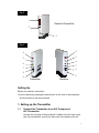
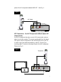
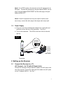
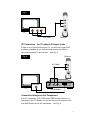
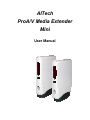
AITech
ProA/V Media Extender
Mini
User Manual
Package Contents
• Transmitter x 1
• Receiver x 1
• Infrared (IR) eye cable x 1
• Remote antenna x 1
• Audio/Video cable x 2
• Power adaptors (DC6V) x 2
• User manual x 1
Note: The transmitter and the receiver look very similar. You can find
“transmitter” and “receiver” labels on the side of the units. See Fig. 1.
Fig. 1
Receiver
Transmitter
Receiver
Transmitter
Product Layout
Transmitter/Receiver (See Fig. 2 and Fig. 3)
1. Power/Channel Indicator
2. IR Window
3. Channel Select Button (Select the channel by pressing the tact switch to
the channel number you want. Select the same channel both on the
transmitter and the receiver).
4. Audio Jack (Red)
5. Audio Jack (White)
6. Video Jack (Yellow)
7. Power On/Off
8. Power Adaptor Plug
9. IR Eye (Transmitter) / Antenna(Receiver)
1
Fig. 2
1
Receiver/Transmitter
2
3
Fig. 3
4
4
5
5
6
6
7
7
8
8
9
9
Transmitter
Receiver
Setting Up
Before you make the connection:
• Set the channel by pressing the select button on the front of the transmitter
and the receiver to the same channel.
1. Setting up the Transmitter
1.1
Connect the Transmitter to an A/V Component
A/V Connection
Connect the mini-plug of the provided A/V cables to the A/V jack on the
rear of the transmitter; connect the other end of the cables to the A/V
2
jacks of the A/V component labeled LINE OUT. See Fig. 4.
Fig. 4
A/V Cable
OUT
VIDEO
AUDIO
Transmitter
Satellite receiver/DVD/VCD
RF Connection – for A/V Component without Spare A/V
Output Jacks
If your A/V component has only one set of A/V output jacks, and you
want to use it with a nearby TV, connect coaxial cable from the signal
OUT port on the A/V component to the VHF/UHF IN port on your TV.
In order to also view cable transmission on that TV, connect your
incoming cable TV source to the single IN port of the A/V component.
Please see Fig. 5.
Fig. 5
Transmitter
RF OUT
VHF/UHF
VIDEO
TV
AUDIO
IN
A/V Component
3
Note 1: On a NTSC system, the connector on the A/V equipment is an
RCA jack. Connect the yellow plug to the jack labeled VIDEO, the red
plug to the jack labeled AUDIO RIGHT and the white plug to the jack
labeled AUDIO LEFT.
Note 2: If the A/V equipment has only one output for audio (mono
sound only), connect the white plug to that single audio output jack.
1.2
Power Supply
a. Plug one end of the provided power adaptor into a wall outlet and
the other end into the rear of the transmitter. See Fig. 6.
b. Turn on the transmitter.
light up.
The LED on the front of the unit should
Fig. 6
POW ER
ON-OFF
Wall Outlet
Transmitter
2. Setting up the Receiver
2.1
Connect the Receiver to a TV
A/V Connect – for TV with A/V Input Jacks
Connect the mini-plug of the provided A/V cables to the A/V jack on the
rear of the receiver; connect the other end of the cable to the A/V jacks
on the TV labeled LINE IN. See Fig. 7.
4
Fig. 7
VIDEO AUDIO IN
TV
A/V Cable
Receiver
RF Connection – for TV without A/V Input Jacks
If there is no A/V input jacks on your TV, you will need to get an RF
modulator (available at your local electronics store) to make the
connection between TV and receiver. See Fig. 8.
Fig. 8
Receiver
A/V Cable
VHF/UHF
VIDEO
TV
AUDIO
IN
CH 3/4
RF OUT
RF Modulator
Connection through an A/V Component
If an A/V component (VCR, DVD player, DBS receiver, and etc.) is
connected to the TV already, you can just connect the receiver to the
free LINE IN jacks on the A/V component. See Fig. 9.
5
Fig. 9
Receiver
A/V Cable
RF OUT
VHF/UHF
VIDEO
TV
AUDIO
IN
A/V Component
Note 1: Connect the yellow plug to the jack labeled VIDEO, the red plug
to the jack labeled AUDIO RIGHT and the white plug to the jack labeled
AUDIO LEFT.
Note 2: If the TV has only one input for audio (mono sound only),
connect the white plug to that single audio in jack.
2.2
Connecting the Remote Antenna
a. Connect the provided remote antenna with the receiver by plugging
it in the hole labeled Ant. on the receiver.
b. If possible, make the antenna straight. Do not bend the antenna.
See Fig. 10.
Fig. 10
Receiver
2.3
Remote Antenna
Power Supply
a. Plug one end of the provided power adaptor into a wall outlet and
6
the other end into the rear of the receiver. See Fig. 11.
b. Turn on the receiver.
up.
The LED on the front of the unit should light
Fig. 11
POW ER
ON-OFF
Wall Outlet
Receiver
Other Applications
Using Remote Control
The Wireless A/V Sender gives you the ability to control A/V components from
another room using your existing remote control device. To use this function,
follow the steps below:
1. Place the transmitter next/close to the A/V source component and plug the
IR eye into the jack located on the rear of the transmitter (IR Eye plug).
Adhere the IR eye directly to the IR window on the front of the source
component (see Fig. 12) OR place the IR eye in front of the source
component (see Fig. 13).
AV Source
Component
Fig. 12
Transmitter
IR Eye
TV
Receiver
Fig. 13
Remote Control
AV Source
Component
7
Transmitter
IR Eye
TV
Receiver
Remote Control
2. Position the receiver so that your remote control signal can strike the IR
window on the front of the receiver. Set the remote antenna on the
receiver straight. Do not bend the remote antenna.
3. To use your remote control, point it at the front of the receiver and operate it
as you normally would.
Specifications
Transmitter/Receiver
A/V Transmitting Frequency
IR Extender Frequency
2.4GHz
433.92MHz
A/V Signal Range
IR Extender Range
Antenna
100 meters (300 feet) clear line of sight
70 meters (200 feet) clear line of sight
Built-in antenna
Channel
4 selectable channels
Audio
Video
Stereo audio input and output
Composite input and output
Dimensions
Weight
12.5 x 8 x 2.5 (cm) for transmitter/receiver
125g for transmitter/receiver
Power
DC6V, 500mA
Operating Temperature
0C ~ 40C (32F ~ 104F)
Providing the latest technologies to our customers is our responsibility;
therefore, we reserve the right to change the specifications without prior notice.
8
Trouble Shooting
If you are not getting any signal at all
• Check that the transmitter and receiver are properly connected to the A/V
components from which you want to send/receive the A/V signal.
• Make sure the transmitter and the receiver are turned on.
• Check power switches on the remote TV and video source (VCR, DVD
player, satellite receiver, etc).
• Make sure power plugs are pushed all the way in.
• Check all cable connections.
• Check the CHANNEL switch on both transmitter and receiver are set to the
same number.
• If you connect the receiver to a TV through an RF modulator, check that the
TV is tuned to the same channel as the TV Channel switch on the RF
modulator (3 or 4).
If the signal is poor, or there is interference
• Adjust the transmitter by rotating orientations until you get the best reception.
• Change the channel on both transmitter and receiver and make them the
same.
• If there is a microwave oven in use in the path between the transmitter and
receiver, remove the microwave oven or turn it off.
• Make sure the transmitter and receiver are within range of each other (range
of approximately 300 feet; 100 meters in a clear line of sight).
Care and Maintenance
• Keep all its parts and accessories out of the reach of young children.
• Do not attempt to open the case. Non-expert handling of the device may
damage it.
• Keep dry. Precipitation, humidity, and liquids, contain minerals that will
corrode electronic circuits.
• Do not use or store in dusty, dirty areas. Moving parts may be damaged.
• Do not store in hot areas. High temperatures can shorten the life of
electronic devices and warp or melt certain plastics.
• Do not store in very cold areas. When the A/V sender warms up (to its
normal temperature), moisture can form inside the case, which may damage
electronic circuit boards.
9
• Do not drop, knock, or shake it. Rough handling can break internal circuit
boards.
• Do not use harsh chemicals, cleaning solvents, or strong detergents when
cleaning.
• Operate this product using only the power supply included with it.
• Do not overload electrical outlets or extension cords as this can result in fire
or electric shock.
FCC Label Compliance Statement:
This device complies with Part 15 of the FCC Rules. Operation is subject to the
following two conditions: (1) this device may not cause harmful interference,
and (2) this device must accept any interference received, including
interference that may cause undesired operation.
Note: The manufacturer is not responsible for any radio or TV interference
caused by unauthorized modifications to this equipment. Such modifications
could void the user's authority to operate the equipment.
10