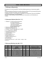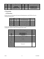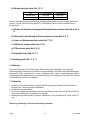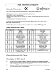
1
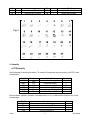
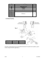
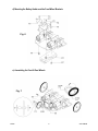
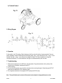
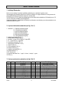
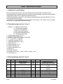
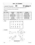
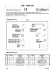
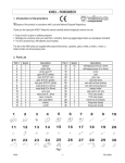
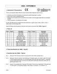
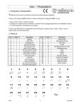
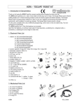
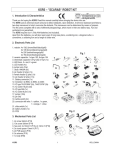
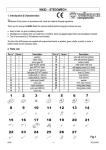
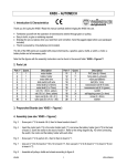
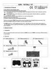
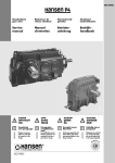
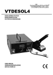
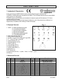
KSR2 – ROBOT FROG
1. Introduction & Characteristics
Thank you for buying the KSR2 ! Read this manual carefully before bringing the device into use.
The KSR2 is a robot frog that uses a microphone as a detector. The car changes directions when the sensor detects
noise or when the car hits an object.
The KSR2 requires one 9V DC battery (not included) for the electronic parts and 2 AA-batteries of 1.5V for the
mechanical parts (not included).
Apart from the batteries, you will also need a length of solder wire, a pair of long-nose pliers, a soldering iron, a
diagonal cutter, a screwdriver and a soldering iron stand with sponge.
Fig. 1
2. Electronic Parts List
1. resistor : 2 x 100Ω (brown/black/brown/gold)
2 x 4.7K (yellow/violet/red/gold)
1 x 10K (brown/black/orange/gold)
1 x 22K (red/red/orange/gold)
5 x 33K (orange/orange/orange/gold)
2 x 2.7M (red/violet/green/gold)
2. battery snap with wires 15cm (1 x)
3. battery holder with wires 8cm (1 x)
4. transistor : 2 x type 1815 (or C945) and 2 x type 8050
5. IC : 1 x type 4017 and 1 x type 406P
6. ceramic capacitor 47P (1 x)
7. electrolytic capacitor 1uf (2 x)
8. diode IN 4148 (6 x)
9. mylar capacitor 103 (1 x)
10. microphone Ø10mm (1 x)
11. variable resistor 200K (1 x)
12. slide switch (1 x)
13. Ø1.3mm pin (8 x)
14. connector with wire 15cm : 1 x yellow, 1 x blue, 1 x orange, 1 x green
15. PCB (1 x)
3. Mechanical Parts List
Part n°
1
2
3
4
5
6
7
8
9
10
11
KSR2
Quant.
2
2
2
2
2
2
2
2
2
4
2
Description
gearbox
motor DC3V
metal shaft (2 x 40mm)
metal shaft (3 x 52mm)
pinion gear 10T (white)
face gear 36T/14T (white)
gear 36T/0T (white)
gear 36T/14T (red)
gear 36T/14T (green)
nylon pad (5.6 x 4.8 x 1.95mm)
rear wheel (Ø32 x 3.5mm)
Part n°
15
16
17
18
19
20
21
22
23
24
25
1
Quant.
1
2
1
1
1
1
2
5
2
1
6
Description
battery holder (9V-battery)
hex post (M3 x 25mm)
right front wheel bracket
left front wheel bracket
nylon post (Ø3 x 3mm)
nylon nut
nut M3
nut M2
washer (3.2 x 10 x 0.5mm)
self-tapping screw (2 x 4mm)
screw (M3 x 8mm)
VELLEMAN
12
13
14
2
1
1
rubber tyre
front wheel (Ø20mm)
rubber ring (Ø15 x 2.5mm)
26
27
28
1
5
1
screw (M3 x 16mm)
screw (M2 x 10mm)
wooden plate (included)
Fig. 2
4. Assembly
a) PCB Assembly
Start the assembly by mounting the resistors. The names of all components have been printed on the PCB. Consult
the table below :
Part ID
R10/13
R8/11
R1
R7
R2/4/6/9/12
R3/5
Description.
100Ω
4.7K
10K
22K
33K
2.7M
Colour Code
brown/black/brown/gold
yellow/violet/red/gold
brown/black/orange/gold
red/red/orange/gold
orange/orange/orange/gold
red/violet/green/gold
Quantity
2
2
1
1
5
2
Mount the diodes, capacitors, transistors, the variable resistor, the IC’s, the slide switch and the pins next. Consult
the table below :
Part ID
D1/2/3/4/5/6
C2
C1
C3/4
KSR2
Description
diodes IN 4148
ceramic capacitor 47P
mylar capacitor 103
electrolytic capacitor 1uf
2
Quant.
6
1
1
2
VELLEMAN
Q2/4
Q1/3
VR
MIC
IC1
IC2
SW
ML + MR + 3V +
9V +
G
transistor 8050
transistor 1815 (or C945)
variable resistor 100K
microphone
IC 4069
IC 4017
slide switch
2
2
1
1
1
1
1
Ø1.3mm pin
8
b) Gearbox Assembly
left gearbox
after assembly
right gearbox
after assembly
Fig. 3
Part ID
right gearbox
left gearbox
Motor’s “+” Pole
yellow wire
orange wire
Motor’s “-” Pole
blue wire
green wire
Note that the protruding edge should be pointed towards the metal case. The yellow wire is the positive (+) pole of
the motor, the green wire is the negative pole (-).
KSR2
3
VELLEMAN
c) Mounting the Gearboxes onto the Wooden Plate & Mounting the Hex Posts
Fig. 4
Fig. 5
KSR2
4
VELLEMAN
d) Mounting the Battery Holder and the Front Wheel Brackets
Fig. 6
e) Assembling the Front & Rear Wheels
Fig. 7
KSR2
5
VELLEMAN
f) Inserting the AA-Batteries
Fig. 8
g) Assembling the PCB
A
MR+
B
MR-
C
ML+
D
ML-
yellow
blue
green
orange
E
3V
+
red
F
G
black
3V
G
9V
+
red
H
G
black
3V
Fig. 9
KSR2
6
VELLEMAN
h) Finished Product
Fig. 10
5. Wiring Diagram
Fig. 11
6. Operation
Put the switch in the “ON”-position. Place the device on the floor and verify whether it moves smoothly. Clap your
hands repeatedly to make the KSR2 execute the following steps : stop → move forward to the left → stop → move
forward to the right → stop → move forward in a straight line. Adjust “VR” with a screwdriver to change the
microphone’s sensitivity. Turn the screwdriver to the right for increased sensitivity and vice versa.
7. Troubleshooting
1. Make sure all components on the PCB are in the right position. Pay particular attention to the polarity of the
microphone, the transistors, capacitors and the IC’s.
2. Check the wiring.
3. The noise from the gearbox may prevent the microphone from receiving the signal. Grease face gear 36T/14T
(white) and the metal shaft (n°3) to reduce the noise.
4. Do not grease metal shaft (n°4) and gears 36T/0T (white) and 36T/14T (red).
Note : The specifications and contents of this manual can be subject to change without prior notice.
KSR2
7
VELLEMAN
KSR2 – ROBOTKIKKER
1. Inleiding & Kenmerken
Dank u voor uw aankoop ! Lees deze handleiding aandachtig voor u het toestel in gebruik neemt.
Deze stemgestuurde robotkikker gebruikt een microfoon als detector. De wagen verandert van richting wanneer de
sensor lawaai detecteert of wanneer de wagen een voorwerp raakt.
De KSR2 werkt op 1 9V DC batterij (niet meegeleverd) voor de elektronische onderdelen en 2 AA-batterijen van 1.5V
voor de mechanische onderdelen (niet meegeleverd).
Andere benodigdheden : soldeerdraad, een bektang, een soldeerijzer, een zijkniptang, een schroevendraaier en een
soldeerbouthouder met spons.
2. Lijst van elektronische onderdelen (zie fig. 1 blz. 1)
1. weerstand : 2 x 100Ω (bruin/zwart/bruin/goud)
2 x 4.7K (geel/paars/rood/goud)
1 x 10K (bruin/zwart/oranje/goud)
1 x 22K (rood/rood/oranje/goud)
5 x 33K (oranje/oranje/oranje/goud)
2 x 2.7M (rood/paars/groen/goud)
2. batterijclip met draden 15cm (1 x)
3. batterijhouder met draden 8cm (1 x)
4. transistor : 2 x type 1815 (of C945) en 2 x type 8050
5. IC : 1 x type 4017 en 1 x type 406P
6. keramische condensator 47P (1 x)
7. elektrolytische condensator 1uf (2 x)
8. diode IN 4148 (6 x)
9. mylar condensator 103 (1 x)
10. microfoon Ø10mm (1 x)
11. regelbare weerstand 200K (1 x)
12. schuifschakelaar (1 x)
13. Ø1.3mm pin (8 x)
14. connector met draad 15cm : 1 x geel, 1 x blauw, 1 x oranje, 1 x groen
15. PCB (1 x)
3. Lijst van mechanische onderdelen (zie fig. 2 blz. 2)
Nr.
1
2
3
4
5
6
7
8
9
10
KSR2
Hoev.
2
2
2
2
2
2
2
2
2
4
Beschrijving
tandwielkast
motor DC3V
metalen as (2 x 40mm)
metalen as (3 x 52mm)
rondsel 10T (wit)
tandwiel 36T/14T (wit)
tandwiel 36T/0T (wit)
tandwiel 36T/14T (rood)
tandwiel 36T/14T (groen)
nylon kraagring (5.6 x 4.8 x
Nr.
15
16
17
18
19
20
21
22
23
24
8
Hoev.
1
2
1
1
1
1
2
5
2
1
Beschrijving
batterijhouder (9V-batterij)
hexag. afstandsbus (M3 x 25mm)
montagebeugel achterwiel rechts
montagebeugel achterwiel links
nylon ring (Ø3 x 3mm)
nylon moer
M3 moer
M2 moer
borgring (3.2 x 10 x 0.5mm)
zelftappende schroef (2 x 4mm)
VELLEMAN
11
12
13
14
2
2
1
1
1.95mm)
achterwiel (Ø32 x 3.5mm)
rubberen band
voorwiel (Ø20mm)
rubberen band (Ø15 x 2.5mm)
25
26
27
28
6
1
5
1
schroef (M3 x 8mm)
schroef (M3 x 16mm)
schroef (M2 x 10mm)
houten plaatje (meegeleverd)
4. Montage
a) Montage van de PCB
Monteer eerst de weerstanden. De namen van alle componenten staan op de PCB. Raadpleeg de tabel hieronder :
Onderdeel
R10/13
R8/11
R1
R7
R2/4/6/9/12
R3/5
Beschrijving.
100Ω
4.7K
10K
22K
33K
2.7M
Kleurcode
bruin/zwart/bruin/goud
geel/paars/rood/goud
bruin/zwart/oranje/goud
rood/rood/oranje/goud
oranje/oranje/oranje/goud
rood/paars/groen/goud
Hoeveelheid
2
2
1
1
5
2
Monteer de diodes, de condensatoren, de transistors, de regelbare weerstand, de IC’s, de schuifschakelaar en de
pennen. Bekijk de tabel hieronder :
Onderdeel
D1/2/3/4/5/6
C2
C1
C3/4
Q2/4
Q1/3
VR
MIC
IC1
IC2
SW
ML + MR + 3V +
9V +
G
KSR2
Beschrijving
diodes IN 4148
keramische condensator 47P
mylar condensator 103
elektrolytische condensator 1uf
transistor 8050
transistor 1815 (or C945)
regelbare weerstand 100K
microfoon
IC 4069
IC 4017
schuifschakelaar
Hoev.
6
1
1
2
2
2
1
1
1
1
1
Ø1.3mm pin
8
9
VELLEMAN
b) Tandwielkasten assembleren (zie fig. 3 op blz. 3)
Onderdeel
tandwielkast rechts
tandwielkast links
“+” pool van motor
gele draad
oranje draad
“-” pool van motor
blauwe draad
groene draad
Merk op dat de uitstekende rand naar de metalen behuizing moet worden gericht. De gele draad is de positieve (+)
pool van de motor, de groene draad is de negatieve (-) pool. Bovenaan de figuur ziet u de afgewerkte tandwielkasten
na montage.
c) Tandwielkasten monteren op de houten plaat en hexagonale afstandsbussen monteren
(zie fig. 4 & 5 op blz. 4)
d) Batterijhouder en montagebeugels voor voorwiel monteren (zie fig. 6 op blz. 5)
e) Voorwiel en achterwielen monteren (zie fig. 7 op blz. 5)
f) AA-batterijen inbrengen (zie fig. 8 op blz. 6)
g) PCB monteren (zie fig. 9 op blz. 6)
h) Afgewerkt product (zie fig. 10 op blz. 7)
5. Bedrading (zie fig. 11 op blz. 7)
6. Bediening
Stel de schakelaar in de “ON”-stand. Plaats de KSR2 op de grond en ga na of het toestel vlot beweegt. Klap in uw
handen voor elke nieuwe beweging. De KSR2 voert achtereenvolgens deze bewegingen uit : stop → vooruit links →
stop → vooruit rechts → stop → voorwaarts in een rechte lijn. Pas de gevoeligheid van de microfoon aan met een
schroevendraaier (“VR”-regeling). Draai naar rechts om de gevoeligheid te verhogen en omgekeerd.
7. Problemen en oplossingen
1. Ga na of alle componenten op de PCB op de juiste plaats zitten. Besteed de nodige aandacht aan de polariteit
van de microfoon, de transistors en de condensatoren.
2. Controleer de bedrading.
3. Het lawaai van de tandwielkast kan de microfoon hinderen bij de detectie van het signaal. Smeer tandwiel
36T/14T (wit) en de metalen as (n°3) om het lawaai te verminderen.
4. Volgende onderdelen mag u NIET smeren : metalen as (n°4) en tandwielen 36T/0T (wit) en 36T/14T (rood)
Opmerking : De inhoud en de specificaties van deze handleiding kunnen worden gewijzigd zonder
voorafgaande kennisgeving.
KSR2
10
VELLEMAN
KSR2 – GRENOUILLE ROBOT
1. Introduction & caractéristiques
Nous vous remercions de votre achat ! Lisez le manuel attentivement avant de prendre votre KSR2 en service.
Cette grenouille robot à commande vocale utilise un microphone en tant que détecteur. La grenouille change de direction
quand le détecteur capte un bruit ou quand la grenouille touche un objet.
La KSR2 est alimentée par une pile 9V CC (non incluse) pour pièces électroniques et deux piles LR6 (AA) de 1.5V pour
les pièces mécaniques (non incluses).
A part des piles, vous aurez également besoin de fil d’apport, une pince plate, un fer à souder, une pince coupante,
un tournevis et un support de fer à souder avec éponge.
2. Pièces électroniques (voir fig. 1 à la p. 1)
1. résistance : 2 x 100Ω (brun/noir/brun/doré)
2 x 4.7K (jaune/violet/rouge/doré)
1 x 10K (brun/noir/orange/doré)
1 x 22K (rouge/rouge/orange/doré)
5 x 33K (orange/orange/orange/doré)
2 x 2.7M (rouge/violet/vert/doré)
2. contact à pression avec fils 15cm (1 x)
3. support de pile avec fils 8cm (1 x)
4. transistor : 2 x type 1815 (ou C945) et 2 x type 8050
5. CI : 1 x type 4017 et 1 x type 406P
6. condensateur céramique 47P (1 x)
7. condensateur électrolytique 1uf (2 x)
8. diode IN 4148 (6 x)
9. condensateur mylar 103 (1 x)
10. microphone Ø10mm (1 x)
11. résistance réglable 200K (1 x)
12. glissière (1 x)
13. broche Ø1.3mm (8 x)
14. connecteur avec fil 15cm : 1 x jaune, 1 x bleu, 1 x orange, 1 x vert
15. circuit imprimé (1 x)
3. Pièces mécaniques (voir fig. 2 à la p. 2)
Pièce
1
2
3
Quant.
2
2
2
Description
boîte d’engrenages
moteur CC3V
axe métallique (2 x 40mm)
Pièce
15
16
17
Quant.
1
2
1
4
2
axe métallique (3 x 52mm)
18
1
5
6
7
8
9
2
2
2
2
2
satellite 10T (blanc)
pignon 36T/14T (blanc)
pignon 36T/0T (blanc)
pignon 36T/14T (rouge)
pignon 36T/14T (vert)
19
20
21
22
23
1
1
2
5
2
KSR2
11
Description
support de pile (pile 9V)
entretoise hexag. (M3 x 25mm)
support de montage roue arrière
(droite)
support de montage roué arrière
(gauche)
embout en nylon (Ø3 x 3mm)
écrou en nylon
écrou M3
écrou M2
rondelle de serrage (3.2 x 10 x
VELLEMAN
10
4
11
12
13
14
2
2
1
1
canon en nylon (5.6 x 4.8 x
1.95mm)
roué arrière (Ø32 x 3.5mm)
pneu en caoutchouc
roué avant (Ø20mm)
pneu en caoutchouc (Ø15 x
2.5mm)
24
1
0.5mm)
vis taraudeuse (2 x 4mm)
25
26
27
28
6
1
5
1
écrou (M3 x 8mm)
écrou (M3 x 16mm)
écrou (M2 x 10mm)
plaque en bois (incluse)
4. Montage
a) Montage du circuit imprimé
Montez d’abord les résistances. Les noms des composants sont imprimés sur le circuit. Consultez la table cidessous :
Pièce
R10/13
R8/11
R1
R7
R2/4/6/9/12
R3/5
Description
100Ω
4.7K
10K
22K
33K
2.7M
Couleur
brun/noir/brun/doré
jaune/violet/rouge/doré
brun/noir/orange/doré
rouge/rouge/orange/doré
orange/orange/orange/doré
rouge/violet/vert/doré
Quantité
2
2
1
1
5
2
Montez les diodes, les condensateurs, les transistors, la résistance réglable (VR), les CI, la glissière et les broches.
Consultez la table ci-dessous :
Pièce
D1/2/3/4/5/6
C2
C1
C3/4
Q2/4
Q1/3
VR
MIC
IC1
IC2
SW
ML + MR + 3V +
9V +
G
KSR2
Description
diodes IN 4148
condensateur céramique47P
condensateur mylar 103
condensateur électrolytique 1uf
transistor 8050
transistor 1815 (ou C945)
résistance réglable 100K
microphone
IC 4069
IC 4017
glissière
Quant.
6
1
1
2
2
2
1
1
1
1
1
Ø1.3mm pin
8
12
VELLEMAN
b) Assemblage des boîtes d’engrenages (voir fig. 3 à la p. 3)
Pièce
boîte d’engrenages droite
boîte d’engrenages gauche
Pôle “+” du moteur
fil jaune
fil orange
Pôle “-” du moteur
fil bleu
fil vert
Remarquez que la protubérance doit indiquer le boîtier métallique. Le fil jaune est le pôle positif (+) du moteur, le fil
vert est le pôle négatif (-). En haut de la figure vous voyez les boîtes d’engrenages après montage.
c) Montage des boîtes d’engrenages sur la plaque en bois & montage des entretoises
hexagonales (voir fig. 4 & 5 à la p. 4)
d) Montage du support de pile et des supports de la roue avant (voir fig. 6 à la p. 5)
e) Montage de la roue avant et de la roue arrière (voir fig. 7 à la p. 5)
f) Insérer les piles LR6 (AA) (voir fig. 8 à la p. 6)
g) Montage du circuit imprimé (voir fig. 9 à la p. 6)
h) Produit fini (voir fig. 10 à la p. 7)
5. Câblage (voir fig. 11 à la p. 7)
6. Opération
Placez la glissière dans la position “ON”. Posez la KSR2 par terre et vérifiez si l’appareil bouge comme il faut. La
KSR2 exécutera les pas suivants si vous battez des mains après chaque manœuvre : la KSR2 s’arrête → avance
vers la gauche → s’arrête → avance vers la droite → s’arrête → mouvement tout droit et en avant. Ajustez la
sensibilité du microphone avec un tournevis (réglage “VR”). Tournez à droite pour augmenter la sensibilité et vice
versa
7. Problèmes et solutions
1. Vérifiez si chaque composant du CI est à sa propre place. Prêtez une attention spéciale à la polarité du
microphone, des transistors et des condensateurs.
2. Contrôlez le câblage.
3. Le bruit de la boîte d’engrenages peut empêcher la détection du signal par le microphone. Graissez pignon
36T/14T (blanc) et l’axe métallique (n°3) pour diminuer le bruit.
4. Ne graissez pas les pièces suivantes : l’axe métallique (n°4) et les pignons 36T/0T (blanc) et 36T/14T (rouge)
Remarque : Le contenu et les spécifications de cette notice peuvent être modifiées sans notification
préalable.
KSR2
13
VELLEMAN
KSR2 – RANA ROBOT
1. Introducción y Características
¡Gracias por haber comprado la KSR2 ! Lea cuidadosamente las instrucciones del manual antes de montarla.
Esta rana activada por voz use un micrófono como detector. Cambia de dirección si el detector detecta un ruido o si el
aparato se choca contra un objeto.
La KSR2 funciona con una pila de 9V DC (no incluida) para las piezas electrónicas y dos pilas AA de 1.5V para las piezas
mecánicas (no incluidas).
Necesitará también hilo de estaño, alicates de punta plana larga, un soldador, unos alicates de corte en diagonal, un
destornillador y un soporte de soldador con esponja.
2. Piezas electrónicas (véase fig. 1 en la p. 1)
1. resistencia : 2 x 100Ω (marrón /negro/marrón/dorado)
2 x 4.7K (amarillo/violeta/rojo/dorado)
1 x 10K (marrón/negro/naranja/dorado)
1 x 22K (rojo/rojo/naranja/dorado)
5 x 33K (naranja/naranja/naranja/dorado)
2 x 2.7M (rojo/violeta/verde/dorado)
2. clip para pila con hilos 15cm (1 x)
3. portapilas con hilos 8cm (1 x)
4. transistor : 2 x tipo 1815 (o C945) y 2 x tipo 8050
5. CI : 1 x tipo 4017 y 1 x tipo 406P
6. condensador cerámico 47P (1 x)
7. condensador electrolítico 1uf (2 x)
8. diodo IN 4148 (6 x)
9. condensador mylar 103 (1 x)
10. micrófono Ø10mm (1 x)
11. resistencia regulable 200K (1 x)
12. conmutador deslizante (1 x)
13. polo Ø1.3mm (8 x)
14. conector con hilo 15cm : 1 x amarillo, 1 x azul, 1 x naranja, 1 x verde
15. circuito impreso (1 x)
3. Piezas mecánicas (véase fig. 2 en la p. 2)
Cantidad
1
2
3
Pieza
2
2
2
Descripción
caja de engranajes
motor CC3V
eje metálico (2 x 40mm)
Cantidad
15
16
17
Pieza
1
2
1
4
2
eje metálico (3 x 52mm)
18
1
5
6
7
8
9
2
2
2
2
2
satélite 10T (blanco)
piñón 36T/14T (blanco)
piñón 36T/0T (blanco)
piñón 36T/14T (rojo)
piñón 36T/14T (verde)
19
20
21
22
23
1
1
2
5
2
KSR2
14
Descripción
portapilas (pila de 9V)
separador hexag. (M3 x 25mm)
soporte de montaje rueda trasera
(derecha)
soporte de montaje rueda trasera
(izquierda)
anillo de nylon (Ø3 x 3mm)
tuerca de nylon
tuerca M3
tuerca M2
arandela de ajuste (3.2 x 10 x
VELLEMAN
10
4
11
12
13
14
2
2
1
1
cañón de nylon (5.6 x 4.8 x
1.95mm)
rueda trasera (Ø32 x 3.5mm)
rueda de goma
rueda delantera (Ø20mm)
rueda de goma (Ø15 x
2.5mm)
24
1
0.5mm)
tornillo autoroscante (2 x 4mm)
25
26
27
28
6
1
5
1
tornillo (M3 x 8mm)
tornillo (M3 x 16mm)
tornillo (M2 x 10mm)
panel de madera (incluido)
4. Montaje
a) Montaje del circuito impreso
Monte las resistencias cuyos nombres están impresos en el CI. Consulte la siguiente lista :
Pieza
R10/13
R8/11
R1
R7
R2/4/6/9/12
R3/5
Descripción
100Ω
4.7K
10K
22K
33K
2.7M
Color
marrón/negro/marrón/dorado
amarillo/violeta/rojo/dorado
marrón/negro/naranja/dorado
rojo/rojo/naranja/dorado
naranja/naranja/naranja/dorado
rojo/violeta/verde/dorado
Cantidad
2
2
1
1
5
2
Monte los diodos, los condensadores, los transistores, la resistencia regulable (VR), los CI, el conmutador deslizante
y los polos. Consulte la siguiente lista :
Pieza
D1/2/3/4/5/6
C2
C1
C3/4
Q2/4
Q1/3
VR
MIC
IC1
IC2
SW
ML + MR + 3V +
9V +
G
KSR2
Descripción
diodos IN 4148
condensador cerámico 47P
condensador mylar 103
condensador electrolítico 1uf
transistor 8050
transistor 1815 (o C945)
resistencia regulable 100K
micrófono
IC 4069
IC 4017
conmutador deslizante
Cantidad
6
1
1
1
2
2
1
1
1
1
1
polo Ø1.3mm
8
15
VELLEMAN
b) Montaje de las cajas de engranajes (véase fig. 3 en la p. 3)
Pieza
caja de engranajes derecha
caja de engranajes
izquierda
polo “+” del motor
hilo amarillo
hilo naranja
polo “-” del motor
hilo azul
hilo verde
Preste atención a que el saliente apunte hacia la caja metálica. El hilo amarillo es el polo positivo (+), el hilo verde el
polo negativo (-). En la parte superior de la figura ve las cajas de engranajes después del montaje.
c) Montaje de las cajas de engranajes en el panel de madera & montaje de los separadores
hexagonales (véase fig. 4 & 5 en la p. 4)
d) Montaje del portapilas y de los soportes de la rueda delantera (véase fig. 6 en la p. 5)
e) Montaje de la rueda delantera y de la rueda trasera (véase fig. 7 en la p. 5)
f) Introducir las pilas AA (véase fig. 8 en la p. 6)
g) Montaje del circuito impreso (véase fig. 9 en la p. 6)
h) Producto acabado (véase fig. 10 en la p. 7)
5. Cableado (véase fig. 11 en la p. 7)
6. Funcionamiento
Coloque el conmutador deslizante en la posición “ON”. Ponga la KSR2 en el suelo y verifique si el aparato mueve
correctamente. Dando palmadas después de cada maniobra la KSR2 debería hacer los siguientes pasos : la KSR2
se para → avanza hacia la izquierda → se para → avanza hacia la derecha → se para → sigue todo recto. Ajuste
la sensibilidad del micrófono mediante un destornillador (reglaje “VR”). Gire a la derecha para aumentar la
sensibilidad y viceversa
7. Solución a problemas
1. Verifique si cada componente del CI se encuentra en la buena posición. Atención a la polaridad del micrófono,
los transistores y los condensadores.
2. Compruebe el cableado.
3. El ruido de la caja de engranajes puede impedir la detección de la señal por el micrófono. Engrase el piñón
36T/14T (blanco) y el eje metálico (n°3) para disminuir el ruido.
4. No engrase las piezas siguientes : el eje metálico (n°4) y los piñones 36T/0T (blanco) y 36T/14T (rojo)
Observación : Se pueden modificar las especificaciones y el contenido de este manual sin previo aviso.
KSR2
16
VELLEMAN
KSR2 – ROBOTERFROSCH
1. Einführung und Eigenschaften
Wir bedanken uns für den Kauf des KSR2 ! Lesen Sie diese Bedienungsanleitung vor Inbetriebnahme sorgfältig
durch.
Dieses Sprachgesteuertes Roboterfrosch verwendet ein Mikrofon als Detektor. Der Frosch ändert die Richtung wenn
der Sensor Lärm erfasst oder wenn der Frosch einen Gegenstand berührt.
Der Bausatz funktioniert mit 1 9V DC-Batterie (nicht mitgeliefert) für die elektronischen Teile und mit 2 AA-Batterien
von 1.5V für die mechanischen Teile (nicht mitgeliefert).
Erforderlich : Lötdraht, Spitzzange, Lötkolben, Seitenschneider, Schraubendreher und Lötkolbenständer mit
Schwamm.
2. Elektronische Stückliste (Siehe Abb. 1, S. 1)
1. Widerstand : 2 x 100Ω (braun/schwarz/braun/gold)
2 x 4.7K (gelb/violett/rot/gold)
1 x 10K (braun/ schwarz/orange/gold)
1 x 22K (rot/rot/orange/gold)
5 x 33K (orange/orange/orange/gold)
2 x 2.7M (rot/violett/grün/gold)
2. Batterieclip mit Drähten 15cm (1 x)
3. Batteriehalter mit Drähten 8cm (1 x)
4. Transistor : 2 x Typ 1815 (oder C945) und 2 x Typ 8050
5. IC : 1 x Typ 4017 und 1 x Typ 406P
6. keramischer Kondensator 47P (1 x)
7. Elektrolytkondensator 1uf (2 x)
8. Diode IN 4148 (6 x)
9. Mylar-Kondensator 103 (1 x)
10. Mikrophon Ø10mm (1 x)
11. regelbarer Widerstand 200K (1 x)
12.Schiebeschalter (1 x)
13. Ø1.3mm-Pol (8 x)
14. Anschluss mit Draht 15cm : 1 x gelb, 1 x blau, 1 x orange, 1 x grün
15. PCB (1 x)
3. Mechanische Stückliste (siehe Abb. 2, S. 2)
Nr.
1
2
3
4
5
6
7
8
9
KSR2
Anzahl
2
2
2
2
2
2
2
2
2
Beschreibung
Getriebe
Motor DC3V
Metallachse (2 x 40mm)
Metallachse (3 x 52mm)
Ritzel 10T (weiß)
Zahnrad 36T/14T (weiß)
Zahnrad 36T/0T (weiß)
Zahnrad 36T/14T (rot)
Zahnrad 36T/14T (grün)
Nr.
15
16
17
18
19
20
21
22
23
17
Anzahl
1
2
1
1
1
1
2
5
2
Beschreibung
Batteriehalter (9V-Batterie)
hexag. Distanzbuchse (M3 x 25mm)
Halterung für Hinterrad rechts
Halterung für Hinterrad links
Nylonring (Ø3 x 3mm)
Nylonmutter
Mutter M3
Mutter M2
Unterlegscheibe (3.2 x 10 x 0.5mm)
VELLEMAN
10
11
12
13
14
4
2
2
1
1
Nylonbuchse (5.6 x 4.8 x 1.95mm)
Hinterrad (Ø32 x 3.5mm)
Gummireifen
Vorderrad (Ø20mm)
Gummireifen (Ø15 x 2.5mm)
24
25
26
27
28
1
6
1
5
1
Schneidschraube (2 x 4mm)
Schraube (M3 x 8mm)
Schraube (M3 x 16mm)
Schraube (M2 x 10mm)
Holzplatte (mitgeliefert)
4. Zusammenbau
a) PCB montieren
Montieren Sie zuerst die Widerstände. Die Namen aller Widerstände stehen auf der PCB-Platte. Ziehen Sie
nachfolgende Tabelle zu Rate :
Teil
R10/13
R8/11
R1
R7
R2/4/6/9/12
R3/5
Beschreibung
100Ω
4.7K
10K
22K
33K
2.7M
Farbe
braun/schwarz/braun/gold
gelb/violett/rot/gold
braun/schwarz/orange/gold
rot/rot/orange/gold
orange/orange/orange/gold
rot/violett/grün/gold
Anzahl
2
2
1
1
5
2
Montieren Sie die Dioden, die Kondensatoren, die Transistoren, den regelbaren Widerstand, die ICs, den
Schiebeschalter und die Pole. Ziehen Sie nachfolgende Tabelle zu Rate :
Teil
D1/2/3/4/5/6
C2
C1
C3/4
Q2/4
Q1/3
VR
MIC
IC1
IC2
SW
ML + MR + 3V +
9V +
G
KSR2
Beschreibung
Dioden IN 4148
keramischer Kondensator 47P
Mylar-Kondensator 103
Elektrolytkondensator 1uf
Transistor 8050
Transistor 1815 (oder C945)
regelbarer Widerstand 100K
Mikrophon
IC 4069
IC 4017
Schiebeschalter
Anzahl
6
1
1
2
2
2
1
1
1
1
1
Ø1.3mm Pol
8
18
VELLEMAN
b) Getriebe montieren (siehe Abb. 3, S. 3)
Teil
Getriebe rechts
Getriebe links
“+” -Pol des Motors
Draht, gelb
Draht, orange
“-”-Pol des Motors
Draht, blau
Draht, grün
Beachten Sie, dass der herausragende Rand auf das Metallgehäuse gerichtet sein muss. Der gelbe Draht ist der
positive (+) Pol, der grüne Draht ist der negative Pol (-).Auf Abbildung 4 können Sie die Transmissionen nach
Montage sehen
c) Getriebe auf Holzplatte und hexagonale Distanzbuchsen montieren (siehe Abb.4 & 5, S.
4)
d) Batteriehalter und Halterung für Vorderrad montieren (siehe Abb. 6, S. 5)
e) Vorder- und Hinterrad montieren (siehe Abb. 7, S. 5)
f) AA-Batterien einlegen (siehe Abb. 8, S. 6)
g) PCB montieren (siehe Abb. 9, S. 6)
h) Endprodukt (siehe Abb. 10, S. 7)
5. Verdrahtung (siehe Abb. 11, S. 7)
6. Bedienung
Stellen Sie den Schalter auf “ON”. Stellen Sie den KSR2 auf den Boden und überprüfen Sie ob das Gerät
geschmeidig bewegt. Klatschen Sie in die Hände für jede neue Bewegung. Der KSR2 macht folgende Bewegungen
nacheinander : Stopp → geradeaus links → stopp → geradeaus rechts → Stopp → vorwärts geradeaus. Passen
Sie die Empfindlichkeit des Mikrophons mit einem Schraubendreher (“VR”-Regelung) an. Drehen Sie nach rechts um
die Empfindlichkeit zu erhöhen und umgekehrt.
7. Fehlersuche
1. Kontrollieren Sie ob alle Komponenten richtig auf dem PCB montiert wurden. Beachten Sie die Polarität des
Mikrophons, der Transistoren und der Kondensatoren.
2. Kontrollieren Sie die Verdrahtung.
3. Der Lärm des Getriebes kann das Mikrophon bei der Signalerfassung hindern. Schmieren Sie Zahnrad 36T/14T
(weiß) und die Metallachse (n°3) um den Lärm zu verringern.
4. Nachfolgende Teile dürfen Sie NICHT schmieren : Metallachse (n°4) und Zahnräder 36T/0T (weiß) und 36T/14T
(rot)
Bemerkung : Änderungen in Technik und Ausstattung vorbehalten
KSR2
19
VELLEMAN