1
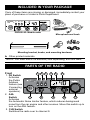
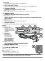
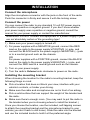
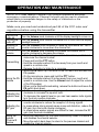
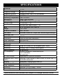
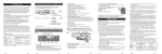
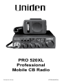
PRO 520XL
Professional
Mobile CB Radio
Printed in China.
UTZZ01363EZ(0)
INTRODUCTION
Welcome to the world of Citizens Band radio communications. Your
Uniden radio is an advanced mobile radio designed for use in the
Citizens Band (CB) Radio Service. It will operate on any of the 40 AM
frequencies authorized by the Federal Communications Commission
(FCC). Your Radio features a superheterodyne circuit with PHASE
LOCKED LOOP techniques to assure precise frequency control.
WARNING
This radio has been type accepted and certified by the FCC for CB
Radio Service operation. Any adjustments or alterations which might
alter the performance of the transceiver or the method of determining
frequency are strictly prohibited.
If you replace or substitute any unique parts (including crystals,
transistors, IC’s, regulator diodes, etc.) with parts other than those
recommended by Uniden, you may be in violation of FCC technical
regulations (in Part 95) or type acceptance requirements (in Part 2) of
the FCC rules.
CB license requirement
U.S. users no longer need to apply for a license to use a CB radio.
However, CB radio is still considered a “license by rule” service. This
means that, while the FCC permits CB station operation without station
identification, station operators are still required to comply with the
Communications Act and with the rules of CB Radio Service. (For more
information on U.S. radio rules, visit the FCC website at www.fcc.gov.)
Uniden contact information
You can get answers 24/7 at our website: www.uniden.com.
If You
Contact Uniden’s
Phone
have a question or problem Customer Care Line*
800-297-1023
need a part or accessory
Parts Department*
800-554-3988
need special assistance
due to a disability
Accessibility Help Line
800-874-9314
(voice or TTY)
*During regular business hours, Central Standard Time. Visit our website for detailed
business hours.
INCLUDED IN YOUR PACKAGE
If any of these items are missing or damaged, immediately contact your
place of purchase or Uniden’s Parts Department.
520
PA
ANL CH9
RF GAIN
PRO520 XL Mobile radio
Microphone and hook
Mounting bracket, knobs, and mounting hardware
► Other printed materials
NOTE: You must use a CB antenna (sold separately) with this radio.
PARTS OF THE RADIO
Front
4 5
1 2 3
6
1. PA Switch
Activates
the Public
520
PA ANL CH9
Address
feature (see
RF GAIN
Connecting
external
speakers).
2. ANL
Switch
8
11
7
9
10
Activates
the Automatic Noise Limiter feature, which reduces background
noise from the car engine and other sources. Move this switch up to
turn on the ANL feature.
3. CH9 Switch
Switches the radio over to channel 9.
4. TX LED
Indicates when the radio is transmitting.
5. S/RF (Signal/RF) Meter
Shows the strength of the received signal or the RF output.
6. Channel Indicator
Displays the channel currently in use.
7. Microphone Jack
Connects to the included detachable electret microphone.
8. Volume Control
Powers on the radio and adjusts the volume.
9 Squelch knob
Adjusts the level at which the radio squelches or suppresses weak
radio signals.
10.RF Gain Knob
Adjusts the level of the signal reception.
11.Channel Selector
Selects which channel the radio will transmit or receive on.
Back
12
12.Model label
Shows the model
MODEL: PRO510XL
FCC ID
number, FCC ID
number and serial
SERIAL NO:
number.
13.Antenna
Connector
Connects to a
male PL-259
external antenna
cable (antenna
sold separately).
14.PA Speaker Jack
See Connecting external speakers, below.
15.External Speaker Jack
See Connecting external speakers, below.
16.12 Volt DC Power Cord
17.Fuse casing
13
14
15
16
17
18
Microphone
18 Push-to-talk (PTT) button
NOTE: Make sure you have read and understood part 95 of the FCC
rules and regulations before using the transmitter.
INSTALLATION
Connect the microphone
Align the microphone connector with the jack on the front of the radio.
Push the connector in firmly and secure it with the locking screw.
Connect the power
You can connect the radio to any standard 12 volt DC power source,
with either a positive or negative ground. If you don’t know whether
your power supply uses a positive or negative ground, consult the
manual for your power supply or contact the manufacturer.
WARNING! DO NOT connect this equipment to a power supply if you
are not absolutely certain of the grounding type!
1) Make sure your power supply is turned off.
2) For power supplies with a NEGATIVE ground, connect the RED
lead on the radio to the power supply’s POSITIVE (+) pole, and
connect the BLACK lead to the power supply’s NEGATIVE (–) pole
or to a neutral ground such as the chassis.
OR
For power supplies with a POSITIVE ground, connect the BLACK
lead on the radio to the power supply’s NEGATIVE (–) pole, and
connect the RED lead to a neutral ground such as the chassis.
3) Turn on your power supply.
4) Turn the radio’s Volume knob clockwise to power on the radio.
Installing the mounting bracket
When choosing the location for the radio’s mounting bracket, keep the
following things in mind:
► Pick a location that does not block your view, interfere with your
vehicle’s controls, or hinder your driving.
► Make sure the radio and microphone are not in front of an airbag.
► Pick a solid surface that can support the weight of the bracket and
the radio.
► Make sure there’s enough room. (You may want to put the radio in
the bracket when you’re choosing where to install the bracket.)
Once you choose the location, use the included, self-tapping screws
to attach the mounting bracket and the microphone bracket to your
vehicle (you don’t have to drill holes). Slide the radio into the bracket
and use the included knobs to hold it at the preferred angle.
Connecting an external antenna
WARNING! The antenna used for this radio must be installed at least
8 inches (20 cm) away from all persons. The antenna must not be
collocated or used with any other antenna or transmitter.
CAUTION: Never operate your radio with no antenna or with a
damaged antenna cable. This can damage the radio.
You will need to purchase an antenna to operate the radio. There are
two basic types of mobile CB antennas--full-length whips and loaded
whips--with a wide variety of mounts to suit different vehicle locations.
► Choose an antenna that matches the specifications of this radio.
► Follow the manufacturer’s installation instructions carefully.
► Tune your antenna using a Standing-Wave Ratio (SWR) meter: set
the radio to channel 20, and adjust the antenna until the SWR is as
close as 1:1 as possible.
CAUTION: Make sure the SWR is less than 2:1 before using the
radio. An SWR higher than 2:1 can damage the transmitter.
Your Uniden dealer can help you select the antenna that is best for your
needs. Consult the specifications in the back of this manual for detailed
transmitter and antenna information.
Connecting external speakers
Your radio supports two external speakers for remote monitoring and
public address features. External speakers are sold separately.
To prevent feedback, direct all speakers away from the microphone.
Function
Impedance
Rating
Connect to
Notes
External monitor
Remote receiver monitoring or
substitution for internal speaker
8 Ohms
7 Watts
EXT.SP. jack (⅛-in/3.5 mm)
The internal speaker is disabled
when an external speaker is
connected.
PA speaker
Public address broadcasts
8 Ohms
7 Watts
PA.SP. jack (⅛-in/3.5 mm)
You must have a PA speaker
connected to use the PA
feature.
OPERATION AND MAINTENANCE
NOTE: FCC rules reserve Channel 9 for motorist assistance and other
emergency communications. Channel 9 should only be used in situations
where there is immediate danger to the safety of individuals or the
protection of property.
Make sure you read and understood part 95 of the FCC rules and
regulations before using the transmitter.
Turning the
radio on
Turning the
radio off
Selecting a
channel
Changing the
volume
Transmitting
Using the PA
feature
Adjusting the
squelch level
Adjusting the
RF gain
Using the
Instant
Channel 9
feature
Turn the Volume knob clockwise until the display backlight comes on.
Turn the Volume knob counter-clockwise until it clicks and the display
backlight turns off.
Turn the Channel knob clockwise to move up the channel list. Turn it
counter-clockwise to move down the channel list.
Turn the Volume knob clockwise to increase the volume; turn it
counter-clockwise to decrease the volume.
– Tune the radio to the channel you want to transmit on, and listen to
make sure the channel is clear.
– Press and hold the PTT button.
– Hold the microphone about 2 inches away from your mouth and
speak in a normal voice.
– Release the button to listen for a response.
– Move the PA switch up; this turns off the CB radio and activates the
PA speaker.
– On the microphone, press and hold the PTT button.
– Hold the microphone about 2 inches away from your mouth and
speak in a normal voice. Use the Volume knob to adjust the volume
of the PA speaker.
– When you’re finished broadcasting, release the button and move the
PA switch back down.
– To filter out weaker signals and background noise, turn the knob
clockwise to increase the squelch level.
– To decrease the squelch level so you can hear weaker radio signals,
turn the knob counter-clockwise.
– Turn the knob clockwise to boost the reception of weak signals, or
counter-clockwise to reduce the reception of strong signals.
– In areas where strong signals cause noise and distortion, reduce the
RF gain (turn the knob counter-clockwise).
– In areas where weaker signals are difficult to hear, increase the RF
gain (turn the knob clockwise).
– Move the CH9 switch up; the radio automatically tunes to channel 9
and disables the channel selector.
– Move the switch back down to return to the previous channel and
enable the channel selector.
Maintenance
Every six to twelve months, check to make sure that...
► The Voltage Standing Wave Ratio (VSWR) is less than 2:1.
► All electrical connections are secure and free of corrosion.
► The antenna cable shows no wear or damage.
► All mounting screws are securely fastened.
4.
Inspect all screws and other mounting hardware.
TROUBLESHOOTING
If your radio is not performing to your expectations, please try these
simple steps. If these steps don’t solve your problem, call the Uniden
Customer Service Center.
Problem:
Things to try:
Check the radio’s power cord and all connections.
Radio won’t turn 1.
2.
Check the fuse in the radio’s power cord.
on (no power)
3. Check your vehicle’s electrical system.
1. Adjust the squelch level.
Poor reception
2. Check the antenna, cable and connectors.
3. Check operation mode of the radio.
Turn on the automatic noise limiter.
Background noise 1.
2. Adjust the squelch level.
1. Check the antenna, cable and connectors.
Weak
2. Check the antenna grounding.
transmission
3. Check for corrosion on the connectors.
Service and repair information
► Technical information, diagrams and charts will be provided upon
request.
► Service, repair, or alignment should only be attempted by a qualified
and/or licensed radio technician.
► When ordering parts, it is important to specify the correct model
number of this radio.
► It is the user’s responsibility to make sure the radio is operating in
accordance with the FCC Citizens Radio Service regulations at all
times.
SPECIFICATIONS
General
Channels
Frequency Range
Frequency Control
Frequency Tolerance
Operating Temperature
Microphone
Input Voltage
Current Drain
Size
Weight
Antenna Connector
LED Meter
Transmitter
Power Output
Modulation
Freq. Response
Output Impedance
40 AM
26.965 to 27.405 MHz
Phase Locked Loop (PLL) synthesizer
±0.005%
-30ºC to +50ºC
Plug in type, dynamic
13.8 V DC nom. (+ or - ground)
TX full mod., 1.7A
RX with max. audio output, 1.7A
4-1/2” W x 6-3/4” D x 1-3/8” H
1 lb. 10 oz.
UHF, SO-239
Indicates relative RF output and received signal strength
4 Watts
Class B amplitude modulation
300-2500 Hz
50 ohms, unbalanced
Receiver
Sensitivity
Selectivity
Image Rejection
I.F. Frequency
0.5μV for 10 dB; (S + N) /N typical (limit 1.0μV)
6 dB @ 7kHz, 70 dB @ 10kHz typical
80 dB typical
Double Conversion Superheterodyne
1st 10.692 MHz
2nd 450 kHz
RF Gain Control
Adjustable for optimum reception
Automatic Gain Control less than 10dB change in audio output for inputs from 10
(AGC)
to 50,000 microvolts
Squelch
Adjustable; threshold less than1μV
Audio Output Power
7 watts max. into 8 ohms
Freq. Response
300 to 2000 Hz
Distortion
less than 10% at 4 watts, 1000Hz
Internal Speaker
16 ohms, 3 watts round
Specifications and features are subject to change without notice.
TWO-YEAR LIMITED WARRANTY
WARRANTOR: UNIDEN AMERICA CORPORATION (“Uniden”)
ELEMENTS OF WARRANTY: Uniden warrants, for two years, to the original retail
owner, this Uniden Product to be free from defects in materials and craftsmanship with
only the limitations or exclusions set out below.
WARRANTY DURATION: This warranty to the original user shall terminate and be
of no further effect 24 months after the date of original retail sale. The warranty is
invalid if the Product is (A) damaged or not maintained as reasonable or necessary,
(B) modified, altered, or used as part of any conversion kits, subassemblies, or any
configurations not sold by Uniden, (C) improperly installed, (D) serviced or repaired by
someone other than an authorized Uniden service center for a defect or malfunction
covered by this warranty, (E) used in any conjunction with equipment or parts or as part
of any system not manufactured by Uniden, or (F) installed or programmed by anyone
other than as detailed by the owner’s manual for this product.
STATEMENT OF REMEDY: In the event that the product does not conform to this
warranty at any time while this warranty is in effect, warrantor will either, at its option,
repair or replace the defective unit and return it to you without charge for parts,
service, or any other cost (except shipping and handling) incurred by warrantor or
its representatives in connection with the performance of this warranty. Warrantor,
at its option, may replace the unit with a new or refurbished unit. THE LIMITED
WARRANTY SET FORTH ABOVE IS THE SOLE AND ENTIRE WARRANTY
PERTAINING TO THE PRODUCT AND IS IN LIEU OF AND EXCLUDES ALL
OTHER WARRANTIES OF ANY NATURE WHATSOEVER, WHETHER EXPRESS,
IMPLIED OR ARISING BY OPERATION OF LAW, INCLUDING, BUT NOT LIMITED
TO ANY IMPLIED WARRANTIES OF MERCHANTABILITY OR FITNESS FOR A
PARTICULAR PURPOSE. THIS WARRANTY DOES NOT COVER OR PROVIDE FOR
THE REIMBURSEMENT OR PAYMENT OF INCIDENTAL OR CONSEQUENTIAL
DAMAGES. Some states do not allow this exclusion or limitation of incidental or
consequential damages so the above limitation or exclusion may not apply to you.
LEGAL REMEDIES: This warranty gives you specific legal rights, and you may also
have other rights which vary from state to state. This warranty is void outside the United
States of America.
PROCEDURE FOR OBTAINING PERFORMANCE OF WARRANTY: If, after following
the instructions in the owner’s manual you are certain that the Product is defective,
pack the Product carefully (preferably in its original packaging). The Product should
include all parts and accessories originally packaged with the Product. Include
evidence of original purchase and a note describing the defect that has caused you
to return it. The product should be shipped freight prepaid, by traceable means, to
warrantor at:
Uniden America Corporation
Parts and Service Division
4700 Amon Carter Blvd
Fort Worth, TX 76155