1
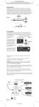
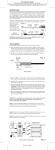
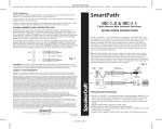
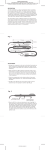
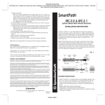
PRINTER’S INSTRUCTIONS:
INSTR,INSTL,IRE-1.0 • LINEAR P/N: 223101X20 • INK: BLACK •
MATERIAL: 20LB. GLOSS WHITE PAPER • SIZE: 4.250” X 17.500” FOLD TO 4.250” X 3.500”
• FOLDING: 5 PARALLEL FAN-FOLDS, FINISH WITH LOGO SHOWING • SCALE: 1-1
DESCRIPTION
The IRE-1.0 represents the highest level in sophistication for attachable
IR Emitters. It features a unique EZ-Docker™ port that permits instant
removal of the emitter when rearranging or servicing components.
An improved adhesive reduces callbacks for reattachment of “fallen
emitters”. The case may also be taken apart so that the tiny internal
emitter can be placed inside a component, when desired. High IR
output from the top curved surface allows emitter to be mounted
on a nearby surface, below, above or on a cabinet door, rather than
directly on the sensor of the unit where conditions permit.
IRE-1.0
Emitter
Top View
3.5mm
mini plug
(+)
NOTE: White striped side is positive ( +)
7/16"
(– )
9/16"
8 FT
Fig. 1
Side View
Emitter
Wire Lead
Clear Adhesive Tape
(See Note 3)
Docking
Port
Emitter slides into
Docking Port
1/4"
ATTACHMENT
First, locate the component’s IR sensor window (see Note 1) and
thoroughly clean it of any fingerprints or other greasy substances.
The EZ-Docker™ port has a clear adhesive layer on its bottom surface.
Peel the protective layer off,
IR Controlled Components
exposing the adhesive.
Orient the port vertical (see
Fig. 2) and press it over the
center of the component’s
sensor window. Press and
hold for several seconds to
ensure maximum contact
of the adhesive.
1) Attach IRE-1.0 Docking Port
to IR sensor window with adhesive pad
Slide the emitter from the
top down, into the EZDocker™ port. You should
feel it “snap” into place. (To
remove the emitter at any
time, simply push upward
until it “pops” out).
Fig. 2
2) Slide IRE-1.0 Emitter
end into docking port
Docking Port
IRE-1.0 attached to
IR sensor window
IR sensor
window
Insert the 3.5mm plug into an Emitter jack on a SpeakerCraft
Terminator or other source of IR (see Fig. 3).
CAUTION: Do not plug into an emitter jack that is set to Blaster
Power (BL ON) or to the HIGH OUT of other connecting blocks.
To do so will smoke the emitters!!
Note 1: If you have difficulty finding the component’s IR sensor, try
using a flashlight. Sometimes the owner’s manual is helpful. You may
need to contact the manufacturer direct.
Note 2: You may also attach the emitter without the EZ-Docker™
port. Use one of the spare adhesives (included) applying it directly to
the bottom surface of the IRE-1.0 shell.
Note 3: If you need to remove the EZ-Docker™ port or emitter previously stuck to a component’s surface, use a fresh adhesive (included)
before reattaching.
Note 4: The emitter shell and EZ-Docker™ port, though dark in
appearance, are transparent to Infrared. This allows IR commands
to pass through them, permitting local hand held remote control as
well as through the IRE-1.0.
TYPICAL INSTALLATION
IRC-3.0
Shelf Top
IR Receiver
Hand Held
Remote
IR Sensor
Window
Satellite Receiver
IRE-1.0
AT-1.0
Amplified Terminator
Unit
Emitter
VCR
IRE-1.0
Emitter
A/V Receiver
IRE-1.0
Emitter
Fig. 3
PS-1.0
Power Supply
120V AC
(unswitched)
223101X20 • IMAGE 1
PRINTER’S INSTRUCTIONS:
INSTR,INSTL,IRE-1.0 • LINEAR P/N: 223101X20 • INK: BLACK •
MATERIAL: 20LB. GLOSS WHITE PAPER • SIZE: 4.250” X 17.500” FOLD TO 4.250” X 3.500”
• FOLDING: 5 PARALLEL FAN-FOLDS, FINISH WITH LOGO SHOWING • SCALE: 1-1
ELT03100
SpeakerCraft
LIT03100 (rev2)
223101X20
INSTALLATION INSTRUCTIONS
IR Emitter
IRE-1.0
®
SmartPath™
Fig. 4
Internal
IR Emitter
High
output
side
Low
output side
toward IR
sensor
Emitter
Shell
Connecting
lead
Other Emitter Placements
Since the IRE-1.0 has high output from it’s curved top (See Fig. 4),
you may attach it to other surfaces nearby, if the installation permits.
(See Fig. 5)
Use the higher power setting (NOT Blaster Power) on the connecting block or terminator, if so provided.
Some installers like the option of placing the emitter completely inside
a component, as near as possible to the IR sensor, for a clean external
appearance. In some cases, the whole emitter can be so placed.
In others, it may be necessary to remove the internal emitter from its
shell so that it will fit in tiny chassis places. In this case, use the thin
edge of a knife to carefully pry the lower cover from the shell of the
emitter. Gently ease the tiny emitter and lead from it’s nest within the
shell. Use heat shrink tubing, or other insulating means, to prevent
shorting of the exposed leads.
IR Controlled Components
IR Sensor
Window
Cabinet Door
Fig. 5b IRE-1.0 attached to inside of
Fig. 5a IRE-1.0 attached directly
cabinet door directly opposite
IR sensor window
to IR sensor window
Fig. 5
Fig. 5c & d IRE-1.0 attached to shelf directly
below or above IR sensor window
LIMITED 5-YEAR WARRANTY
SpeakerCraft Inc. warrants to the original retail purchaser only that this
SpeakerCraft product will be free from defects in materials and workmanship, for a period of 5-years, provided it was purchased from a SpeakerCraft
Authorized Dealer.
Defective products must be shipped, together with proof of purchase,
prepaid insured to the SpeakerCraft Authorized Dealer from whom they
were purchased, or to the SpeakerCraft factory at the address listed on this
installation instruction manual. Freight collect shipments will be refused. It
is preferable to ship this product in the original shipping container to lessen
the chance of transit damage. In any case, the risk or loss or damage in
transit is to be borne by the purchaser. If upon examination at the Factory
or SpeakerCraft Authorized Dealer it is determined that the unit was defective in materials or workmanship at any time during this warranty period,
SpeakerCraft or the SpeakerCraft Authorized Dealer will, at its option, repair
or replace this product at no additional charge, except as set forth below.
If this model is no longer available and can not be repaired effectively,
SpeakerCraft, at its sole option may replace the unit with a current model of
equal or greater value. In some cases where a new model is substituted, a
modification to the mounting surface may be required. If mounting surface
modification is required, SpeakerCraft assumes no responsibility or liability
for such modification. All replaced parts and product become the property
of SpeakerCraft Inc. Products replaced or repaired under this warranty
will be returned to the original retail purchaser, within a reasonable time,
freight prepaid.
This warranty does not include service or parts to repair damage caused
by accident, disaster, misuse, abuse, negligence, inadequate packing or
shipping procedures, commercial use, voltage inputs in excess of the rated
maximum of the unit, or service, repair or modification of the product which
has not been authorized or approved by SpeakerCraft. This warranty also
excludes normal cosmetic deterioration caused by environmental conditions.
This warranty will be void if the Serial number on the product has been
removed, tampered with or defaced.
This warranty is in lieu of all other expressed warranties. If the product is
defective in materials or workmanship as warranted above, the purchaser’s
sole remedy shall be repair or replacement as provided above. In no event
will SpeakerCraft be liable for any incidental or consequential damages
arising out of the use or inability to use the product, even if SpeakerCraft
Inc. or a SpeakerCraft Inc. Authorized Dealer has been advised of the possibility of such damages, or for any claim by any other party. Some states
do not allow the exclusion or limitation of consequential damages, so the
above limitation and exclusion may not apply. All implied warranties on the
product are limited to the duration of this expressed warranty. Some states
do not allow limitation on the length of an implied Warranty. If the original
retail purchaser resides in such a state, this limitation does not apply.
SpeakerCraft
Phone 1-800-448-0976
®
940 Columbia Avenue, Riverside, CA 92507
•
www.speakercraft.com
2
223101X20 • IMAGE 2
•
Fax 951-787-8747