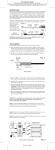
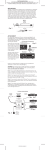
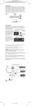
1
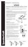
PRINTER’S INSTRUCTIONS:
INSTR,INSTL,IRC-2 • LINEAR P/N: 223166B • INK: BLACK • MATERIAL: 70 LB. GLOSS WHITE COATED PAPER • SIZE: 11.000” X 8.500” FOLD TO 5.500” X 8.500” • FOLDING: 1 FOLD VERTICAL, FINISH WITH LOGO SHOWING • SCALE: 1-1
controlled components.
Note: Use 24 gauge unshielded solid or stranded copper wire up to 1200' (Cat. 5e
ok), 22 gauge up to 2000', 20 gauge up to 3000' and 18 gauge up to 5300'. Total
lengths include all wire runs from each room added together, not just the longest
single run. If using shielded wire, these lengths would be reduced by approximately
30%. Also, to achieve operation with long lengths, the lower DIP switch on the
AT-1.0 must be set to the NET ON position.
2. Connect IR receivers in each room to the 4-conductor home runs as shown, using the
4-conductor terminal strip supplied.
3. Connect the home run wires to the correct terminals on the AT-1.0 EZ-Connect Terminals.
Note: You may use the SpeakerCraft CB Connecting Block (not illustrated, stock
# ASM20200) to help connect the many paralleled home run wires to the AT-1.0
EZ-Connect Terminals.
4. Install and plug the various emitters into the AT-1.0.
5. Set the DIP switches to EM ON (or BL ON if using Blasters behind closet doors) and
NET ON.
6. Plug the local IRC-2.0 IR Receiver into the IR RCVR jack.
7. Plug in the PS-1.0 12V DC Power Supply.
8. A remote control, fired at the IR receivers, should now control the components.
Note: Refer to the SpeakerCraft AT-1.0 Instructions for Power Supply considerations.
STATUS Brightness
Fig. 3 also shows how an external resistor can be added to reduce the brightness of the
Status LED’s on SpeakerCraft IR Receivers to any desired level.
SmartPath
™
IRC-2.0 & IRC-2.1
Surface Mount Mini Infrared Receivers
INSTALLATION INSTRUCTIONS
The IRC-2.0 and IRC-2.1 are very small IR Receivers designed to be mounted on
flat surfaces in furniture recesses, under shelves, etc., using the double-sided tape
supplied. Among their unique features is an exclusive Ambient Noise Suppression
(ANS) system. It acts to push down IRI, CFL, EMI, or ESI noise sources so that stronger signals from IR remotes have adequate margin for command of the
controlled component.
Note: The ANS will take a few seconds to adjust to a given noise source. During
this time, the blue Activity LED will glow brightly and then fade out. If the interference disappears momentarily, then returns, the fade down process will repeat.
Certain noise sources, however, (such as Plasma Screens) may result in low-level flickering even after the fade down. This is normal. Such signals have been acted upon
by the ANS, allowing most equipment to be controlled.
In this example, a PS-1.0 12V DC Power Supply is used as the voltage source to indicate
ON/OFF status of an A/V Receiver.
Fig. 1
Choose a resistor value that achieves the brightness you desire (about 2.2k to 12k, 1/8 W).
Connect it in series with the STATUS lead on each IR receiver desired, as shown.
LIMITED 5-YEAR WARRANTY
SpeakerCraft Inc. warrants to the original retail purchaser only that this SpeakerCraft product will be free from defects in materials and
workmanship, for a period of 5-years, provided it was purchased from a SpeakerCraft Authorized Dealer.
Defective products must be shipped, together with proof of purchase, prepaid insured to the SpeakerCraft Authorized Dealer from
whom they were purchased, or to the SpeakerCraft factory at the address listed on this installation instruction manual. Freight collect
shipments will be refused. It is preferable to ship this product in the original shipping
container to lessen the chance of transit damage. In any case, the risk or loss or damage in transit is to be borne by the purchaser.
If upon examination at the Factory or SpeakerCraft Authorized Dealer it is determined that the unit was defective in materials or
workmanship at any time during this warranty period, SpeakerCraft or the SpeakerCraft Authorized Dealer will, at its option, repair or
replace this product at no additional charge, except as set forth below.
If this model is no longer available and can not be repaired effectively, SpeakerCraft, at its sole option may replace the unit with a current model of equal or greater value. In some cases where a new model is substituted, a modification to the mounting surface may
be required. If mounting surface modification is required, SpeakerCraft assumes no responsibility or liability for such modification.
All replaced parts and product become the property of SpeakerCraft Inc. Products replaced or repaired under this warranty will be
returned to the original retail purchaser, within a reasonable time, freight prepaid.
This warranty does not include service or parts to repair damage caused by accident, disaster, misuse, abuse, negligence, inadequate
packing or shipping procedures, commercial use, voltage inputs in excess of the rated maximum of the unit, or service, repair or
modification of the product which has not been authorized or approved by SpeakerCraft. This warranty also excludes normal cosmetic
deterioration caused by environmental conditions. This warranty will be void if the Serial number on the product has been removed,
tampered with or defaced.
This warranty is in lieu of all other expressed warranties. If the product is defective in materials or workmanship as warranted above,
the purchaser’s sole remedy shall be repair or replacement as provided above. In no event will SpeakerCraft be liable for any incidental or consequential damages arising out of the use or inability to use the product, even if SpeakerCraft Inc. or a SpeakerCraft Inc.
Authorized Dealer has been advised of the possibility of such damages, or for any claim by any other party. Some states do not allow
the exclusion or limitation of consequential damages, so the above limitation and exclusion may not apply. All implied warranties on
the product are limited to the duration of this expressed warranty. Some states do not allow limitation on the length of an implied
Warranty. If the original retail purchaser resides in such a state, this limitation does not apply.
940 Columbia Avenue, Riverside, CA 92507 • 800-448-0976 • Fax 888-599-9059
www.speakercraft.com
LIT01200 (rev2)
223166B
223166B • IMAGE 1
IR Lens
Status LED
(green)
IR OUT
GND
+12V DC
STATUS
Activity LED
(blue)
IRC-2.0
IR Pickup Diode
Striped Side
9/16"
8' Lead
4-Conductor
3.5mm Plug
2-9/16"
+12V
4-Conductor
Terminal Strip
GND
IRC-2.1
STATUS
Striped Side
IR OUT
(Included with
IRC-2.1 Only)
FEATURES/SPECIFICATIONS
• The IRC-2.0 and IRC-2.1 are identical except for lead termination. (See Fig. 1) The
IRC-2.0 has a unique 3.5mm quad plug to accommodate STATUS as well as IR,
Power and Gnd connections. The IRC-2.1 comes with stripped ends plus a 4conductor terminal strip allowing interface connections to in-wall room-to-room
wiring.
• Exclusive Ambient Noise Suppressor (ANS) system.
• STATUS Indicator: Green LED for System On/Off indication.
• ACTIVITY Indicator: Blue LED indicates IR signal activity in a completed circuit with
a Terminator or an Emitter.
PRINTER’S INSTRUCTIONS:
INSTR,INSTL,IRC-2 • LINEAR P/N: 223166B • INK: BLACK • MATERIAL: 70 LB. GLOSS WHITE COATED PAPER • SIZE: 11.000” X 8.500” FOLD TO 5.500” X 8.500” • FOLDING: 1 FOLD VERTICAL, FINISH WITH LOGO SHOWING • SCALE: 1-1
• Requires Power Supply, Terminator Block and Emitters for IR Repeater operation.
• Mounting: Attaches to any flat surface using the included double-sided tape. The tape may
be applied to the back, top, or bottom surfaces of the IRC-2.0 / IRC-2.1 to accommodate
the installation.
• Power: 12V DC @ 6 mA. Supplied from connected Terminator.
• IR Lens rejects visible light interference.
• Crosshatch Shield (internal) inhibits EMI/ESI Interference.
• Carrier Frequency Acceptance Range: 28 to 90 kHz.
• Control Range: Up to 35 feet, depending on remote strength and ambient noise conditions.
• Control Angle: ±50˚ off axis.
• Room-to-Room Wire Recommendations: Use 4-conductor (min.) 24 gauge unshielded
solid or stranded copper wire up to 1200' (Cat. 5e ok), 22 gauge up to 2000', 20 gauge
up to 3000' and 18 gauge up to 5300'.
• Maximum recommended cable length: 5300' with 18 gauge.
• Dimensions: 29⁄16" (65mm) L x 9⁄16" (14mm) W x 1⁄2" (13mm) D.
A Multi-Room System
Fig. 3 is an example of the IRC-2.1 wired IR Receiver in a multi-room system with other
SpeakerCraft IR receivers in various rooms, plus a local IRC-2.0. These control the various
components in the main room or equipment area.
1. Pull 4-conductor wire from each room (home runs) to the AT-1.0 Terminator near the
Fig. 3
ROOM 2
ROOM 1
IRC-2.1
IRC-4.0
Surface Mount IR Receiver
J-Box IR Receiver
IRC-4.0
Striped
Side
J-BOX
IR RECEIVER
A Basic System
Fig. 2 shows a basic plug-and-play installation, such as controlling components that are
behind closed cabinet doors or in a closet.
IRC-1.1
Flush Mount IR Receiver
IR OUT
ST IN
The following are a few typical applications of the IRC-2.0 and IRC-2.1 for IR repeater systems.
GND
+12V
SYSTEM CONNECTIONS
ROOM 3
SpeakerCraft
IR OUT
IR OUT
®
(red)
STATUS
GND
STATUS
+12V
(white)
+12V
GND
(yellow)
(black)
Fig. 2
CONTROLLED COMPONENTS IN CABINET, ETC.
A/V Receiver
Rear View
8' Lead
Add Resistor at each IR receiver
to reduce STATUS brightness,
if desired. See Text.
IRC-2.0
Surface Mount
IR Receiver
EZ-Connect Terminals
IRE-3.0 Visible Emitter
+12V
GND
ST OUT
IR IN
EMITTERS
AT-1.0
AMPLIFIED
TERMINATOR
SpeakerCraft
EM ON
EM ON
NET OFF
PS-1.0
IRE-1.0 Emitter
"STATUS"
Supply
Satellite
®
BL ON
BL ON
NET ON
EMITTERS /
BLASTERS
Remote Control
GND
+12V
ST OUT
IR IN
DVD
12V DC
REGULATED
To 120V AC
(unswitched)
AT-1.0
STATUS IN
5~24V DC
PS-1.0
EMITTERS /
BLASTERS
12V DC
REGULATED
BL ON
BL ON
NET ON
IR
RCVR
STATUS IN
5~24V DC
IRE-3.0 Visible Emitter
®
EM ON
EM ON
NET OFF
Surface Mount
IR Receiver
EMITTERS
IR
RCVR
AT-1.0
AMPLIFIED
TERMINATOR
A/V Receiver
IRC-2.0
Satellite
SpeakerCraft
Power
Supply
To Switched
AC Outlet on
A/V Receiver
IRE-3.0 Visible Emitter
DVD
IRE-3.0
Visible Emitter
AT-1.0
Amplified Terminator
PS-1.0
1. Mount the IRC-2.0 in a recessed cabinet area or under a shelf, using the two-sided
adhesive tape supplied.
2. Plug the IR Receiver and Emitters into the SpeakerCraft AT-1.0 Amplified Terminator, as
shown.
3. Set the DIP switches on the AT-1.0 to EM ON and NET ON or OFF.
4. Plug in the Power Supply.
5. The remote control, fired at the IRC-2.0, should now control the components.
Power
Supply
Amplified Terminator
To 120V AC
(unswitched)
223166B • IMAGE 1
Visible Emitter
To Additional
Controlled Unit
CONTROLLED COMPONENTS AREA, MAIN ROOM, ETC.
3
2
IRE-4.0 Dual