1
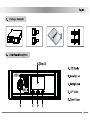
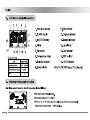
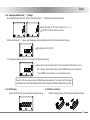
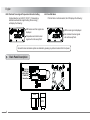
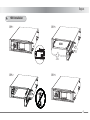
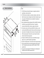
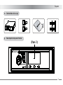
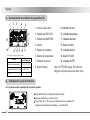
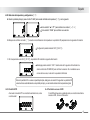
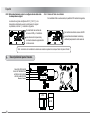
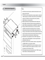
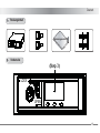
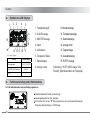
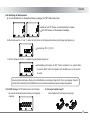
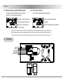
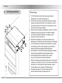
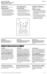
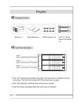
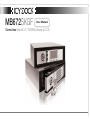
MB672SKGF
User Manual
Screw-less Internal 3.5 “ SATA Enclosure w/ LCD
English
<4-2> Temperature Detection and ʚ0ʛ Settings:
A. From Main Display, press “SET” button to enter Temperature ʚ0ʛ!SettinMod and display the following:
Шʳ
• Press ”▲” button or “ ▼” button to switch the ʚʈʛʈʚ/
• Press “SET” button to confirm your choice.
Ч
B. After confirming the ʚ0ʛ mode, enter Temperature detection Setting mode.The LCD screen flashes the following:
• Default setting: 50.0ʚ(122.0ʛ).
C. If setting temperature at 55.0ʚ(131.0ʛ), the LCD will display the following:
• Press “▲” to set the temperture to 55.0ʚ. Press and hold the “SET” button for more
than 3 seconds, and the alarm buzzer will sound “BEEP” twice as choice confirmed.
If sound “BEEP” is less than twice, it is not a confirmed choice.
Remark: If LCD screen does not return to Main Display, stop operation for 15 seconds, the LCD will then
automatically return to the Main Display and the original tempera ture detection setting will be cancelled.
<4-3> HUTR Display
<4-4> HDD Access Display
To enter the HUTR mode, the Hour signal is displayed as below:
day
If HDD is reading or writing, HDD access signal displays the below:
hr
3
English
<4-5> Overheat from original Temperature Detection Setting
<4-6> Fan Fail Alarm
If the fan fails or is disconnected, the LCD displays the followingǺ
Original detection set at 50.0ʚ(122.0ʛ), if temperature
detected overheats the original setting. Screen using ʚ
will display the followingǺ
• HDD access and Fan signals are
displayed.
• Temperature and alarm buzzer
signals will continuously flash.
• HDD access signal is displayed.
• Fan and alarm buzzer signals
will continuously flash.
Remark: Buzzer and alarm symbol are disabled by pressing any buttons located at the front panel.
5.
Back Panel Description
FAN FAIL
TEMP FAIL
HDD ACCESS
POWER LED
Master/Slave
4 PIN
SATA
4
English
6.
HDD Installation
STEP 1
STEP 3
HDD
B
PULL
A
STEP 2
STEP 4
5
English
7.
Device Installation
Note:
1. ICY DOCK reserves the right to change or to upgrade any technical
specifications without prior notice.
2. ICY DOCK will not be liable for any software, hardware, and/or stored
data that may be become damaged or dysfunctional through the usage
of our product. ICY DOCK will only be responsible for repairing and
servicing its own product.
3. Due to specification differences between SATA I and SATA II hard drives,
the LED will only work with SATA II hard drives. To enable the
enclosure’s LED with SATA I hard drives, please refer to Note 4.
4. To allow the enclosure’s LED to work with SATA I hard drives, you will
need an optional HDD Access cable. Please connect the Access signal
pins provided on the backplane of the enclosure to the respective Host
Port’s Access signal pins. Please refer to your host port’s instruction
manual to locate its Access signal pins.
5. To determine if SATA II hard drives have built in HDD Access signal,
please refer to your HDD manufacture specifications.
6. To perform hot-swap function, the host side must also support hot-swap.
7. In the event that the LCD is not functioning properly, please reset the
LCD. If the problem persists, please contact the nearest ICY DOCK
support center.
8. For any further inquiries about ICY DOCK product or related product
information, please visit http://www.icydock.com.
6
Español
1.
Contenidos de la caja
2.
Descripción del panel frontal
(Paso 3)
Bloqueo
Abierto
7
Español
3. Descripción de los símbolos de la pantalla LCD
1
2
15
14
4
3
5
day
hr
13 12 11 10
1. Acceso a disco duro
9. Indicador de hora
6
2. Pantalla de ESCLAVO
10. Indicador de grados
7
8
3. Pantalla de MAESTRO
11. Indicador decimal
4. Alarma
12. Selector Arriba
5. Estado de ventilador
13. Indicador de día
6. Estado de temperatura
14. Selector FIJAR
9
Dpogjhvsbdjôo!qsfefufsnjobeb
Elemento
Detección de temperatura
Pantalla MAESTRO/ESCLAVO
HUTR
Configuración
predeterminada
15. Indicador HUTR
7. Indicador numérico
50.0к (122.0л)
8. Selector Abajo
ESCLAVO
Nota: HUTR (HDD Usage Time Record,
Registro de tiempo de uso de disco duro)
0
4. Configuración y uso de funciones
<4-1> Si está encendida, la pantalla LCD mostrará lo siguiente:
• Modo HDD: ESCLAVO (configuración predeterminada)
• Temperatura ambiente si es inferior a 30.6к
• Pulse el botón ”▲” o ” ▼” para ver los distintos modos en la pantalla LCD:
Configuración de detección de temperatura → Pantalla HUTR.
8
Español
<4-2> Detección de temperatura y configuración ʚ0ʛ:
A. Desde la pantalla principal, pulse el botón ”FIJAR” para acceder al Modo de temperatura ʚ0ʛ y ver lo siguiente:
Шʳ
• Pulse el botón ”▲” o ”▼ ” para cambiar a los modos ʚʈʛʈʚ.
• Pulse el botón “FIJAR” para confirmar su selección.
Ч
B. Después de confirmar el modo ʚ0ʛ, acceda al modo Detección de temperatura. La pantalla LCD parpadeará con la siguiente información:
• Configuración predeterminada: 50.0ʚ(122.0ʛ).
C. Si la temperatura es de 55.0ʚ(131.0ʛ), la pantalla LCD mostrará la siguiente información:
• Mantenga pulsado el botón ” SET ” durante más de 3 segundos. El zumbador de
alarma emitirá dos “SONIDOS” para confirmar la elección. Si el zumbador suena
menos de dos veces, la elección no quedará confirmada.
Nota: si la pantalla LCD no vuelve a la pantalla principal, detenga el uso durante 15 segundos. La pantalla LCD
volverá entonces automáticamente a la pantalla principal, y se cancelará la detección de temperatura original.
<4-3> Pantalla HUTR
<4-4> Pantalla de acceso al HDD
Al acceder al modo HUTR se mostrará la señal de Hora, como
a continuación:
day
Si el HDD está leyendo o grabando datos, se mostrará la señal de
acceso a HDD, como a continuación:
hr
9
Español
<4-5> Sobrecalentamiento sobre la configuración de detección
de temperatura original
<4-6> Alarma de fallo de ventilador
Si el ventilador falla o se desconecta, la pantalla LCD mostrará lo siguiente;
La detección original está fijada a 50.0ʚ(122.0ʛ), si la
temperatura detectada excede la configuración original.
La pantalla, al utilizar ʚ, mostrará lo siguiente:
• Se mostrarán las señales de
acceso al HDD y al Ventilador.
• Se mostrará la señal de acceso al HDD.
• Las señales dezumbador de alarma y
ventilador parpadearán continuamente.
• Las señales de temperatura y
zumbador dealarma parpadearán
continuamente.
Nota: el símbolo del zumbador de alarma se desactiva pulsando cualquier botón del panel frontal.
5.
Descripción del panel trasera
FALLO DE VENTILADOR
FALLO DE TEMPERATURA
ACCESO A DISCO DURO
LED DE ALIMENTACIÓN
Maestro / Esclavo
4 PIN
SATA
10
Español
6.
Instalación de HDD
STEP 1
STEP 3
HDD
B
TIRAR
A
STEP 2
STEP 4
11
Español
7.
Instalación del dispositivo
Nota:
1. ICY DOCK se reserva el derecho a realizar cambios sobre los niveles
técnicos sin aviso previo.
2. ICY DOCK no se hace responsalbe de cualquier programa, componente
o dato almacenado o conectado nuestro producto que resulte dañado o
averiado. ICY DOCK sólo se hará responsible de la reparación y
mantenimiento de su propio producto.
3. Debido a las diferencias en las especificaciones entre los discos duros
SATA I y SATA II, el LED sólo funcionará con discos duros SATA II. Para
activar el LED de la carcasa utilizando una unidad SATA I, consulte la Nota 4.
4. Para que el LED de la carcasa funcione con un disco duro SATA I
necesitará un cable de acceso opcional a disco duro. Conecte los
terminales de señal de acceso suministrados al panel posterior de la
carcasa y a los terminales de señal de acceso respectivos del puerto del
equipo. Consulte el manual de instrucciones del puerto del equipo para
conocer la posición de los terminales de la señal de acceso.
5. Para determinar si las unidades de disco duro SATA II disponen de
señales de acceso a HDD integradas, consulte las especificaciones
de fabricación del disco duro.
6. Para llevar a cabo la función de cambio en caliente, el equipo debe ser
compatible también con la conexión en caliente.
7. En caso de que la pantalla LCD no funcione correctamente, reinicie la
pantalla. Si el problema continúa, póngase en contacto con el centro
de asistencia de ICY DOCK más cercano.
8. Si tiene alguna duda acerca de algún producto de ICY DOCK o desea
más información, visite http://www.icydock.com.
12
Deutsch
1.
Packungsinhalt
Bedienungsanleitung
2.
Vorderseite
(Step 3)
LOCK
OPEN
13
Deutsch
Symbole des LCD Displays
3.
1
2
4
3
15
5
day
14
hr
13 12 11 10
1. Festplattenzugriff
9. Stundenanzeige
6
2. SLAVE Anzeige
10. Temperaturanzeige
7
8
3. MASTER Anzeige
11. Dezimalanzeige
4. Alarm
12. Anzeige hoch
5. Lüfterstatus
13. Tagesanzeige
6. Temperatur Status
14. Auswahlanzeige
9
Wpsfjotufmmvohfo
Position
Warntemperatur
MASTER/SLAVE Betriebsart
HUTR
4.
Voreinstellungen
50.0к (122.0л)
SLAVE
15. HUTR* Anzeige
7. Zahlendisplay
8. Anzeige runter
Anmerkung: *HUTR (HDD Usage Time
Record), (Betriebsstunden der Festplatte)
0
Funktionseinstellung und in Betriebnahme
<4-1> Bei in Betriebnahme zeigt das Display folgendes an:
• Festplatten Betriebsart: SLAVE (Voreinstellung)
• Umgebungstemperatur bei 30.6к (Beispiel)
• Durch drücken der ”▲” oder ” ▼” Taste, gelangt man zu den verschiedenen Einstellungen:
Temperature Detection Setting→ HUTR Display.
14
Deutsch
<4-2> Einstellung der Warntemperatur:
A. Um vom Startbildschirm zur Temperatureinstellung zu gelangen, die “SET” Taste drücken. Dann:
Шʳ
• Taste ”▲” oder ”▼” drücken, um durch die Menüs zu schalten.
• Taste “SET” drücken, um die Auswahl zu bestätigen.
Ч
B. Nach der Auswahl von ʚ oder ʛ , wählen Sie die Funktion zur Warntemperatureinstellung. Das Display zeigt folgendes an:
• Voreinstellung: 50.0 ʚ(122.0ʛ).
C. Wird die Temperatur auf 55.0 ʚ eingestellt zeigt das Display folgendes an:
• Zur Bestätigung der Eingabe, die ”SET” Taste für mindestens 3 sec. gedrückt halten,
bis zwei Mal „BEEP“ ertönt. Die Eingabe ist nicht bestätigt, wenn nur ein oder kein
Ton ertönt.
Anmerkung: Sollte die Anzeige im Display nicht zum Startbildschirm zurückkehren, tätigen Sie für 15 sec. keine Eingaben. Daraufhin
kehrt das Gerät automatisch auf den Startbildschirm zurück und die Grundeinstellungen werden entsprechend geändert.
<4-3> HUTR* Anzeige (*HUTR: Betriebsstunden der Festplatte)
Bei Auswahl der Betriebsstundeneinstellung wird folgendes
angezeigt:
day
<4-4> Anzeige Festplattenzugriff
Bei Festplattenzugriff wird folgendes angezeigt:
hr
15
Deutsch
<4-5> Überschreitung der eingestellten Warntemperatur
<4-6> Warnung bei Lüfterfehler
Wenn der Lüfter ausfällt, wird folgendes angezeigt:
Bei Überschreitung der eingestellten Warntemperatur
(Beispiel 50° C) wird folgendes angezeigt:
• Symbol für Festplattenzugriff und
• Symbol für Festplattenzugriff wird
Lüftersignal werden dargestellt.
dargestellt.
• Temperatur und Alarmglocke
• Lüfter und Alarmglocke leuchten ständig.
leuchten ständig.
Anmerkung: Alarmsignal und –anzeige können durch drücken einer Taste in der Front deaktiviert werden.
5.
Rückseite
FAN FAIL
TEMP FAIL
HDD ACCESS
POWER LED
MASTER/SLAVE
4 PIN
SATA
16
Deutsch
6.
HDD Installation
STEP 1
STEP 3
HDD
B
PULL
A
-
STEP 2
STEP 4
17
Deutsch
7.
Vorrichtung Installation
Bemerkungen:
1. ICY DOCK behält sich das Recht auf Änderungen technischer
Spezifikationen ohne weitere Ankündigungen vor.
2. ICY DOCK übernimmt keine Verantwortung für Schäden an Software,
Hardware oder gespeicherten Daten, die in Verbindung mit unserem
Produkt genutzt werden. ICY DOCK ist nur für die Reparatur und den
Service der eigenen Produkte zuständig.
3. Aufgrund der unterschiedlichen Spezifikationen von SATA I und SATA II
Festplatten, arbeitet die Anzeige LED nur mit SATA II Festplatten.
Um die Nutzung mit SATA I Festplatten zu ermöglichen, gehen
Sie wie unter Punkt 4 beschrieben vor.
4. Damit SATA I Festplatten mit der Anzeige LED arbeiten können,
benötigen Sie ein Zusatzkabel. Dieses wird benötigt, um die LED Signal
Pins des Produktes mit den Signal Pins des Mainboards zu verbinden.
Zur Lokalisierung der Pins auf dem Mainboard, lesen Sie bitte die
Bedienung sanleitung des jeweiligen Mainboardherstellers.
5. Um festzustellen, ob Ihre SATA II Festplatte Zugriffssignale unterstützt,
überprüfen Sie die Spezifikationen des Festplattenherstellers.
6. Um die Hot Swap Funktion des Gerätes nutzen zu können,
muss auch der Computer diese Funktion unterstützen.
7. Sollte die LCD Anzeige nicht einwandfrei funktionieren, führen Sie bitte
ein Reset, wie unter Punkt ???(muss ich noch am Gerät nachvollziehen)
beschrieben aus. Sollte das Problem weiterhin bestehen, nehmen
Sie bitte Kontakt zu Ihrem nächsten ICY DOCK Händler auf.
8. Für weitere Informationen, ICY DOCK Produkte betreffend,
besuchen Sie bitte die Seite: http://www.icydock.com
18
650104 2007 VER.1.0