1
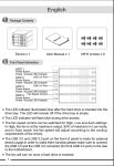
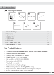
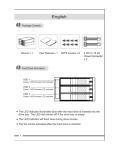
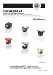
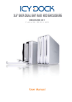
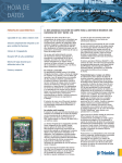
MB673SPF 3 HDD Slots in 2 Device Bay
Screw-Less SATA Backplane Module
User Manual
English
1.
Package Contents
Front Panel’s LED Signal Explanation
2.
HDD1 Power/Failure Indicator
Access Indicator
OVER HEAT
HDD2 Power/Failure Indicator
Access Indicator
Product
RESET
HDD3 Power/Failure Indicator
Access Indicator
FAN FAIL
Red
Instruction Manual!!!!
Button Head M3 x 12 pcs
Orange
Green
<2.1> The front panel LED HDD signal can display 3 different colors for quick status checks:
A. When the HDD is fully functional and is receiving power, the LED will show a green light.
B. When the HDD is reading or writing data, the LED will show a flashing orange light.
C. When the HDD is damaged or non-functional, the LED will show red light. (This signal should be
provided by the HOST (motherboard or controller card). Please refer to 2.2)
<2.2> HDD fail signal:
A. This product can not provide this signal, unless the HOST (Motherboard or Controller card)
supports this function.
B. If the HOST can provide the HDD fail signal, the cable needs to be connected to the HOST and
to the backplane’s HDD Fail 1, 2, 3. (See Page 2).
C. When the HDD is damaged, the HDD fail signal will show red light color.
1
English
<2.3> Damaged cooling fan and product overheat warning:
NOTE: After the cooling fan is removed, the FAN FAIL system and alarm will not transmit any signals.
A. When the cooling fan stops running or fails, the fan fail light will display a red light and then the alarm will start to sound. You must
press the RESET button to stop the alarm, but the red light will still be on until the fan is removed or replaced.
B. Temperature Alarm Feature:
The temperature trigger can be set at the following temperatures: 45ʚ, 55ʚ, 65ʚ. (See Section 3.)
C. When the product temperature exceeds the set temperature, the OVER HEAT LED will display red and the alarm will sound.
If this issue occurs please press the RESET button to stop the alarm, but the OVER HEAT LED will remain on until the
temperature is below the set temperature.
3.
Back Plane Description (Labeled on the top side of the Product)
HDD1
45
55
65
HDD1 FAIL IN
HDD2 FAIL IN
HDD3 FAIL IN
HDD FAIL IN
HDD2
TEMP SET
HDD3
S-OUT
POWER PORT
2
SATA CONNECTOR
POWER1
POWER2
POWER3
ACCESS1
ACCESS2
ACCESS3
TEMP FAIL
FAN FAIL
RESET
English
4.
Operating Instructions
<A> After pushing down the eject button, the door handle will eject. Then pull the door open using the door handle
to access the HDD bay.
PUSH
PULL
<B> After the HDD is completely inserted into the drive bay, push the door closed until the drive is secure.
HDD
3
English
<C> The cooling fan is removable when it is not needed. After the cooling fan is removed the FAN FAIL system and alarm will not transmit any
signals. ( When the cooling fan is removed the Fan Fail Alarm will be disabled.)
PUSH
ɀ Backplane instructions: Please connect 2 x 4-pin molex from the main power source to fully enable the device.
Noteǽ
1. HDD failure will indicate red only when the signals are transmitted by HOST (Please refer to the HDD-fail Signal)
2. The testing condition were at the surrounding temperature at 25°C
3. ICY DOCK reserves the right to change or to upgrade any technical specifications without prior notice.
4. ICY DOCK will not be liable for any software, hardware, and/or stored data that may be become damaged or dysfunctional through the usage
of our product. ICY DOCK will only be responsible for repairing and servicing its own product.
5. Due to specification differences between SATA I and SATA II hard drives, the LED will only work with SATA II hard drives. To enable the
enclosure’s LED with SATA I hard drives, please refer to Note 4.
6. To allow the enclosure’s LED to work with SATA I hard drives, you will need an optional HDD Access cable. Please connect the Access signal
pins 1, 2, 3 provided on the backplane of the enclosure to the respective Host Port’s Access signal pins. Please refer to your host port’s
instruction manual to locate its Access signal pins.
7. To determine if SATA II hard drives have built in HDD Access signal, please refer to your HDD manufacture specifications.
8. To perform hot-swap function, the host side must also support hot-swap.
9. For any further inquiries about ICY DOCK product or related product information, please visit: www.icydock.com
4
Español
1.
Contenido de la caja
2.
Instrucciones de las señales LED del panel frontal
HDD1 Power/Failure Indicator
Access Indicator
OVER HEAT
HDD2 Power/Failure Indicator
Access Indicator
producto
RESET
HDD3 Power/Failure Indicator
Access Indicator
FAN FAIL
Rojo
Manual de instrucciones!!
tornillos M3 del Disco Duro x 12
Naranja
Verde
<2.1> Señal de fallo de HDD:
A. Este producto no ofrece esta señal a menos que el dispositivo anfitrión (placa base o tarjeta controladora)
sea compatible con la misma.
B. Si el anfitrión ofrece señal de fallo de HDD, deberá conectar el cable al anfitrión y a los terminales
HDD Fail 1, 2, 3.
C. Si el HDD está dañado, se activará una luz de color rojo.
<2.2> El ventilador de refrigeración está dañado y el producto activa una advertencia de
sobrecalentamiento:
Función del ventilador: el ventilador se puede retirar si no se necesita. Después de retirar el
ventilador, el sistema FAN FAIL y la alarma no emitirán ninguna señal.
5
Español
A. Si el ventilador se detiene o falla, la luz de fallo de ventilador se iluminará en color rojo y la alarma
comenzará a sonar. Para detener la alarma, pulse el botón de reset. La luz roja permanecerá
encendida hasta retirar o reemplazar el ventilador.
B. Si se retira el ventilador, la alarma se desactivará la alarma de fallo de ventilador.
Temperatura operativa: las temperaturas deben estar dentro del rango 45ʚǵ55ʚǵ65ʚ
C. Si la temperatura del producto excede la temperatura establecida, se iluminará la luz en rojo y la alarma comenzará a sonar.
Si se produce esta situación, pulse el botón RESET para detener la alarma sonora. La luz OVER HEAT permanecerá encendida
(en color rojo) hasta que la temperatura descienda por debajo de la temperatura establecida.
3.
Descripción del panel posterior (pantalla etiquetada en la parte superior del producto)
HDD1
45
55
65
FALLO HDD1 EN
FALLO HDD2 EN
FALLO HDD3 EN
FALLO HDD EN
HDD2
FIJAR TEMP
HDD3
S-OUT
PUERTO DE
ALIMENTACIÓN
6
CONECTOR SATA
ALIMENTACIÓN1
ALIMENTACIÓN2
ALIMENTACIÓN3
ACCESO1
ACCESO2
ACCESO3
FALLO DE TEMP
FALLO DE VENTILADOR
REINICIAR
Español
4.
Instrucciones de uso
<A>
EMPUJAR
TIRAR
<B>
HDD
7
Español
<C> El ventilador puede retirarse si no se necesita. Después de retirar el ventilador, ni el sistema FAN FAIL ni la alarma transmitirán ninguna
señal. ( Una vez retirado el ventilador se desactivará la alarma de fallo de ventilador.)
EMPUJAR
ɀ!Instrucciones del panel posterior: conecte 2 cables de suministro de 4 conductores como principal fuente de alimentación para poner en
marcha el dispositivo.
Notaǽ
1. La señal de fallo de HDD se iluminará en color rojo si las señales son transmitidas por el equipo anfitrión (consulte la sección referente a la señal de fallo de HDD)
2. Las pruebas se han realizado a una temperatura ambiente de 25ºC.
3. ICY DOCK se reserva el derecho a realizar cambios sobre cualquier característica técnica sin aviso previo.
4. ICY DOCK no se hará responsable de ningún software, hardware o dato almacenado en nuestro producto, y que resulte dañado o inhabilitado.
ICY DOCK sólo se hará responsable de la reparación y mantenimiento de su propio producto.
5. Dadas las diferentes características de los discos duros SATA I y SATA II, el LED sólo funcionará con discos duros SATA II. Para activar el LED
del encapsulado con discos duros SATA I, consulte la Nota 4.
6. Para que el LED del encapsulado funcione con discos duros SATA I necesitará un cable de acceso opcional al HDD. Conecte los terminales de
señal de acceso 1, 2, 3 ubicados en el panel posterior del encapsulado a los terminales de señal de acceso al puerto del anfitrión respectivo.
Consulte el manual de instrucciones de su anfitrión para localizar los terminales de señal de acceso.
7. Para determinar si los discos SATA II tienen señales de acceso HDD integradas consulte las características de su HDD.
8. Para realizar una conexión en caliente, el equipo debe ser compatible con este tipo de conexión.
9. Si tiene alguna duda acerca del producto de ICY DOCK, visite la web http://www.icydock.com.
8
Deutsch
1.
Verpackungsinhalt
2.
Bedeutung der LED Signale in der Frontblende
HDD1 Power/Failure Indicator
Access Indicator
OVER HEAT
HDD2 Power/Failure Indicator
Access Indicator
Produkt
RESET
HDD3 Power/Failure Indicator
Access Indicator
FAN FAIL
Red
Handbuch
M3 HDD Schrauben x 12
Orange
Green
<2.1> Warnung bei Festplattenausfall:
A. Dieses Gerät kann nur Warnsignale wiedergeben, wenn das Motherboard Ihres PCs diese
Funktion unterstützt.
B. Festplattenausfall 1,2,3 Zur Wiedergabe der Warnsignale muss das Gerät, über die entsprechenden
Anschlüsse auf der Rückseite, mit dem Motherboard verbunden werden.
C. Festplattenausfall wird durch eine rote LED angezeigt.
<2.2> Warnung bei ausgefallenem Lüfter und Überhitzung:
Option: Wird der Lüfter nicht benötigt, kann man ihn abnehmen. Nach Entfernung des Lüfters,
gibt es kein Signal bei Ausfall oder Überhitzung.
9
Deutsch
A. Lüfterausfall: Wenn der Lüfter ausfällt, leuchtet die rote LED und ein Signalton ertönt. Um den Alarm abzustellen, den Resetknopf
drücken. Die rote Lampe leuchtet so lange weiter, bis der Lüfter entfernt oder ersetzt wurde.
B. Durch ersetzen des Lüfters wird der der Alarm deaktiviert.
Temperatureinstellung: Die Warntemperatur kann an der Rückseite des Gerätes auf 45° C, 55° C oder 65° C voreingestellt werden.
C. Überhitzung: Bei Überhitzung leuchtet die rote LED und ein Signalton ertönt.
Wenn dies der Fall ist, drücken Sie die Resettaste, um den Signalton abzuschalten. Hat die Temperatur den eingestellten Wert
wieder unterschritten, erlöscht die rote LED. Wenn die Temperatur den eingestellten Wert übersteigen sollte, passen Sie die
Einstellung an der Rückseite des Gerätes an.
3.
Rückansicht (Abbildung auf der Oberseite des Produktes)
HDD1
45
55
65
HDD1 FAIL IN
HDD2 FAIL IN
HDD3 FAIL IN
HDD FAIL IN
HDD2
TEMP SET
HDD3
S-OUT
POWER PORT
10
SATA CONNECTOR
POWER1
POWER2
POWER3
ACCESS1
ACCESS2
ACCESS3
TEMP FAIL
FAN FAIL
RESET
Deutsch
4.
In Betriebnahme - Anleitung
<A>
PUSH
PULL
<B>
HDD
11
Deutsch
<C> Wird der Lüfter nicht benötigt, kann man ihn abnehmen. Nach Entfernung des Lüfters, gibt es kein Signal bei Ausfall oder Überhitzung.
PUSH
ɀ!Stromversorgung: Zur Stromversorgung verbinden Sie zwei 4 PIN Molexstecker Ihres Netzteils mit den Anschlüssen auf
der Rückseite des Gerätes.
Bemerkungenǽ
1. ICY DOCK behält sich das Recht auf Änderungen technischer Spezifikationen ohne weitere Ankündigungen vor.
2. ICY DOCK übernimmt keine Verantwortung für Schäden an Software, Hardware oder gespeicherten Daten, die in Verbindung mit unserem Produkt
genutzt werden. ICY DOCK ist nur für die Reparatur und den Service der eigenen Produkte zuständig.
3. Aufgrund der unterschiedlichen Spezifikationen von SATA I und SATA II Festplatten, arbeitet die Anzeige LED nur mit SATA II Festplatten. Um die
Nutzung mit SATA I Festplatten zu ermöglichen, gehen Sie wie unter Punkt 4 beschrieben vor.
4. Damit SATA I Festplatten mit der Anzeige LED arbeiten können, benötigen Sie ein Zusatzkabel. Dieses wird benötigt, um die LED Signal Pins des
Produktes mit den Signal Pins des Mainboards zu verbinden. Zur Lokalisierung der Pins auf dem Mainboard, lesen Sie bitte die Bedienungsanleitung
des jeweiligen Mainboardherstellers.
5. Um festzustellen, ob Ihre SATA II Festplatte Zugriffssignale unterstützt, überprüfen Sie die Spezifikationen des Festplattenherstellers.
6. Damit die Gehäuse-LED mit SATA I-Festplatten arbeitet, benötigen Sie ein optionales Kabel für den Festplattenzugriff. Bitte schließen Sie die
Zugriff-Pins (Access) 1, 2 und 3 an der Rückseite des Gehäuses an die passenden Signalpins des Hostports an. In der Bedienungsanleitung des
Hostports erfahren Sie, wo sich die Zugriff-Pins befinden.
7. Mit Hilfe der technischen Daten und der Bedienungsanleitung Ihrer SATA II-Festplatte können Sie herausfinden, ob die Festplatte
bereits integrierte Festplattenzugriff-Signale bietet.
8. Zum Ausführen der Hot Swap-Funktion muss die Host-Seite ebenfalls Hot Swap unterstützen.
9. Für weitere Informationen, ICY DOCK Produkte betreffend, besuchen Sie bitte die Seite: http://www.icydock.com
12
650101 2007 VER.1.0