1
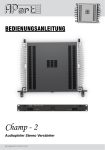
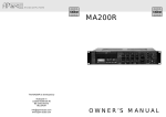
MANUAL
Champ - 2
Audiophile Stereo Power Amplifier
[email protected]
Safety First!
•
•
•
•
•
•
•
•
•
•
•
•
•
•
•
•
•
•
•
•
•
Caution: hot and sharp surfaces ! This professional device needs to be installed by
qualified personnel only.
Please check the carton box for any kind of damage on reception of the goods. In case of a
damaged carton, please contact your dealer before opening the carton.
!!!! Danger !!!! Exposure to extremely high noise levels may cause a permanent hearing
loss. Individuals vary considerably to noise induced hearing loss but nearly everyone will lose
somehearingifexposedtosufficientlyintensenoiseforasufficientamountoftime.Therefore
it is recommended that all persons exposed to equipment capable of producing high sound
pressurelevels,suchasthisamplifier,beprotectedbyhearingprotectionwhileinstallingor
operating this unit.
Read all documentation before operating your equipment.
Keep all documentation for future reference.
Save the carton and packing material even if the equipment has arrived in good condition.
Should you ever need to ship the unit, use only the original factory packing.
Do not spill water or other liquids into or on the unit.
Make sure power outlets conform to the power requirements listed on the back of the unit.
Do not use the unit if the electrical power cord is frayed or broken.
Always operate the unit with the AC ground wire connected to the electrical system ground.
Havegaincontrolsonamplifiersturneddownduringpower-uptopreventspeakerdamageif
there are high signal levels at the inputs.
Donotconnecttheinputs/outputsofamplifiersorconsolestoanyothervoltagesource,such
asabattery,mainssource,orpowersupply,regardlessofwhethertheamplifierorconsoleis
turned on or off.
Power down & disconnect units from mains voltage before making connections.
Do not use the unit near stoves, heat registers, radiators, or other heat producing devices.
Donotoperateequipmentonasurfaceorinanenvironmentwhichmaydistortthenormalflow
of air around the unit. If the unit is used in an extremely dusty or smoky environment, the unit
should be periodically “blown free” of dust.
Do not remove the cover. Removing the cover will expose you to potentially dangerous voltages.
Do not drive the inputs with a signal level higher than that required to drive equipment to full
output.
Donotruntheoutputofanyamplifierbackintoanotherinput.
Do not ground the red output terminal, never connect a red output terminal to another red
output terminal.
Incaseofmal-functionthisdeviceshouldbeservicedbyqualifiedservicepersonnelonly.
2
WWW.APART-AUDIO.COM
Introduction
Dear customer,
Whydoeslivemusicleaveanunforgettableimpressiononyou?Theanswerissimple:dynamics.
Theabilityofasoundsystemtoproducecrystalclearlowlevelsoundsaswellasextreme
musical peaks without any distortion, the power to leave some headroom for those occasional
peaksinmusic.Purepower!Thiseaseofmusicreproductioncannotbedescribedinfiguresor
specifications.
In the following pages we will explain how we have reached our goal. Champ-2 features an
exceptionallydynamicoutputstage,auniqueclassGamplifier,allpackedinaoneunitfanless
enclosure. While our competitors are struggling with often poorly designed so called energy
efficientclassDdigitalamplifiers…well,wehavetakenacloselookandlistenedcarefullytosome
of these designs, and we were not impressed. We got inspired to make something APart from all
the rest, and started from scratch.
Takealookatournewchampionwithhisstrikingdesignandpowerfulsetoffeaturesthatwill
exceed the demands of passionate music lovers as well as system integrators. Designed with
a continuous 4 ohm, 2 ohm dynamically stable high current output stage, Champ-2 will surprise
youwithitssonicexcellenceanddynamiccapacities.Remember,thisuniqueamplifierhasbeen
developed with the impact of live music dynamics in mind. A true beauty, inside as well as outside,
but also a beast if necessary.
TakeyourtimeandlistentoournewChamp-2amplifier.Pleasefastenyourseatbeltsandbeware,
you might get blown away, not by the cooling fan, simply because there isn’t any. Experience the
pure musical power of Champ-2.
Manual contents
1. Fanless design and highlights
2. Features
3. Inputs and outputs
4. Rack mounting and wiring
5. Standalone use
6. Technical specifications
3
[email protected]
1. Fanless design and highlights
•
Audiophile grade components mounted on solid aluminum and steel construction chassis for
thehighestpossiblesignalintegrityandreliability,evenunderdifficultcircumstances.
•
ighcurrent,highvoltagediscreteoutputstageinclassGconfiguration,capableofdriving
H
even the most demanding speaker systems and combinations. Either at low or high power, you
will hear the Champ-2 difference.
•
ustomdesignedsidemountheatsinks,incombinationwithclassGamplifiertopologyhave
C
madeitpossibletocreateadiscretehighpoweramplifierwithouttheneedofanoisydustcollectingcoolingfaninsidetheenclosure.Thismeanslessmaintenance,noannualfanordust
filterexchangeprocedure,nomoreamplifiercleanout…no unwanted noise from cooling
fans, Champ-2 relies on convectional cooling only, a unique feature in this output power class,
and all packed in a 1 unit 19 inch case!
•
IntegratedAPClimitercircuitryandcliplimiteradaptabletotheactualspeakerload.Thisintelligent circuit will prevent harsh distortion caused by clipping, provided that the input signal itself
isnotdistortedofcourse…whatgoesin,comesout.
•
A stunning 38800 µF of high grade electrolytic capacitors, high power toroidal transformer for
ultimate power reserve.
•
elf-supportinglowresonancesteelsubframe.Torsionfreefrontandsidepanelconstruction
S
with integrated heatsink assembly.
•
Solid aluminum brushed front panel with removable 19” brackets and handles for use in a rack
or as a standalone unit in high quality audio systems.
•
ultipurposeinputconfigurationfeaturingbalancedinputsonXLRconnectorsandunbalanced
M
inputsonRCAconnectors…
4
WWW.APART-AUDIO.COM
2. Features
•
Intelligent APC circuitry constantly analyses incoming music signals and keeps dynamics
alive.Anadditionalultrafastpeaklimiteravoidsamplifierclippingincasesomeonehitsthe
inputstoohard.Pleaseremember,thisisamusicalamplifier,pleaseleavesomeheadroom
and enjoy the music.
•
ridgeorstereomode:morethandoubletheoutputpowerandconvertthisamplifierintoa
B
monoblockamplifierwithonepushonabutton.Minimum load impedance is 8 ohms in
bridge mode.
•
rotectioncircuitry:theprotectioncircuitryisanotheruniquedesignfeatureofthisampliP
fier:togetherwiththeAPCcircuitry,outputsignalsareconstantlymonitoredbytheprotection
circuits, and speaker outputs will be cut in case of extreme overload, short circuits, DC offset,
overheating…Thiscircuitisalsocapable(withincertainlimits)ofreducingtheinputsignalto
prevent clipping, distortion and other musically destructive situations. We have done our best to
makesurethisamplifierwillproducecleanpower,butit is also the user who is responsible
for the final result: the APC circuitry can not clean up a clipped input signal, in other
words: what goes in, comes out. Don’t forget to set the impedance selector correctly for
both channels and remember to divide the speaker’s impedance by a factor 2 if you are
planning to use the amplifier in bridge mode ! Example in bridge mode: speaker load = 8
ohms, set channel 1 impedance selector to 8 : 2 = 4 ohms setting (4 – 8 ohms).
•
ersatileinputandoutputconnectorconfigurationwithbalancedandunbalancedinputsand
V
additionallinelevelsignaloutputsforlinkingthesignaltootherdevicesforincreasedflexibility.
Thespeakeroutputterminalsacceptspeakercablesaswellas4mmbananaplugs.
•
roundliftswitchtoenableyoutofindthecauseofsystemgroundloopsincaseofhumor
G
excessive noise.
5
[email protected]
What is APC ?
APC is one of the most intelligent amplifier protection circuits ever designed, simply
because it does the job without interfering with the typical dynamic character of
music. APC allows you to fully exploit the potential of the amplifier, maintaining high
power reserves and thus producing high, clean power.
It is a common misunderstanding that high power amplifiers will overload or destroy
lower power speakers, the opposite is true. You can easily destroy a 500 Watt rated
speaker with a simple 50 watt power amplifier ! Why ? In order to produce a low tone,
such as a kick drum or bass guitar, you need about 80 % or more of an amplifier’s
power. Because distortion is less audible in low frequencies, you would want to
increase the level more than the amplifier can supply. This causes low frequency
distortion which causes high frequency harmonics. These harmonics contain more
high frequency energy than the high frequency speaker can deal with. Result: harsh
distortion and sudden heat rise in the high frequency speaker’s voice coil. After a
short while, the high power speaker may burn out.
Conclusion: don’t punish your speakers with weak amplifiers. Set the APC control
to a power level equal to your speaker’s RMS input power and avoid hitting the clip
limiter !
6
WWW.APART-AUDIO.COM
3. Inputs and outputs
Frontpanellayout:
1
2
3
4
5
6
7
8
9 10 11 12
1)Volumepotmeterchannel1:usethispotmetertopresetthevolume.Incasetheamplifierhas
been switched to bridge mode, this potmeter sets the level for bridge operation.
2)Signalledchannel1:thisledlightsupgreenwhenasufficientlystrongsignalispresentonthe
left channel, after passing the input level control. At startup, the led will light up red during a
few seconds, this is perfectly normal. When it lights up red during use, the power transformer
orpoweramplifierisoverheatedorinprotectmodeandisshutdown.Turnoffthepower.The
amplifier will not turn on automatically after most error conditions. In some cases, the
user MUST turn off power and remove the overload and then power on again ! More
details can be found in the table below.
3)APCactivityledleftchannel:thisledlightsupwhentheAPCcircuitryisactive.TheAPC
circuitry reduces the gain at the inputs to guarantee the full dynamic range of the power
amplifiercircuits.
4)Clipledchannel1:thisledlightsupwhenevertheamplifierclips.Thisisawarningsign:you
are pushing things a little too far or you are overloading the amp. Reduce the input level by a
few dB so that this led never lights up anymore ! Don’t ignore this!
5)Templedleftchannel:thisledlightsupwhentheamplifierisoverheated.Outputpower
willautomaticallybecutbytheAPCcircuitry.Thispartoftheprotectioncircuitresetsitself
automaticallywhentemperaturehasnormalized.Whenbothsignalled(2)andtempled(5)are
red,thepowertransformer’sthermalprotectionisactiveandtheamplifierisshutdown.Turn
off the power and let it cool down. The amplifier will not turn on automatically after the
transformer has cooled down, the user MUST turn off the power, remove the cause of
the fault condition, wait for cooling down and then power on again!
6)Bridgeled:thisledlightsuptoindicatethattheamplifierisinbridgemode.
7)Powerswitchandpowerled:fliptheswitchtopowerontheamplifier.Theblueledwilllightup
to indicate that mains power is present.
7
[email protected]
8) Signalledchannel2:thisledlightsupgreenwhenasufficientlystrongsignalispresent
on the left channel, after passing the input level control. At startup, the led will light up red
during a few seconds, this is perfectly normal. When it lights up red during use, the power
transformerorpoweramplifierisoverheatedorinprotectmodeandisshutdown.Turnoffthe
power. The amplifier will not turn on automatically after most error conditions. In some
cases, the user MUST turn off power and remove the overload and then power on
again ! More details can be found in the table below.
9) APCactivityledrightchannel:thisledlightsupwhentheAPCcircuitryisactive.TheAPC
circuitry reduces the gain at the inputs to guarantee the full dynamic range of the power
amplifiercircuits.
10)Clipledchannel2:thisledlightsupwhenevertheamplifierclips.Thisisawarningsign:you
are pushing things a little too far or you are overloading the amp. Reduce the input level by a
few dB so that this led never lights up anymore ! Don’t ignore this !
11)Templedleftchannel:thisledlightsupwhentheamplifierisabouttooverheat.Outputpower
willautomaticallybelimitedbytheAPCcircuitrytoavoidfurtheroverheating.Thispartofthe
protection circuit resets itself automatically when temperature has normalized. When both
signalled(2)andtempled(5)arered,thepowertransformer’sthermalprotectionisactive
andtheamplifierisshutdown.Turnoffthepowerandletitcooldown. The amplifier will not
turn on automatically after it has cooled down, the user MUST turn off power, wait for
cooling down and then power on again ! More details can be found in the table below.
12)Volumepotmeterchannel2:usethispotmetertopresetthevolume.Inbridgemode,this
potmeter has no function.
8
WWW.APART-AUDIO.COM
Led status messages
Fault
condition
SGL led CH1
= red
Ch 1 amp
overheat
TEMP led CH1
= red
SGL led CH2
= red
Yes
Ch 2 amp
overheat
Ch 1 amp
error (DC,
HF, short
circuit,
overload)
Yes
Yes
Yes
Ch 2 amp
error (DC,
HF, short
circuit,
overload)
Transformer
thermal
protection
TEMP led CH2
= red
Yes
Yes
Yes
Yes
What to do ?
Output signal
condition
Reduce input
signal or check
amplifierload.
Wait for cool
down.
No output
Reduce input
signal or check
amplifierload.
Wait for cool
down.
No output
Switch off power
and remove
error.Leave
switched off
for at least 10
seconds. Switch
power on.
No output
Switch off power
and remove
error.Leave
switched off
for at least 10
seconds. Switch
power on.
No output
Switch off power
and wait for cool
down*.
No output
*In case the transformer is overheated, it may take a long time before the amplifier has cooled
down sufficiently. In such cases, you may have overloaded the amplifier too much. Power off the
amplifier immediately, correct the error and wait until the amplifier has cooled down.
Under normal circumstances, this amplifier will not overheat. If any of the above
mentioned overheating situations occur, please check the load impedance, the
ventilation and last but not least, input levels. The intelligent APC circuitry will
reduce input gain and level to a safe margin within certain limits. This circuitry can
not correct an input signal that is already clipped and distorted.
9
[email protected]
Rearpanellayout:
1
2
3
4
5
6
7
8
9 10 11
12
13
1)Channel2unbalancedinputoncinchconnectors:usethetoporbottomcinchconnectorto
applyanunbalancedsignalonchannel2.Theseconnectorsarewiredinparallel,thismeans
you can use the second connector as a signal link connector.
2)Channel2balancedinputonNeutrikXLRconnector,thisconnectoriswiredinparallelto
connector‘3’.Thisallowsyoutolinkthebalancedsignaltoanotheramplifier.
3)Channel2balancedinputonNeutrikXLRconnector,thisconnectoriswiredinparallelto
connector‘2’.Thisallowsyoutolinkthebalancedsignaltoanotheramplifier.
4)Groundliftswitch:usethisswitchtoliftorconnectaudiogroundtosafetyground.Thiscanbe
usefull in case of hum.
5)Speakerloadimpedanceselectorchannel2:setthisselectorcorrectlyaccordingtothe
actualloadimpedance.For4to8ohmsapplications:switchisnotpushedin.For2to3
ohmapplications:pushthebuttonin.Pleasenotethattheimpedancementionedisthetotal
loadoftheamplifierchannel,thismeansthatifyouconnectforexample3speakerswith8
ohmimpedance,youMUSTpushthebuttoninbecausetheloadontheamplifieris8:3=
2.7 ohms. In case of bridge operation this button has no function. Use channel 1 impedance
selector in case of bridge operation.
6)Channel2speakerbindingpost:thisconnectoracceptsspeakercableaswellas4mm
banana plugs. Remove the protective cover from the middle of the red/black binding post in
caseyouwanttousebananaplugs.Forbridgemodeapplications,youMUSTusethered
bindingpostsonly:channel2redplugisbridgemodenegativespeakerconnector.
7)Mainscableconnector:plugthemainscableconnectorhere,thissocketalsocontainsamains
fuseholder.Replacethisfuseonlywitha3AT250Vtype.
8)Channel1speakerbindingpost:thisconnectoracceptsspeakercableaswellas4mm
banana plugs. Remove the protective cover from the middle of the red/black binding post in
caseyouwanttousebananaplugs.Forbridgemodeapplications,youMUSTusethered
bindingpostsonly:channel1redplugisbridgemodepositivespeakerconnector.
10
WWW.APART-AUDIO.COM
9)Bridgemodeswitch:usethisswitchtoconverttheamplifierintoamonobridgeamplifier.In
thiscaseyoucanapplyaninputsignaltothechannel1inputonly!Leavethechannel2
connectors open ! Bridge mode input level is controlled by the channel 1 volume controller
only.The‘BR’ledonthefrontpanelwillindicatethattheamplifierisinbridgemode.Minimum
bridgemodespeakerloadis8ohms.Neverusethespeakeroutput–(minus)connectorsin
bridge mode !
10)Speakerloadimpedanceselectorchannel1:setthisselectorcorrectlyaccordingtothe
actualloadimpedance.For4to8ohmsapplications:switchisnotpushedin.For2to3
ohmapplications:pushthebuttonin.Pleasenotethattheimpedancementionedisthetotal
loadoftheamplifierchannel,thismeansthatifyouconnectforexample3speakerswith8
ohmimpedance,youMUSTpushthebuttoninbecausetheloadontheamplifieris8:3=
2.7 ohms. Use channel 1 impedance selector in case of bridge operation. In case of bridge
operationthisswitchmustbeputto4-8ohmoperationbecausetheminimumloadimpedance
inbridgemodeis8ohm.Lessthan8ohmsinbridgemodeisnotallowed!
11)Channel1balancedinputonNeutrikXLRconnector,thisconnectoriswiredinparallelto
connector‘12’.Thisallowsyoutolinkthebalancedsignaltoanotheramplifier.
12)Channel1balancedinputonNeutrikXLRconnector,thisconnectoriswiredinparallelto
connector‘11’.Thisallowsyoutolinkthebalancedsignaltoanotheramplifier.
13)Channel1unbalancedinputoncinchconnectors:usethetoporbottomcinchconnectorto
applyanunbalancedsignalonchannel1.Theseconnectorsarewiredinparallel,thismeans
you can use the second connector as a signal link connector.
What is bridge mode ?
In bridge mode, you can unite the power of 2 small amplifiers into 1 giant amp.
The resulting power usually is more than double the power of both amplifiers used
individually with the same load. There is a simple reason for this power boost:
because the speaker load is wired to the channel’s positive (hot) connectors, the
amplifiers ‘feel’ half of the actual speaker’s impedance. This means that, despite
the fact that you connect for example an 8 ohm speaker, the amp thinks there is a 4
ohm load, resulting in higher power output per amplifier, and since both amplifiers
work in bridge mode, this increased power is doubled. As a result, the minimum load
impedance in bridge mode is limited to 8 ohms, because every amplifier only ‘feels’
half of this impedance. Set the speaker impedance selector of channel 1 to the 4-8
ohms position for 8 ohms(or higher) loads in bridge mode.
11
[email protected]
4. Rack mounting and wiring
Champ-2canbemountedina19”rack,takinguponly1rackspace.Alwaysallowagoodairflow
aroundtheamplifier’sfront,rear,side,topandbottom.Wheninstallinginarackwithmultipleaudio
devices, it is compulsory to leave one rack space between units. Fill the empty rack spaces with
meshedblindpanelsforimprovedventilation.Nevermounttheamplifierinasealedcabinet,unless
adequateforcedventilationisprovided.Theamplifiermaynotbeabletomeetthespecifications
when installed in a poorly ventilated environment. Support the unit at the rear when installing in a
rack !
Always remember: excessive heat is one of your amplifier’s biggest enemies !
When wiring an audio rack, it is a good installation practice to route all AC wiring
along one side of the rack and all audio wiring along the other side to avoid coupling
mains cable interference into the audio path. Please use only high quality signal
and speaker cables and connectors. Pay special attention to avoiding ground loops
when installing audio devices in metal racks, use special insulating rack mounting
hardware, such as the so called ‘humfrees’. This mounting hardware will make sure
that several devices mounted in a rack will be electrically isolated from the rack, and
thus are a great help in avoiding ground loops. Any damage caused by user induced
ground loops are not covered by warranty ! Ground loops can cause hum or other
strange side effects that will affect stable and safe operation of audio hardware and
peripheral devices. Ground loops are often created by connecting tuners to cable
distribution sockets. Use a RF isolating transformer whenever there is a cable signal
tuner or digital TV tuner in the audio path !
12
WWW.APART-AUDIO.COM
5. Standalone use
ItispossibletointegrateChamp-2inahighqualityaudiochain.Inordertoadaptthefrontpanel
dimensions to the dimensions of other equipment, it is possible to remove the 19” brackets and
handlesforanevenmoresleekandrefinedlook.
Remove the two screws marked in red circles and slide off the handles.
13
[email protected]
6. Technical specifications
Rated output power, both channels driven:
Dynamic program power, both channels driven
Bridge-monooperation8ohm
750 W
2 channel mode 8 ohm
200 W / ch
2 channel mode 4 ohm
350 W / ch
2 channel mode 2.7 ohm
450 W / ch
Dynamic capacity at 2 ohm, both channels
driven
600 W / ch
*a 2.7 ohm load can be seen as 3 pieces of 8 ohm speakers in parallel (or even 6 pcs of 16 ohm speakers).
A 2 ohm load is technically possible but not recommended for long term use at high power.
Sine wave power, both channels driven (not recommended, for reference only)
This amplifier is designed for an audiophile music experience, not for lab testing!
Bridge-mono operation 8 ohm
350 W
2 channel mode 8 ohm
120 W / ch
2 channel mode 4 ohm
180 W / ch
2 channel mode 2.7 ohm
200 W / ch
14
WWW.APART-AUDIO.COM
General technical specifications
Input impedance / sensitivity unbalanced
(RCA)/4ohm
10 Kohm / 1 V 0dBV
Inputimpedance/sensitivitybalanced(XLR)
/ 4 ohm
20 Kohm / 1 V 0 dBV
Frequencyresponse(0,-0.5dB)
10 Hz – 50 kHz
THD
< 0.05 %
IMD
< 0.06 %
Noise
>100 DBA
Gain
30dB(36dBbridged)
Damping factor
> 200
Dynamics and level control
APC,switchablefor2-3or4-8ohms
Power amp circuit design
High current, high voltage class G
Efficiency(dynamicprogramof10dB,1V
input)
70 %
Protection circuits
DC,HF,clip,overcurrent,short-circuit
Temperatureprotection
95°C/ch + transformer 105°C
Cooling
convectional, no fan
Power consumption
15VA idle, 600VA full program, 1KVA peak
Mains power requirements
230VAC, 50Hz
Physical specifications
Netdimensions(cm)(WxHxD)
48.3X4.4X36
Grossdimensions(cm)(WxHxD)
56 x 10 x 55
Net weight
7.5 kg
Gross weight
9.0 kg
APart-Audio general warranty conditions:
APart-Audio warrants this product to be free of defects in material and workmanship for a period of one* year for parts and for a
period of one* year for labor from the date of original end-user purchase. This warranty is valid only for the original end-user and
cannot be transferred.
During the warranty period APart-Audio orone of its authorized service partners shall either repair or replace any product, free of
charge, that proves to be defective on inspection by APart-Audio or its authorized service representative.
15
[email protected]
ANY SUGGESTION?
They are well appreciated and eventually rewarded!
Send your ideas or suggestions to
[email protected]
Company names, product names, and names of formats etc. are the trademarks or registered trademarks of
their respective owners.
© 2008 APart-Audio specifications subject to change without notice.
CHAMP-2 is developed by
Audioprof nv
Lanteernhofstraat 90
BE-2100 Deurne
BELGIUM
16
WWW.APART-AUDIO.COM