1
Junos Pulse Secure Access Service
SA Series 4500, 6500, and FIPS Appliances
Release
7.2
Published: 2012-05-15
Copyright © 2012, Juniper Networks, Inc.
Juniper Networks, Inc.
1194 North Mathilda Avenue
Sunnyvale, California 94089
USA
408-745-2000
www.juniper.net
Copyright © 2012, Juniper Networks, Inc. All rights reserved.
Juniper Networks, Junos, Steel-Belted Radius, NetScreen, and ScreenOS are registered trademarks of Juniper Networks, Inc. in the United
States and other countries. The Juniper Networks Logo, the Junos logo, and JunosE are trademarks of Juniper Networks, Inc. All other
trademarks, service marks, registered trademarks, or registered service marks are the property of their respective owners.
Juniper Networks assumes no responsibility for any inaccuracies in this document. Juniper Networks reserves the right to change, modify,
transfer, or otherwise revise this publication without notice.
Products made or sold by Juniper Networks or components thereof might be covered by one or more of the following patents that are
owned by or licensed to Juniper Networks: U.S. Patent Nos. 5,473,599, 5,905,725, 5,909,440, 6,192,051, 6,333,650, 6,359,479, 6,406,312,
6,429,706, 6,459,579, 6,493,347, 6,538,518, 6,538,899, 6,552,918, 6,567,902, 6,578,186, and 6,590,785.
Junos Pulse Secure Access Service SA Series 4500, 6500, and FIPS Appliances
Release 7.2
Copyright © 2012, Juniper Networks, Inc.
All rights reserved.
The information in this document is current as of the date on the title page.
YEAR 2000 NOTICE
Juniper Networks hardware and software products are Year 2000 compliant. Junos OS has no known time-related limitations through the
year 2038. However, the NTP application is known to have some difficulty in the year 2036.
END USER LICENSE AGREEMENT
The Juniper Networks product that is the subject of this technical documentation consists of (or is intended for use with) Juniper Networks
software. Use of such software is subject to the terms and conditions of the End User License Agreement (“EULA”) posted at
http://www.juniper.net/support/eula.html. By downloading, installing or using such software, you agree to the terms and conditions
of that EULA.
ii
Copyright © 2012, Juniper Networks, Inc.
Table of Contents
About the Documentation . . . . . . . . . . . . . . . . . . . . . . . . . . . . . . . . . . . . . . . . . . . . vii
Documentation and Release Notes . . . . . . . . . . . . . . . . . . . . . . . . . . . . . . . . . vii
Supported Platforms . . . . . . . . . . . . . . . . . . . . . . . . . . . . . . . . . . . . . . . . . . . . . vii
Documentation Conventions . . . . . . . . . . . . . . . . . . . . . . . . . . . . . . . . . . . . . . vii
Documentation Feedback . . . . . . . . . . . . . . . . . . . . . . . . . . . . . . . . . . . . . . . . . ix
Requesting Technical Support . . . . . . . . . . . . . . . . . . . . . . . . . . . . . . . . . . . . . . ix
Self-Help Online Tools and Resources . . . . . . . . . . . . . . . . . . . . . . . . . . . . . . . . x
Opening a Case with JTAC . . . . . . . . . . . . . . . . . . . . . . . . . . . . . . . . . . . . . . . . . x
Part 1
Overview
Chapter 1
Appliances . . . . . . . . . . . . . . . . . . . . . . . . . . . . . . . . . . . . . . . . . . . . . . . . . . . . . . . . 3
SA4500 and SA6500 . . . . . . . . . . . . . . . . . . . . . . . . . . . . . . . . . . . . . . . . . . . . . . . . 3
Standard Hardware . . . . . . . . . . . . . . . . . . . . . . . . . . . . . . . . . . . . . . . . . . . . . . . 3
SA Series 6500 Field-Replaceable Units . . . . . . . . . . . . . . . . . . . . . . . . . . . . . . 4
Chapter 2
FIPS . . . . . . . . . . . . . . . . . . . . . . . . . . . . . . . . . . . . . . . . . . . . . . . . . . . . . . . . . . . . . . 7
SA FIPS . . . . . . . . . . . . . . . . . . . . . . . . . . . . . . . . . . . . . . . . . . . . . . . . . . . . . . . . . . . . 7
SA FIPS Execution . . . . . . . . . . . . . . . . . . . . . . . . . . . . . . . . . . . . . . . . . . . . . . . . . . . 8
FIPS Overview . . . . . . . . . . . . . . . . . . . . . . . . . . . . . . . . . . . . . . . . . . . . . . . . . . . . . . 9
Part 2
Planning
Chapter 3
Network Preparation . . . . . . . . . . . . . . . . . . . . . . . . . . . . . . . . . . . . . . . . . . . . . . . 13
Secure Access Appliances . . . . . . . . . . . . . . . . . . . . . . . . . . . . . . . . . . . . . . . . . . . . 13
Chapter 4
Name and Password Restrictions . . . . . . . . . . . . . . . . . . . . . . . . . . . . . . . . . . . . 15
Name and Password Restrictions . . . . . . . . . . . . . . . . . . . . . . . . . . . . . . . . . . . . . . 15
Chapter 5
Security World . . . . . . . . . . . . . . . . . . . . . . . . . . . . . . . . . . . . . . . . . . . . . . . . . . . . . 17
Creating a New Security World . . . . . . . . . . . . . . . . . . . . . . . . . . . . . . . . . . . . . . . . . 17
Recovering an Archived Security World . . . . . . . . . . . . . . . . . . . . . . . . . . . . . . . . . . 20
Part 3
Installation
Chapter 6
Hardware . . . . . . . . . . . . . . . . . . . . . . . . . . . . . . . . . . . . . . . . . . . . . . . . . . . . . . . . 25
Installing Secure Access Appliance Hardware . . . . . . . . . . . . . . . . . . . . . . . . . . . . 25
Chapter 7
Clusters . . . . . . . . . . . . . . . . . . . . . . . . . . . . . . . . . . . . . . . . . . . . . . . . . . . . . . . . . . 27
Joining a Cluster . . . . . . . . . . . . . . . . . . . . . . . . . . . . . . . . . . . . . . . . . . . . . . . . . . . . 27
Deploying a Cluster in a Secure Access FIPS Environment . . . . . . . . . . . . . . . . . . 28
Copyright © 2012, Juniper Networks, Inc.
iii
SA Series 4500, 6500, and FIPS Appliances
Chapter 8
Keystores . . . . . . . . . . . . . . . . . . . . . . . . . . . . . . . . . . . . . . . . . . . . . . . . . . . . . . . . . 31
Initializing a Keystore . . . . . . . . . . . . . . . . . . . . . . . . . . . . . . . . . . . . . . . . . . . . . . . . . 31
Reinitializing the Keystore . . . . . . . . . . . . . . . . . . . . . . . . . . . . . . . . . . . . . . . . . . . . . 31
Binary Importing and Exporting of the Keystore . . . . . . . . . . . . . . . . . . . . . . . . . . . 32
Chapter 9
Device Certificates . . . . . . . . . . . . . . . . . . . . . . . . . . . . . . . . . . . . . . . . . . . . . . . . 35
Importing Device Certificates . . . . . . . . . . . . . . . . . . . . . . . . . . . . . . . . . . . . . . . . . . 35
Chapter 10
Initial Configuration . . . . . . . . . . . . . . . . . . . . . . . . . . . . . . . . . . . . . . . . . . . . . . . 37
Basic Setup for Secure Access Appliances . . . . . . . . . . . . . . . . . . . . . . . . . . . . . . . 37
Licensing and Configuring Your Secure Access . . . . . . . . . . . . . . . . . . . . . . . . . . . . 39
Part 4
Maintenance
Chapter 11
Hardware Replacement . . . . . . . . . . . . . . . . . . . . . . . . . . . . . . . . . . . . . . . . . . . . 43
Replacing the Cooling Fans . . . . . . . . . . . . . . . . . . . . . . . . . . . . . . . . . . . . . . . . . . . 43
Replacing a Hard Drive . . . . . . . . . . . . . . . . . . . . . . . . . . . . . . . . . . . . . . . . . . . . . . . 44
Replacing IOC Modules . . . . . . . . . . . . . . . . . . . . . . . . . . . . . . . . . . . . . . . . . . . . . . 44
Replacing a Power Supply . . . . . . . . . . . . . . . . . . . . . . . . . . . . . . . . . . . . . . . . . . . . 46
Chapter 12
LED Behavior . . . . . . . . . . . . . . . . . . . . . . . . . . . . . . . . . . . . . . . . . . . . . . . . . . . . . 49
Device Status LED Behavior . . . . . . . . . . . . . . . . . . . . . . . . . . . . . . . . . . . . . . . . . . 49
Ethernet Port LED Behavior . . . . . . . . . . . . . . . . . . . . . . . . . . . . . . . . . . . . . . . . . . . 50
FIPS Device Status LED Behavior . . . . . . . . . . . . . . . . . . . . . . . . . . . . . . . . . . . . . . . 51
Chapter 13
Passwords . . . . . . . . . . . . . . . . . . . . . . . . . . . . . . . . . . . . . . . . . . . . . . . . . . . . . . . 53
Changing the Security Officer Password . . . . . . . . . . . . . . . . . . . . . . . . . . . . . . . . . 53
Changing the Web User Password . . . . . . . . . . . . . . . . . . . . . . . . . . . . . . . . . . . . . 54
Chapter 14
HSM Firmware . . . . . . . . . . . . . . . . . . . . . . . . . . . . . . . . . . . . . . . . . . . . . . . . . . . . 55
Upgrading the HSM Firmware . . . . . . . . . . . . . . . . . . . . . . . . . . . . . . . . . . . . . . . . . 55
Chapter 15
Administrator Cards . . . . . . . . . . . . . . . . . . . . . . . . . . . . . . . . . . . . . . . . . . . . . . . 57
Creating Administrator Cards . . . . . . . . . . . . . . . . . . . . . . . . . . . . . . . . . . . . . . . . . . 57
Part 5
Troubleshooting
Chapter 16
HSM Card . . . . . . . . . . . . . . . . . . . . . . . . . . . . . . . . . . . . . . . . . . . . . . . . . . . . . . . . 61
Resetting the HSM Card In Case Of An Error . . . . . . . . . . . . . . . . . . . . . . . . . . . . . . 61
Part 6
Index
Index . . . . . . . . . . . . . . . . . . . . . . . . . . . . . . . . . . . . . . . . . . . . . . . . . . . . . . . . . 65
iv
Copyright © 2012, Juniper Networks, Inc.
List of Tables
About the Documentation . . . . . . . . . . . . . . . . . . . . . . . . . . . . . . . . . . . . . . . . . . vii
Table 1: Notice Icons . . . . . . . . . . . . . . . . . . . . . . . . . . . . . . . . . . . . . . . . . . . . . . . . . viii
Table 2: Text and Syntax Conventions . . . . . . . . . . . . . . . . . . . . . . . . . . . . . . . . . . . viii
Part 2
Planning
Chapter 4
Name and Password Restrictions . . . . . . . . . . . . . . . . . . . . . . . . . . . . . . . . . . . . 15
Table 3: Security Officer Name and Username Requirements . . . . . . . . . . . . . . . . 15
Part 3
Installation
Chapter 10
Initial Configuration . . . . . . . . . . . . . . . . . . . . . . . . . . . . . . . . . . . . . . . . . . . . . . . 37
Table 4: Security Requirements . . . . . . . . . . . . . . . . . . . . . . . . . . . . . . . . . . . . . . . . 38
Part 4
Maintenance
Chapter 12
LED Behavior . . . . . . . . . . . . . . . . . . . . . . . . . . . . . . . . . . . . . . . . . . . . . . . . . . . . . 49
Table 5: Device Status LEDs . . . . . . . . . . . . . . . . . . . . . . . . . . . . . . . . . . . . . . . . . . 49
Table 6: 4-Port Copper Gigabit Ethernet LEDs (available on IC4500 and
IC6500) . . . . . . . . . . . . . . . . . . . . . . . . . . . . . . . . . . . . . . . . . . . . . . . . . . . . . . 50
Table 7: Status LED . . . . . . . . . . . . . . . . . . . . . . . . . . . . . . . . . . . . . . . . . . . . . . . . . . 51
Copyright © 2012, Juniper Networks, Inc.
v
SA Series 4500, 6500, and FIPS Appliances
vi
Copyright © 2012, Juniper Networks, Inc.
About the Documentation
•
Documentation and Release Notes on page vii
•
Supported Platforms on page vii
•
Documentation Conventions on page vii
•
Documentation Feedback on page ix
•
Requesting Technical Support on page ix
Documentation and Release Notes
®
To obtain the most current version of all Juniper Networks technical documentation,
see the product documentation page on the Juniper Networks website at
http://www.juniper.net/techpubs/.
If the information in the latest release notes differs from the information in the
documentation, follow the product Release Notes.
Juniper Networks Books publishes books by Juniper Networks engineers and subject
matter experts. These books go beyond the technical documentation to explore the
nuances of network architecture, deployment, and administration. The current list can
be viewed at http://www.juniper.net/books .
Supported Platforms
For the features described in this document, the following platforms are supported:
•
SA6500 FIPS
•
SA4500 FIPS
•
SA6500
•
SA4500
Documentation Conventions
Table 1 on page viii defines notice icons used in this guide.
Copyright © 2012, Juniper Networks, Inc.
vii
SA Series 4500, 6500, and FIPS Appliances
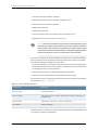
Table 1: Notice Icons
Icon
Meaning
Description
Informational note
Indicates important features or instructions.
Caution
Indicates a situation that might result in loss of data or hardware damage.
Warning
Alerts you to the risk of personal injury or death.
Laser warning
Alerts you to the risk of personal injury from a laser.
Table 2 on page viii defines the text and syntax conventions used in this guide.
Table 2: Text and Syntax Conventions
Convention
Description
Examples
Bold text like this
Represents text that you type.
To enter configuration mode, type
theconfigure command:
user@host> configure
Fixed-width text like this
Italic text like this
Italic text like this
Text like this
< > (angle brackets)
viii
Represents output that appears on the
terminal screen.
user@host> show chassis alarms
•
Introduces or emphasizes important
new terms.
•
•
Identifies book names.
A policy term is a named structure
that defines match conditions and
actions.
•
Identifies RFC and Internet draft titles.
•
Junos OS System Basics Configuration
Guide
•
RFC 1997, BGP Communities Attribute
No alarms currently active
Represents variables (options for which
you substitute a value) in commands or
configuration statements.
Configure the machine’s domain name:
Represents names of configuration
statements, commands, files, and
directories; configuration hierarchy levels;
or labels on routing platform
components.
•
To configure a stub area, include the
stub statement at the[edit protocols
ospf area area-id] hierarchy level.
•
The console port is labeled
CONSOLE.
Enclose optional keywords or variables.
stub <default-metric metric>;
[edit]
root@# set system domain-name
domain-name
Copyright © 2012, Juniper Networks, Inc.
About the Documentation
Table 2: Text and Syntax Conventions (continued)
Convention
Description
Examples
| (pipe symbol)
Indicates a choice between the mutually
exclusive keywords or variables on either
side of the symbol. The set of choices is
often enclosed in parentheses for clarity.
broadcast | multicast
# (pound sign)
Indicates a comment specified on the
same line as the configuration statement
to which it applies.
rsvp { # Required for dynamic MPLS
only
[ ] (square brackets)
Enclose a variable for which you can
substitute one or more values.
community name members [
community-ids ]
Indention and braces ( { } )
Identify a level in the configuration
hierarchy.
; (semicolon)
Identifies a leaf statement at a
configuration hierarchy level.
(string1 | string2 | string3)
[edit]
routing-options {
static {
route default {
nexthop address;
retain;
}
}
}
J-Web GUI Conventions
Bold text like this
Represents J-Web graphical user
interface (GUI) items you click or select.
> (bold right angle bracket)
Separates levels in a hierarchy of J-Web
selections.
•
In the Logical Interfaces box, select
All Interfaces.
•
To cancel the configuration, click
Cancel.
In the configuration editor hierarchy,
select Protocols>Ospf.
Documentation Feedback
We encourage you to provide feedback, comments, and suggestions so that we can
improve the documentation. You can send your comments to
[email protected], or fill out the documentation feedback form at
https://www.juniper.net/cgi-bin/docbugreport/ . If you are using e-mail, be sure to include
the following information with your comments:
•
Document or topic name
•
URL or page number
•
Software release version (if applicable)
Requesting Technical Support
Technical product support is available through the Juniper Networks Technical Assistance
Center (JTAC). If you are a customer with an active J-Care or JNASC support contract,
Copyright © 2012, Juniper Networks, Inc.
ix
SA Series 4500, 6500, and FIPS Appliances
or are covered under warranty, and need post-sales technical support, you can access
our tools and resources online or open a case with JTAC.
•
JTAC policies—For a complete understanding of our JTAC procedures and policies,
review the JTAC User Guide located at
http://www.juniper.net/us/en/local/pdf/resource-guides/7100059-en.pdf .
•
Product warranties—For product warranty information, visit
http://www.juniper.net/support/warranty/ .
•
JTAC hours of operation—The JTAC centers have resources available 24 hours a day,
7 days a week, 365 days a year.
Self-Help Online Tools and Resources
For quick and easy problem resolution, Juniper Networks has designed an online
self-service portal called the Customer Support Center (CSC) that provides you with the
following features:
•
Find CSC offerings: http://www.juniper.net/customers/support/
•
Search for known bugs: http://www2.juniper.net/kb/
•
Find product documentation: http://www.juniper.net/techpubs/
•
Find solutions and answer questions using our Knowledge Base: http://kb.juniper.net/
•
Download the latest versions of software and review release notes:
http://www.juniper.net/customers/csc/software/
•
Search technical bulletins for relevant hardware and software notifications:
https://www.juniper.net/alerts/
•
Join and participate in the Juniper Networks Community Forum:
http://www.juniper.net/company/communities/
•
Open a case online in the CSC Case Management tool: http://www.juniper.net/cm/
To verify service entitlement by product serial number, use our Serial Number Entitlement
(SNE) Tool: https://tools.juniper.net/SerialNumberEntitlementSearch/
Opening a Case with JTAC
You can open a case with JTAC on the Web or by telephone.
•
Use the Case Management tool in the CSC at http://www.juniper.net/cm/ .
•
Call 1-888-314-JTAC (1-888-314-5822 toll-free in the USA, Canada, and Mexico).
For international or direct-dial options in countries without toll-free numbers, see
http://www.juniper.net/support/requesting-support.html .
x
Copyright © 2012, Juniper Networks, Inc.
PART 1
Overview
•
Appliances on page 3
•
FIPS on page 7
Copyright © 2012, Juniper Networks, Inc.
1
SA Series 4500, 6500, and FIPS Appliances
2
Copyright © 2012, Juniper Networks, Inc.
CHAPTER 1
Appliances
•
SA4500 and SA6500 on page 3
SA4500 and SA6500
The SA4500 and SA6500 (SA 4500/6500) are next-generation appliances featuring
a number of notable hardware features.
Standard Hardware
The SA 4500/6500 chassis features the following hardware components:
•
Console port—You use the console port to initially set up the SA 4500/6500 before
you fully integrate it as the secure gateway to your internal network. You can also use
the console port to perform certain configuration and clustering tasks after the Secure
Access Service begins operating as the secure gateway.
•
Bonding ports—By default, on the SA6500 only, the Secure Access Service uses bonding
of the multiple ports to provide failover protection. Bonding two ports on the Secure
Access Service automatically shifts traffic to the secondary port when the primary port
fails.
The SA6500 appliance bonds ports as follows:
•
Internal port = Port 0+Port 1
•
External port = Port 2+Port 3
The Secure Access Service indicates in a message on the System > Network > Overview
page of the administrator admin console whether or not the failover functionality is
enabled.
Copyright © 2012, Juniper Networks, Inc.
3
SA Series 4500, 6500, and FIPS Appliances
Bonding ports cannot span separate networks (multi-homed).
•
Management port—The SA6500’s management port:
•
Enables seamless integration into a dedicated Management Network.
•
Provides continuously available management access to the Secure Access Service.
•
Enables you to perform management activities without impacting user traffic.
•
Allows you to separate administrative access from user access between the Secure
Access Service and Enterprise devices on the internal network.
You can configure the Management port information and advanced settings via the
admin console, just as you would configure the internal port.
•
SFP ports—4-port Small Form-factor Pluggable (SFP) ports are available as an optional
feature for link redundancy to internal switches.
•
Status LEDs—Three device status LEDs are located on the left-side of the front panel
to display power, hard disk access and fault status.
•
Ethernet Port LEDs—The Ethernet port LEDs show the status of each Ethernet port.
The appliance supports up to four node active/active clusters or 2 node active/passive.
SA Series 6500 Field-Replaceable Units
The SA 6500 chassis features three types of field-replaceable units (FRUs) that you can
add or replace. The FRUs are “hot-swappable,” meaning you do not have to first shut
down the SA 6500 before adding or replacing any of the FRUs. The SA4500 has a
“cold-swappable” power supply.
For safety information, refer to the Juniper Networks Products Safety Guide available on
the Juniper Networks Support site.
•
Hard disks—The SA6500 ships with one hard disk, however, you can add an optional
second hard disk to the SA6500 chassis to offer component redundancy and help
minimize the Secure Access Service down time. When a second (redundant) hard disk
is installed, it maintains an exact copy of the software image and configuration
information on the working hard disk. Therefore, if the working hard disk fails, the
redundant hard disk immediately assumes responsibility for all Secure Access Service
operations. This function is referred to as the Redundant Array of Independent Disks
(RAID) mirroring process.
NOTE: The SA6500 hard disk modules are hot-swappable. You must make
sure that the Secure Access Service finishes booting and is operating
correctly before removing, replacing, or upgrading a hard disk module. After
you insert a new hard disk module, you must wait until the RAID mirroring
process is completely finished—which takes approximately 40
minutes—before rebooting or turning off the Secure Access Service.
4
Copyright © 2012, Juniper Networks, Inc.
Chapter 1: Appliances
Related
Documentation
•
Power supplies—The SA6500 ships with one AC power supply installed in the back
of the chassis. You can add an optional second power supply to support redundancy
and load-sharing features. In addition, if you need to replace one of the power supplies,
you can “swap” the faulty power supply for a replacement while the optional second
power supply assumes responsibility for the entire power load, thus avoiding a situation
where you have to power off the Secure Access Service before replacing the removable
unit.
•
Cooling fans—The SA6500 ships with two cooling fans installed in the back of the
chassis. If you need to replace one of the cooling fans, you can “swap” the faulty fan
for a replacement during operation in a matter of moments. You can purchase additional
cooling fans from your vendor when you order your SA6500, or you can purchase them
in the future to replace faulty or failed cooling fans, as necessary, in the future.
•
Device Status LED Behavior on page 49
•
Ethernet Port LED Behavior on page 50
•
Replacing the Cooling Fans on page 43
•
Replacing a Hard Drive on page 44
•
Replacing IOC Modules on page 44
•
Replacing a Power Supply on page 46
Copyright © 2012, Juniper Networks, Inc.
5
SA Series 4500, 6500, and FIPS Appliances
6
Copyright © 2012, Juniper Networks, Inc.
CHAPTER 2
FIPS
•
SA FIPS on page 7
•
SA FIPS Execution on page 8
•
FIPS Overview on page 9
SA FIPS
FIPS, or Federal Information Processing Standards, are National Institute of Standards
and Technology regulations for handling keys and encrypting data. Juniper Networks SA
FIPS is a standard SA4000 or SA6000 NetScreen Instant Virtual Extranet equipped with
a FIPS-certified cryptographic module. The tamper-proof hardware security module
installed on an SA FIPS Series Appliance is certified to meet the FIPS 140-2 level 3 security
benchmark. The module handles private cryptographic key management and SSL
handshakes, simultaneously, ensuring FIPS compliance and off-loading CPU-intensive
public key infrastructure (PKI) tasks from the Secure Access Service to a dedicated
module.
The configuration process for SA FIPS administrators is almost exactly the same as for
the non-SA FIPS administrators, requiring only minor configuration changes during the
initialization, clustering, and certificate generation processes. In the few cases where
administration tasks are different, this guide includes the appropriate instructions for
both SA and SA FIPS administrators. For end-users, SA FIPS is exactly the same as a
standard Secure Access Service system.
SA FIPS is a hardware feature that is built into selected Secure Access Services. It is not
available on SA700 Series Appliances.
Related
Documentation
•
SA FIPS Execution on page 8
•
Creating Administrator Cards on page 57
•
Creating a New Security World on page 17
•
Recovering an Archived Security World on page 20
•
SA FIPS Execution on page 8
Copyright © 2012, Juniper Networks, Inc.
7
SA Series 4500, 6500, and FIPS Appliances
SA FIPS Execution
When you first install a FIPS system, the Secure Access Service serial console walks you
through the process of creating a security world through the serial console. A security
world is a key management system used by SA FIPS consisting of the following elements:
•
Cryptographic module—The cryptographic module (also sometimes called the hardware
security module, or HSM) included with SA FIPS Appliance includes hardware and
firmware installed directly on the appliance. A security world may contain a single
cryptographic module (standard environment) or multiple modules (clustered
environment). However, a single Secure Access FIPS appliance is always equipped
with a single cryptographic module.
•
Security world key—A security world key is a unique Triple DES encrypted key that
protects all other application keys within a security world. As required by the Federal
Information Processing Standards, you cannot import this key into a security world—you
must directly create it from a cryptographic module. In a clustered environment, all of
the modules within the security world share the same security world key.
•
Smart cards—A smart card is a removable key device that looks like a credit card. A
smart card authenticates users, allowing them access to various data and processes
controlled by the cryptographic hardware module. During the initialization process,
you must insert one of your smart cards into the reader (built-in or external, depending
upon which device model you own). As part of the initialization process, the smart card
is transformed into an administrator card that allows the card holder access to the
security world.
•
Encrypted data—Encrypted host data in a Secure Access FIPS environment includes
keys and other data required to share information in a secure manner.
These elements interlock to create a comprehensive security world. When you start the
appliance, it confirms that the security world is valid and that the cryptographic module
is in operational mode before starting normal operations.
You can set the cryptographic module into operational mode using a hardware switch
on the outside of the module. The switch’s settings include:
8
•
I—Initialization mode. Use this setting when initializing the cryptographic module with
a new security world or when adding a module to an existing security world in a Secure
Access cluster. Note that once you set the switch to I and begin initialization, you must
complete the process. Otherwise, your security world is only partially initialized, making
it unusable.
•
O—Operational mode. Use this setting to place the cryptographic module into
operational mode after initialization. Note that you must set the switch to O before
the module powers up in order to alert the unit that you want to begin day-to-day
processing. Otherwise, the module prompts you through the serial console to join the
existing security world or initialize a new one.
•
M—Maintenance mode. In future releases, this setting will be used to upgrade the
firmware on the cryptographic module. (Not yet supported.)
Copyright © 2012, Juniper Networks, Inc.
Chapter 2: FIPS
Related
Documentation
•
SA FIPS on page 7
•
Creating Administrator Cards on page 57
•
Creating a New Security World on page 17
•
Recovering an Archived Security World on page 20
FIPS Overview
The Juniper Networks SA 4500 and 6500 FIPS is a standard SA4500 or SA6500
appliance equipped with a FIPS-compliant crypto card. The tamper-proof hardware
security module installed on a Secure Access FIPS system is certified to meet the FIPS
140-2 level 3 security benchmark.
The configuration process for Secure Access FIPS administrators is almost exactly the
same as for the non-FIPS Secure Access administrators, requiring only minor configuration
changes during the initialization, clustering, and certificate generation processes. In the
few cases where administration tasks are different, this guide includes the appropriate
instructions for both Secure Access and Secure Access FIPS administrators. For end-users,
Secure Access FIPS is exactly the same as a standard Secure Access system.
The FIPS-compliant crypto card is a host bus adapter card that combines IPsec and SSL
cryptographic acceleration with Hardware Security Module (HSM) features. This
combination of a dedicated HSM, advanced cryptographic security and secure key
management meet the security and performance needs for any service.
This card has two main roles: a security officer and a user role. The FIPS-compliant crypto
card replaces the need for administrator cards with the concept of a security officer who
is responsible for key and password management. The security officer credential protects
the keystore from being exported and imported onto another FIPS-compliant crypto
card.
User roles perform cryptographic operations such as accessing keying material within
the keystore as well as performing bulk encryption operations.
The security officer credentials, user credentials, and RSA private keys are stored in the
HSM encrypted keystore located on the Secure Access disk. You are prompted to provide
these credentials whenever any operation requires them. Credentials are not automatically
retrieved from the HSM keystore.
Keystores are stored on the disk and are encrypted with a master key. The master key is
stored in the cryto card firmware and can be backed up by a security officer using a restore
password. This restore password can then be used to restore the master key onto the
same or different FIPS-compliant crypto cards allowing the keystore to be shared across
a cluster, for example.
Related
Documentation
•
Name and Password Restrictions on page 15
•
Initializing a Keystore on page 31
•
Reinitializing the Keystore on page 31
Copyright © 2012, Juniper Networks, Inc.
9
SA Series 4500, 6500, and FIPS Appliances
10
•
Joining a Cluster on page 27
•
Importing Device Certificates on page 35
•
Changing the Security Officer Password on page 53
•
Changing the Web User Password on page 54
•
Resetting the HSM Card In Case Of An Error on page 61
•
Upgrading the HSM Firmware on page 55
•
Binary Importing and Exporting of the Keystore on page 32
Copyright © 2012, Juniper Networks, Inc.
PART 2
Planning
•
Network Preparation on page 13
•
Name and Password Restrictions on page 15
•
Security World on page 17
Copyright © 2012, Juniper Networks, Inc.
11
SA Series 4500, 6500, and FIPS Appliances
12
Copyright © 2012, Juniper Networks, Inc.
CHAPTER 3
Network Preparation
•
Secure Access Appliances on page 13
Secure Access Appliances
Thank you for choosing the Juniper Networks Secure Access Series appliance.
You can install Secure Access and start configuring your system using the following easy
steps:
1.
Install the hardware
2. Perform basic setup
3. License and configure your Secure Access
NOTE: After installing and setting up your Secure Access, refer to the Initial
Configuration task guide in the administrator Web console to install the most
current Secure Access OS service package, license your Secure Access
appliance, and create a test user to verify user accessibility. To test initial set
up and continue configuring your Secure Access, see Getting Started.
We recommend that you install the Secure Access appliance on your LAN to ensure that
it can communicate with the appropriate resources, like authentication servers, DNS
servers, internal Web servers via HTTP/HTTPS, external Web sites via HTTP/HTTPS
(optional), Windows file servers (optional), NFS file servers (optional), and client/server
applications (optional).
NOTE: If you decide to install your Secure Access appliance in your DMZ,
ensure that the Secure Access appliance can connect to these internal
resources.
Related
Documentation
•
Installing Secure Access Appliance Hardware on page 25
•
Basic Setup for Secure Access Appliances on page 37
•
Licensing and Configuring Your Secure Access on page 39
Copyright © 2012, Juniper Networks, Inc.
13
SA Series 4500, 6500, and FIPS Appliances
14
Copyright © 2012, Juniper Networks, Inc.
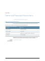
CHAPTER 4
Name and Password Restrictions
•
Name and Password Restrictions on page 15
Name and Password Restrictions
Security officer names and usernames must adhere to the following requirements:
Table 3: Security Officer Name and Username Requirements
Security Officer Name and Username
Requirement
Description
Minimum Length
At least one character
Maximum Length
63 characters
Valid Characters
Alphanumeric, underscore (_), dash (-) and period (.)
First Character
Must be alphabetic
Passwords must be at least six characters and no more than 63 characters. Three
characters must be alphabetic and one character must be non-alphabetic.
Related
Documentation
•
FIPS Overview on page 9
Copyright © 2012, Juniper Networks, Inc.
15
SA Series 4500, 6500, and FIPS Appliances
16
Copyright © 2012, Juniper Networks, Inc.
CHAPTER 5
Security World
•
Creating a New Security World on page 17
•
Recovering an Archived Security World on page 20
Creating a New Security World
You cannot begin using a Secure Access FIPS machine until you create a security world
on it. However, in some case you may need to overwrite that security world with a new
one. For example, if you lose an administrator card, we recommend that you create a
brand new security world to prevent an untrusted source from finding the card and
accessing your security world. You may also need to create a new security world if you
cannot remember your original administrator cards pass phrases.
In order to create a new security world, you must have physical access to:
•
The cryptographic module(s) that belong to the security world.
•
A smart card reader (if you use an older model Secure Access device that does not
contain a built-in card reader).
•
One or more unformatted smart cards or administrator cards containing data that you
can safely overwrite.
NOTE: Your old administrator cards will not work with the new security world
until you reformat them with the new security world’s data. Also note that
once you set the switch to I and begin initialization, you must complete the
process. Otherwise, your security world is only partially initialized, making it
unusable.
WARNING: You must obtain one or more new device certificates from your
CA whenever you create a new security world.
Creating a Security World on a Stand-Alone Secure Access
Copyright © 2012, Juniper Networks, Inc.
17
SA Series 4500, 6500, and FIPS Appliances
To create a new security world on a stand-alone Secure Access:
1.
Insert an un-formatted smart card or an administrator card containing data that you
can safely overwrite into the card slot with the card contacts facing up.
2. Set the mode switch on the cryptographic module to I (initialization mode).
3. Access the Secure Access serial console and reboot the Secure Access device. After
the Secure Access device reboots, you are prompted on the serial console with the
following question: Do you want to use the currently installed security world (y/n)?
4. Perform one of the following:
•
If you want to create a new security world, then:
a. Enter n and press Enter.
b. You are asked to confirm this choice with the prompt "Are you sure you want to
delete your existing Security World (including server certificates) (y/n)?". If you
choose to continue enter y and press Enter.
c. Enter the number of administrator cards you want to create and press Enter.
d. Enter y and press Enter to confirm the number of cards you want to create.
•
If you want to use the currently installed security world, then:
a. Enter y and press Enter.
b. Proceed to the next numbered step in this procedure.
5. Reset the cryptographic module’s mode switch to O (operational mode).
6. Add the common name and company name when prompted. The system uses the
existing self-signed certificate temporarily.
7. Create a new device certificate that shares the new security world’s private key.
WARNING: You must obtain one or more new server certificates from your
CA whenever you create a new security world.
Creating a Security World in a Clustered Environment
To create a new security world in a clustered environment:
1.
Sign in to the admin console of a cluster node. To access a node’s admin console,
enter its internal IP address followed by “/admin” in a browser. For example:
https://x.x.x.x/admin
2. On the System > Clustering > Status tab, select the checkbox for all nodes other than
the current node in the Cluster Members column and then click Disable.
3. Initialize the cluster member with a security world. If this is the first node in the cluster,
create a new security world.
18
Copyright © 2012, Juniper Networks, Inc.
Chapter 5: Security World
4. Return to the node’s System > Clustering > Status tab, select the checkbox next to
disabled nodes in the Cluster Members column, and then click Enable.
5. Wait for all the cluster members to go into an "Enabled" state.
6. Set the mode switch on the cryptographic modules of cluster members that were
earlier disabled to I (initialization mode).
7. Reboot each of these nodes from the serial console.
8. After a node joins the security world, reset its cryptographic module's mode switch
to O (operational mode).
Replacing Administrator Cards
You can replace an administrator card by selecting the Replace Administrator Card Set
option from the serial console. You cannot increase the number of administrator cards
in an existing set. If you want to do this, you have to create a new security world which
replaces all of the existing cards in a set and allow you to create a set with a larger or
smaller number of cards.
NOTE: Replacing administrator cards restarts services on your standalone
Secure Access device or cluster.
If you need to replace administrator cards for a security world, you must have physical
access to:
•
A cryptographic module that belongs to the security world.
•
A smart card reader (if you use an older model Secure Access device that does not
contain a built-in card reader).
•
An administrator card that is pre-initialized with the security world.
•
An un-formatted smart card or administrator card containing data that you can safely
overwrite.
•
The same number of unformatted smart cards or administrator cards as in the original
set containing data that you can safely overwrite.
NOTE: If you need to replace administrator cards, you must replace the same
number of cards that you first initialized for the security world. You cannot
replace a subset of the cards.
NOTE: If you require additional smart cards, please contact your Secure
Access Reseller.
Copyright © 2012, Juniper Networks, Inc.
19
SA Series 4500, 6500, and FIPS Appliances
To replace all administrator cards or to create a larger number of cards for a security
world:
1.
Create a new security world.
2. Choose Replace Administrator Card Set from the list of configuration tasks.
3. Enter the pass phrase for the security world.
4. When prompted, insert an un-formatted smart card or an administrator card whose
data you can safely overwrite into the smart card reader with the contacts facing up.
5. Enter the additional initialization information for which you are prompted.
6. Repeat steps 4 and 5 for as many cards as you want to create.
7. Store at least one of the administrator cards in a secure location.
Related
Documentation
•
Recovering an Archived Security World on page 20
Recovering an Archived Security World
In rare cases, you may need to recover your system using an archived security world. The
archived security world may be an older version of the security world that already exists
on your system or the same version. In order to recover your system, you must have access
to the system configuration file (by default, system.cfg) that holds the archived security
world and its corresponding certificate.
In addition, if you are overwriting your security world with a different security world, you
must have physical access to:
•
All of the cryptographic modules that belong to the security world.
•
A smart card reader (if you use an older model Secure Access device that does not
contain a built-in card reader).
•
An administrator card that is pre-initialized with the security world and administrator
passphrase that you want to import.
Importing a Security World Into a Stand-Alone Secure Access Device
20
Copyright © 2012, Juniper Networks, Inc.
Chapter 5: Security World
To import an existing security world into a stand-alone Secure Access device:
1.
Import the system configuration file that contains the archived security world and its
corresponding certificate into the Secure Access device, and then initialize the security
world if necessary. If the configuration file contains an archive of:
•
The same security world that was already present on the machine, no further
configuration is required.
•
A different security world than was already present on the machine, you must
initialize the new security world.
NOTE: If you import a configuration file containing a different security
world, note that your existing administrator cards will not work with the
imported security world until you reformat them with the new security
world’s data. Also note that once you set the switch to I and begin
initialization, you must complete the process. Otherwise, your security
world is only partially initialized, making it unusable.
2. Insert an administrator card that is pre-initialized with the imported security world
into the smart card reader slot with the contacts facing up.
3. Set the mode switch on the cryptographic module to I (initialization mode).
4. Access the Secure Access device’s serial console and reboot the Secure Access device.
5. Reset the cryptographic module’s mode switch to O (operational mode) when
prompted.
Importing a Security World Into a Cluster
To import an existing security world into a cluster:
1.
Sign in to the admin console of a cluster node. To access a node’s admin console,
enter its internal IP address followed by “/admin” in a browser. For example:
https://x.x.x.x/admin
2. On the System > Clustering > Status tab, select the checkbox for all nodes other than
the current node in the Cluster Members column and then click Disable.
3. Import an archived security world in to the cluster member.
4. When the installation process completes, return to the node’s System > Clustering >
Status tab, select the checkbox next to the disabled nodes in the Cluster Members
column, and then click Enable.
5. Wait for all the cluster members to go into the "Enabled" state.
6. Set the mode switch on the cryptographic modules of cluster members' that were
earlier disabled to I (initialization mode).
Copyright © 2012, Juniper Networks, Inc.
21
SA Series 4500, 6500, and FIPS Appliances
7. Reboot each of these nodes from the serial console.
8. After a node joins the security world, reset its cryptographic module's mode switch
to O (operational mode).
Related
Documentation
22
•
Creating a New Security World on page 17
Copyright © 2012, Juniper Networks, Inc.
PART 3
Installation
•
Hardware on page 25
•
Clusters on page 27
•
Keystores on page 31
•
Device Certificates on page 35
•
Initial Configuration on page 37
Copyright © 2012, Juniper Networks, Inc.
23
SA Series 4500, 6500, and FIPS Appliances
24
Copyright © 2012, Juniper Networks, Inc.
CHAPTER 6
Hardware
•
Installing Secure Access Appliance Hardware on page 25
Installing Secure Access Appliance Hardware
The Secure Access 2500, 4500 and 6500 ship with mounting ears and mid-mounts.
The Secure Access 6500 includes rear mounting rails for use in a four-post mounting
rack. We recommend you use the rear mounting rails when installing the Secure Access
6500 in a rack.
If you require an additional mounting kit, contact Juniper Networks.
Next, connect the included cables and power on the Secure Access appliance following
these steps:
1.
On the front panel:
a. Connect an Ethernet cable from one of the Ethernet ports on the device to a Gigabit
switch port set to 1000BaseTX.
NOTE: DO NOT use autoselect on either port.
Once you apply power to the Secure Access device, the port uses two LEDs to
indicate the connection status,
b. Plug the serial cable into the console port.
2. On the rear panel, plug the power cord into the AC receptacle. There is no on/off
switch on Secure Access. Once you plug the power cord into the AC receptacle, Secure
Access powers up.
Hardware installation is complete after you rack-mount the appliance and connect the
power, network, and serial cables. The next step is to connect to the appliance’s serial
console using bonding.
By default, on the SA 6500 only, Secure Access uses bonding of the multiple ports to
provide failover protection. Bonding describes a technology for aggregating two physical
ports into one logical group. Bonding two ports on Secure Access increases the failover
Copyright © 2012, Juniper Networks, Inc.
25
SA Series 4500, 6500, and FIPS Appliances
capabilities by automatically shifting traffic to the secondary port when the primary port
fails.
The SA 6500 appliance bonds ports as follows:
•
Internal port = Port 0+Port 1
•
External port = Port 2+Port 3
Secure Access indicates in a message on the System > Network > Overview page whether
or not the failover functionality is enabled.
Related
Documentation
26
•
Secure Access Appliances on page 13
•
Basic Setup for Secure Access Appliances on page 37
•
Licensing and Configuring Your Secure Access on page 39
Copyright © 2012, Juniper Networks, Inc.
CHAPTER 7
Clusters
•
Joining a Cluster on page 27
•
Deploying a Cluster in a Secure Access FIPS Environment on page 28
Joining a Cluster
Joining a cluster involves using both the admin console and serial console. To join a
cluster:
1.
If you have not already done so, define and initialize a cluster
If you are currently running stand alone appliances that you want to cluster, we
recommend that before you create a cluster, you first configure system and user
settings on one machine. After doing so, use the same machine to create the cluster.
This machine joins the cluster as part of the creation process. When other Secure
Access devices join the cluster, this machine propagates its configuration to the new
cluster member.
2. Before you can add an appliance to a cluster, you need to make its identity known to
the cluster.
3. Join the appliance to the cluster through the admin console or through the serial
console.
•
When joining a node to a cluster using the serial console, you are prompted for the
cluster keystore’s restore password. If the restore password fails, enter 9 to select
FIPS Option and then enter 1 to select Complete import of keystore and server
certificates.
When a cluster is created on a node, the node’s keystore becomes the cluster’s
keystore. Any node joining the cluster must import the cluster’s keystore. You need
the current keystore restore password to do this.
4. When you see the message confirming that the machine has joined the cluster, click
the System > Clustering > Cluster Status tab in the admin console of any active cluster
member.
5. When all nodes have exited from the “Transitioning” state, connect to the serial console
of each node that has a non-CL license and enter 9 to select FIPS Options and then
1 to select Complete import of keystore and server certificates.
6. Enter the cluster keystore restore password.
Copyright © 2012, Juniper Networks, Inc.
27
SA Series 4500, 6500, and FIPS Appliances
Related
Documentation
•
FIPS Overview on page 9
Deploying a Cluster in a Secure Access FIPS Environment
In addition to sharing state, user profile, user session, and monitoring state data, the
members of a Secure Access FIPS cluster also share security world data. All cluster
members share the same private key and are accessible using the same administrator
cards. Since changing a security world requires physical access to a cryptographic module,
however, Secure Access FIPS cluster members cannot share all of their data using the
standard Secure Access synchronization process. Instead, to create a Secure Access
FIPS cluster, you must:
•
Create a cluster of Secure Access FIPS machines through the admin console—As with
a standard Secure Access cluster, each cluster node in a Secure Access FIPS cluster
is initialized using system state data from the specified cluster member, overwriting
all existing data on the node machine.
•
Manually update the security world on each of the machines—After creating a cluster,
you must initialize each cluster node with the specified member’s security world using
an administrator card that is pre-initialized to the security world and the serial console.
Prior to joining a cluster, each node is in its own security world. As a consequence, after
a node joins the cluster, the administrator card from the joining node will be invalid.
Only the administrator card set from the cluster will be valid.
Similarly, if you want to modify an existing security world on a cluster, you must individually
update each cluster member’s cryptographic module using an administrator card and
the Secure Access serial console.
The basic process for creating a cluster follows these high-level steps:
1.
Initialize one Secure Access from the serial console, creating administrator cards.
2. Create the cluster from this Secure Access’ admin console.
3. Add nodes to the cluster from this Secure Access’ admin console.
4. Reboot the joining node from the serial console.
5. When prompted, supply the cluster details, including the current node’s IP address,
netmask, and domain.
6. When prompted, insert an administrator card from the cluster’s set of cards. The
node’s administrator card, if any, will become invalid as the node joins the security
world of the cluster.
28
Copyright © 2012, Juniper Networks, Inc.
Chapter 7: Clusters
To initialize a FIPS cluster member’s security world via the serial console:
1.
Insert an administrator card that is pre-initialized with the active cluster member’s
security world into the smart card slot with the contacts facing up.
NOTE: If you have already performed the procedures required to configure
the FIPS appliance, as described in the Quick Start Guide, you might be
able to skip this step.
2. Switch the cryptographic module’s mode switch to I (initialization mode) if it is not
already in that position.
3. Connect to the machine’s serial console.
4. Cycle the power to reboot the machine and watch its serial console. After the system
software starts, you will see a message that the machine is about to boot as a
stand-alone Secure Access and to hit Tab for clustering options. Press the Tab key
as soon as you see this option.
NOTE: The interval to press the Tab key is five seconds. If the machine
begins to boot in stand-alone mode, wait for it to finish and then reboot
again.
5. Enter the number 2 to join the existing cluster or 1 to continue as a standalone Secure
Access.
6. Enter the initialization information as prompted, including:
•
Cluster name
•
Cluster password
•
IP address of a node in the cluster
•
IP address of the node you are adding
•
Netmask
•
Gateway IP address
NOTE: After you initialize members of a Secure Access FIPS cluster with
the same security world, you may disable and re-enable the cluster through
the admin console. You are no longer required to use the serial console
once the cluster members are all members of the same security world.
7. Select 1 to continue joining the cluster.
8. After the FIPS appliance initializes the card, switch the cryptographic module’s mode
switch to O (operational mode).
Copyright © 2012, Juniper Networks, Inc.
29
SA Series 4500, 6500, and FIPS Appliances
Related
Documentation
30
•
Using the Serial Console
Copyright © 2012, Juniper Networks, Inc.
CHAPTER 8
Keystores
•
Initializing a Keystore on page 31
•
Reinitializing the Keystore on page 31
•
Binary Importing and Exporting of the Keystore on page 32
Initializing a Keystore
When the FIPS appliance is powered on from a factory-reset or when its configuration
is reset, the serial console requires the initialization of a keystore and a self-signed device
certificate. The steps for initialization are:
Related
Documentation
•
During the boot process, the current release’s HSM firmware is installed on the
FIPS-compliant crypto card HSM.
•
You are prompted to create a new keystore. As part of the new keystore creation, you
must provide the following data:
•
The security officer name and password. Save these credentials as they are required
for such tasks as creating new restore passwords and for changing the security officer
password.
•
The keystore restore or HSM master key backup password. Every time you export
the system configuration, save the current restore password for the archived keystore.
•
Web username and password for running cryptographic operations using keys stored
in the HSM’s keystore.
•
The self-signed certificate creation proceeds as normal except that the HSM is used
to generate a secure RSA private key which is stored in the HSM’s database.
•
FIPS Overview on page 9
Reinitializing the Keystore
If there is a change in the security policy of the deployment that requires the creation of
new RSA key pairs and corresponding certificates, you will need to reinitialize the keystore.
You can reinitialize the keystore from either a stand-alone node or from a cluster.
Copyright © 2012, Juniper Networks, Inc.
31
SA Series 4500, 6500, and FIPS Appliances
To reinitialize the keystore from a stand-alone node:
1.
Reboot the stand-alone node.
During the boot process, you are prompted to re-initialize the keystore.
2. Press y to delete the current keystore and server certificates.
NOTE: If you do not press y within 10 seconds, the appliance will proceed to
boot normally.
To reinitialize the keystore from a cluster:
1.
Reboot a node within the cluster.
During the boot process, you are prompted to re-initialize the keystore.
2. Press y to delete the current keystore and server certificates. A new keystore is
initialized.
NOTE: If you do not press y within 10 seconds, the appliance will proceed
to boot normally.
3. On the node that you rebooted, open the cluster status page in the admin console
and wait for all nodes to exit from the “Transitioning” state.
4. For all other nodes in the cluster, connect to the serial console and enter 9 to select
FIPS Options and then 1 to select Complete import of keystore and server certificates.
5. Enter the restore password when prompted.
Related
Documentation
•
FIPS Overview on page 9
Binary Importing and Exporting of the Keystore
Select Maintenance > Import/Export from the admin console to import and export the
keystore. You can do this from a stand-alone node or from a node within a cluster. The
keystore is exported as part of the system settings configuration file. Safely store the
restore password associated with the archived keystore as you will need it for various
FIPS operations. If you forget the restore password you can create a new one from the
serial console and then re-export the configuration.
To import the keystore, select the Import Key Store and Device Certificate(s) checkbox
and import your configuration. After the import process has completed, open a serial
console for that FIPS appliance and enter 9 for FIPS Options and then 1 to select Complete
import of keystore and server certificates. If the keystore is different from the one installed
on the HSM you will be prompted for the keystore’s restore password.
32
Copyright © 2012, Juniper Networks, Inc.
Chapter 8: Keystores
NOTE: If you reboot the FIPS appliance without performing the serial console
step above, you are prompted to import the keystore during the boot process.
Enter y to import the keystore. If you do not enter y within five seconds, the
FIPS appliance continues to boot normally. If this occurs, perform the serial
console step after the FIPS appliance completes its boot process.
If the FIPS appliance is in a cluster, go to each node within the cluster and perform the
serial console step above to complete the keystore import process.
Related
Documentation
•
FIPS Overview on page 9
Copyright © 2012, Juniper Networks, Inc.
33
SA Series 4500, 6500, and FIPS Appliances
34
Copyright © 2012, Juniper Networks, Inc.
CHAPTER 9
Device Certificates
•
Importing Device Certificates on page 35
Importing Device Certificates
To import a device certificate, generate a CSR from the appliance and then import its
corresponding certificate after it is validated by a CA. Each CSR request generates a new
RSA key pair.
NOTE: Device certificates without a CSR request from the appliance cannot
be imported.
NOTE: The SA Series FIPS appliance is said to be in a disassociated state
when the key store state in the cache and on disk are different. As a security
measure, you cannot create or delete a CSR when the appliance is in a
disassociated state. The options are grayed-out. To resolve a disassociated
state, connect to the serial console and reload the FIPS keystore database
(Option 9 > Sub-option 1).
Related
Documentation
•
FIPS Overview on page 9
Copyright © 2012, Juniper Networks, Inc.
35
SA Series 4500, 6500, and FIPS Appliances
36
Copyright © 2012, Juniper Networks, Inc.
CHAPTER 10
Initial Configuration
•
Basic Setup for Secure Access Appliances on page 37
•
Licensing and Configuring Your Secure Access on page 39
Basic Setup for Secure Access Appliances
When you boot an unconfigured Secure Access appliance, you need to enter basic network
and machine information through the serial console to make the appliance accessible
to the network. After entering these settings, you can continue configuring the appliance
through the administrator Web console. This topic describes the required serial console
setup and the tasks you need.
To perform basic setup:
1.
Configure a console terminal or terminal emulation utility running on a computer, such
as HyperTerminal, to use these serial connection parameters:
•
9600 bits per second
•
8-bit No Parity (8N1)
•
1 Stop Bit
•
No flow control
2. Connect the terminal or laptop to the serial cable plugged in to the appliance’s console
port and press Enter until you are prompted by the initialization script.
3. Enter y to proceed and then y to accept the license terms (or r to read the license
first).
4. Follow the directions in the serial console and enter the machine information for which
you are prompted, including the:
•
IP address of the internal port (you configure the external port through the
administrator Web console after initial configuration)
•
Network mask
•
Default gateway address
•
Primary DNS server address
Copyright © 2012, Juniper Networks, Inc.
37
SA Series 4500, 6500, and FIPS Appliances
•
Secondary DNS server address (optional)
•
Default DNS domain name (for example, acmegizmo.com)
•
WINS server name or address (optional)
•
Administrator username
•
Administrator password
•
Common machine name (for example, connect.acmegizmo.com)
•
Organization name (for example, Acme Gizmo, Inc .)
NOTE: Secure Access uses the common machine and organization names
to create a self-signed digital certificate for use during product evaluation
and initial setup. We strongly recommend that you import a signed digital
certificate from a trusted certificate authority (CA) before deploying Secure
Access for production use. For more information, see Certificates.
5. (FIPS only) The Secure Access FIPS appliances utilize FIPS 140-2 certified Hardware
Security Modules (HSM) and require the following pieces of information to initialize
the HSM and manage the HSM protected storage:
•
When prompted by the serial console, enter the security officer name and password.
Save these credentials as they are required for creating new restore passwords and
for changing the security officer password.
•
Enter the key store restore or HSM master key backup password.
•
Enter the username and password for the HSM private key storage.
Security officer names, usernames and key store names must adhere to the following
requirements in Table 4 on page 38:
Table 4: Security Requirements
Requirement
Description
Minimum length
At least one character.
Maximum length
63 characters for security officer names and user names. 32 characters for
keystore names.
Valid characters
Alphanumeric, underscore (_), dash (-) and period (.)
First character
Must be alphabetic.
Passwords must be at least six characters. Three characters must be alphabetic and
one character must be non-alphabetic.
38
Copyright © 2012, Juniper Networks, Inc.
Chapter 10: Initial Configuration
6. In a browser, enter the machine’s URL followed by “/admin” to access the administrator
sign-in page. The URL is in the format: https://a.b.c.d/admin, where a.b.c.d is the
machine IP address you entered in step 4. When prompted with the security alert to
proceed without a signed certificate, click Yes. When the administrator sign-in page
appears, you have successfully connected your Secure Access appliance to the
network.
7. On the sign-in page, enter the administrator user name and password you created in
step 4 and then click Sign In. The administrator Web console opens to the
System>Status>Overview page.
Related
Documentation
•
Secure Access Appliances on page 13
•
Installing Secure Access Appliance Hardware on page 25
•
Licensing and Configuring Your Secure Access on page 39
Licensing and Configuring Your Secure Access
After you install Secure Access and perform basic setup, you are ready to install the most
current Secure Access OS service package, license Secure Access, verify accessibility,
and complete the configuration process:
Related
Documentation
•
To install the most current Secure Access OS service package, license your Secure
Access and create a test user to verify user accessibility, follow the task guide embedded
in the administrator Web console.
•
To test initial set-up and continue configuring your Secure Access, see Getting Started.
•
Secure Access Appliances on page 13
•
Installing Secure Access Appliance Hardware on page 25
•
Basic Setup for Secure Access Appliances on page 37
Copyright © 2012, Juniper Networks, Inc.
39
SA Series 4500, 6500, and FIPS Appliances
40
Copyright © 2012, Juniper Networks, Inc.
PART 4
Maintenance
•
Hardware Replacement on page 43
•
LED Behavior on page 49
•
Passwords on page 53
•
HSM Firmware on page 55
•
Administrator Cards on page 57
Copyright © 2012, Juniper Networks, Inc.
41
SA Series 4500, 6500, and FIPS Appliances
42
Copyright © 2012, Juniper Networks, Inc.
CHAPTER 11
Hardware Replacement
•
Replacing the Cooling Fans on page 43
•
Replacing a Hard Drive on page 44
•
Replacing IOC Modules on page 44
•
Replacing a Power Supply on page 46
Replacing the Cooling Fans
The SA 6500 ships with two cooling fans installed in the back of the chassis. If you need
to replace one of the cooling fans, you can “hot-swap” the faulty fan for a replacement
during operation in a matter of moments. You can purchase additional cooling fans from
your authorized Juniper reseller, or you can purchase them in the future to replace faulty
or failed cooling fans, as necessary.
To remove and install a cooling fan module:
1.
To release the cooling fan module, do one of the following:
•
Press and slide the release trigger toward the center of the cooling fan module
•
Loosen the thumbscrews
2. Grasp the cooling fan module and carefully pull it out.
CAUTION: Once you remove the cooling fan module, it is important that
you replace it with a replacement cooling fan. The second fan is required
for proper air flow across the chassis’s internal components; it is not a
redundant fan.
3. Line the a cooling fan module up with an empty cooling fan port on the back of the
chassis.
4. Slowly slide the module into the chassis until it clicks into place.
5. If your cooling fan is equipped with thumb screws, tighten the screws.
Related
Documentation
•
SA4500 and SA6500 on page 3
•
Replacing a Hard Drive on page 44
Copyright © 2012, Juniper Networks, Inc.
43
SA Series 4500, 6500, and FIPS Appliances
•
Replacing IOC Modules on page 44
•
Replacing a Power Supply on page 46
Replacing a Hard Drive
The SA 6500 ships with two standard hard drives to offer component redundancy and
help minimize down time. The second (redundant) hard disk maintains an exact copy of
the software image and configuration information on the working hard disk. Therefore,
if the working hard disk fails, the redundant hard disk immediately assumes responsibility
for all operations. This function is referred to as the Redundant Array of Independent
Disks (RAID) mirroring process.
NOTE: The hard disk modules are hot-swappable. Once a new hard disk
module is inserted, you should wait until the RAID mirroring process has
completed before rebooting or turning off the appliance.
To remove and install a hard drive:
1.
On the hard drive module, press the blue handle release trigger in and to the right to
release the insertion and removal handle.
2. Grasp the handle and pull the hard drive module straight out of the chassis.
Once you have removed the hard drive module, be sure to replace it with a replacement
hard drive.
3. With the insertion and removal handle on the hard drive module in the released/out
position, line the hard drive module up with an empty hard drive port on the front of
the chassis.
4. Carefully slide the hard drive module into the chassis until it is clicks into place.
Retract the handle by swinging it back across the face of the hard drive until it is
completely flush with the face of the hard drive module.
Related
Documentation
•
SA4500 and SA6500 on page 3
•
Replacing the Cooling Fans on page 43
•
Replacing IOC Modules on page 44
•
Replacing a Power Supply on page 46
Replacing IOC Modules
This section contains information about removing and installing IOC Modules (IOMs) in
the SA 6500.
44
Copyright © 2012, Juniper Networks, Inc.
Chapter 11: Hardware Replacement
CAUTION: Power off the device before removing or installing IOMs. IOMs are
not hot-swappable.
Removing a Blank IOM Faceplate
To maintain proper airflow through the device, leave blank faceplates in place over slots
that do not contain IOMs. Do not remove a blank faceplate unless you are installing an
IOM in the empty slot.
To remove a blank faceplate:
1.
Unplug the power cord.
2. Loosen the thumbscrews on each side of the faceplate.
3. Grasp the thumbscrews and pull to remove the faceplate.
Installing an IOM
1.
Unplug the power cord.
2. Line the IOM up with an empty port on the front of the chassis.
3. Carefully slide the IOM in until it seats firmly in the device.
4. Tighten the screws on each side of the IOM faceplate.
5. Insert the appropriate cables into the cable connectors on the IOM.
6. If necessary, arrange the cables to prevent them from dislodging or developing stress
points:
•
Secure the cable so that it is not supporting its own weight as it hangs to the floor.
•
Place excess cable out of the way in a neatly coiled loop.
•
Use fasteners to maintain the shape of cable loops.
7. Insert the power cord into the AC power receptacle.
Removing an IOM
To remove an IOM:
1.
Unplug the power cord.
2. Disconnect the cables from the IOM.
3. If necessary, arrange the cables to prevent them from dislodging or developing stress
points.
4. Loosen the thumb screws on each side of the IOM faceplate.
5. Grasp the thumbscrews and pull to remove the IOM.
If you are not reinstalling an IOM into the empty slot, install a blank IOM faceplate over
the empty slot to maintain proper airflow.
Copyright © 2012, Juniper Networks, Inc.
45
SA Series 4500, 6500, and FIPS Appliances
Related
Documentation
•
SA4500 and SA6500 on page 3
•
Replacing a Hard Drive on page 44
•
Replacing a Hard Drive on page 44
•
Replacing a Power Supply on page 46
Replacing a Power Supply
Removing and Installing an AC Power Supply
The Juniper Networks appliance ships with one AC power supply installed in the back of
the chassis. You can add an optional second power supply to support redundancy and
load-sharing features. In addition, if you need to replace one of the power supplies, you
can “hot-swap” the faulty power supply for a replacement while the optional second
power supply assumes responsibility for the entire power load, thus avoiding a situation
where you have to power off the Secure Access Service before replacing the removable
unit.
To remove and install an AC power supply module:
1.
Press the release trigger in and to the right to release the module.
2. Grasp the insertion and removal handle and pull the power supply module straight
out of the chassis.
Once you have removed the supply module, be sure to replace it with a replacement
power supply or the “dummy” power supply port cover installed in your chassis at the
time of shipping.
3. Line the new power supply module up with an empty power supply port on the back
of the chassis.
4. Slowly slide the power supply module into the chassis until it clicks into place.
Removing and Installing a DC Power Supply
To remove and install a DC power supply module:
1.
Unplug the power cord.
2. Disconnect the DC supply wires from the lugs on the DC power supply.
3. Press the release trigger in and to the right to release the module.
4. Grasp the power supply module and pull it straight out of the chassis.
5. Slowly slide the new module into the chassis until it clicks into place.
6. Connect the DC supply wires to the module using the lugs. Be sure to attach the ground
wire.
7. Attach the power cord
46
Copyright © 2012, Juniper Networks, Inc.
Chapter 11: Hardware Replacement
Related
Documentation
•
SA4500 and SA6500 on page 3
•
Replacing the Cooling Fans on page 43
•
Replacing a Hard Drive on page 44
•
Replacing IOC Modules on page 44
Copyright © 2012, Juniper Networks, Inc.
47
SA Series 4500, 6500, and FIPS Appliances
48
Copyright © 2012, Juniper Networks, Inc.
CHAPTER 12
LED Behavior
•
Device Status LED Behavior on page 49
•
Ethernet Port LED Behavior on page 50
•
FIPS Device Status LED Behavior on page 51
Device Status LED Behavior
Startup takes approximately one minute to complete. If you want to turn the device off
and on again, we recommend you wait a few seconds between shutting it down and
powering it back up.
There are three device status LEDs located on the left-side of the front panel:
•
Power
•
Hard disk access
•
Fault
Table 5 on page 49 lists the name, color, status, and description of each device status
LED.
Table 5: Device Status LEDs
Name
Color
State
Description
POWER
Green
Off
Device is not receiving power
On Steady
Device is receiving power
Off
Hard disk is idle
Blinking
Hard disk is being accessed
Off
Device is operating normally
Slow
blinking
Power supply fault
Fast blinking
Fan failure
HARD DISK ACCESS
FAULT
Copyright © 2012, Juniper Networks, Inc.
Yellow
Red
49
SA Series 4500, 6500, and FIPS Appliances
Table 5: Device Status LEDs (continued)
Name
Related
Documentation
Color
State
Description
Solid
Thermal failure
•
SA4500 and SA6500 on page 3
•
Ethernet Port LED Behavior on page 50
•
Replacing the Cooling Fans on page 43
•
Replacing a Hard Drive on page 44
•
Replacing IOC Modules on page 44
•
Replacing a Power Supply on page 46
Ethernet Port LED Behavior
The Ethernet port LEDs show the status of each Ethernet port.
Table 6: 4-Port Copper Gigabit Ethernet LEDs (available on IC4500 and
IC6500)
LED
Color and State
Description
Link/Activity
Green
Link
Blinking green
Activity
Off
10 Mbps
Green
100 Mbps
Yellow
1 Gbps
Link Speed
Related
Documentation
50
•
SA4500 and SA6500 on page 3
•
Device Status LED Behavior on page 49
•
Replacing the Cooling Fans on page 43
•
Replacing a Hard Drive on page 44
•
Replacing IOC Modules on page 44
•
Replacing a Power Supply on page 46
Copyright © 2012, Juniper Networks, Inc.
Chapter 12: LED Behavior
FIPS Device Status LED Behavior
There are three device status LEDs located on the FIPS card:
•
S (Status)
•
F (FIPS)
•
I (INIT)
Table 7: Status LED
LED
Color and State
Description
STATUS
Off
Bootstrap firmware is executing
Blinking green
IDLE, OPERATIONAL, or FAILSAFE state
Green
POST or DISABLED state (driver not attached)
Blinking red
Error occurred during boot process
Red
HALTED (fatal error) state or when a low-level
hardware initialization failure occurred
Off
Operating in non-FIPS mode
Green
Operating in FIPS mode
Blinking yellow
Zeroize jumper is present
Off
Board is not initialized
Green
Board initialized by security officer
Yellow
POST, DIAGNOSTIC or FAILSAFE (firmware not
upgraded) state
Blinking yellow
Running diagnostics
FIPS
INIT
Related
Documentation
•
FIPS Overview on page 9
Copyright © 2012, Juniper Networks, Inc.
51
SA Series 4500, 6500, and FIPS Appliances
52
Copyright © 2012, Juniper Networks, Inc.
CHAPTER 13
Passwords
•
Changing the Security Officer Password on page 53
•
Changing the Web User Password on page 54
Changing the Security Officer Password
Occasionally you may want to change the security officer password. In a cluster, you can
perform this operation from any node. The new security officer password is updated to
the other nodes automatically.
NOTE: Changing the security officer password restarts the web server.
To change the security officer password:
1.
Connect to the serial console of the FIPS appliance you want to reset.
2. Enter 9 to select FIPS Option.
3. Enter 2 to select Change security officer password.
4. Enter the existing security officer password.
5. Enter the new password.
6. Re-enter the new password when prompted to confirm.
NOTE: The SA Series FIPS appliance is said to be in a disassociated state
when the key store state in the cache and on disk are different. As a security
measure, you cannot change the security officer password when the appliance
is in a disassociated state. The option is disabled. To resolve a disassociated
state, connect to the serial console and reload the FIPS keystore database
(Option 9 > Sub-option 1).
Related
Documentation
•
FIPS Overview on page 9
Copyright © 2012, Juniper Networks, Inc.
53
SA Series 4500, 6500, and FIPS Appliances
Changing the Web User Password
The web username and password are used to securely store the RSA private keys in the
HSM’s encrypted database. These credentials are used by the Secure Access Service
processes to carry out RSA operations. The keys will never be available for use outside
the HSM. You can later change the web password but not the web username.
In a cluster, you can perform this operation from any node. The new password is updated
to the other nodes automatically.
NOTE: Changing the web user password restarts the web server.
To change the web password:
1.
Connect to the serial console of the FIPS appliance you want to reset.
2. Enter 9 to select FIPS Option.
3. Enter 3 to select Change web user password.
4. Enter the existing web user password.
5. Enter the new password.
NOTE: The SA Series FIPS appliance is said to be in a disassociated state
when the key store state in the cache and on disk are different. As a security
measure, you cannot change the web user password when the appliance is
in a disassociated state. The option is disabled. To resolve a disassociated
state, connect to the serial console and reload the FIPS keystore database
(Option 9 > Sub-option 1).
Related
Documentation
54
•
FIPS Overview on page 9
Copyright © 2012, Juniper Networks, Inc.
CHAPTER 14
HSM Firmware
•
Upgrading the HSM Firmware on page 55
Upgrading the HSM Firmware
Some system software upgrades may also require firmware updates. Typically, firmware
upgrades occur during the boot process. After the system software updates, the serial
console prompts you for the keystore restore password before upgrading the HSM’s
firmware. If you do not remember the password, you have the option of upgrading the
firmware at a later date using the serial console. Note that the web server may not function
properly if the firmware upgrade is required and is not updated.
To upgrade the firmware using the serial console:
1.
Click System > Clustering > Cluster Status tab in the admin console and wait for the
node to be in the “FIPS disassociated” state.
2. Open a serial console and enter 9 to select the FIPS option.
3. Enter 6 to select Load Firmware.
NOTE: The SA Series FIPS appliance is said to be in a disassociated state
when the key store state in the cache and on disk are different. As a security
measure, you cannot load firmware when the appliance is in a disassociated
state. The option is disabled. To resolve a disassociated state, connect to
the serial console and reload the FIPS keystore database (Option 9 >
Sub-option 1).
Related
Documentation
•
FIPS Overview on page 9
Copyright © 2012, Juniper Networks, Inc.
55
SA Series 4500, 6500, and FIPS Appliances
56
Copyright © 2012, Juniper Networks, Inc.
CHAPTER 15
Administrator Cards
•
Creating Administrator Cards on page 57
Creating Administrator Cards
When you receive your Secure Access FIPS product, you receive 6 smart cards as part
of the package. A smart card is a removable key device that you must use in order to gain
access to some of the critical data and processes controlled by the cryptographic module.
Secure Access FIPS first requires you to use one of your smart cards while initializing the
cryptographic module through the serial console. During this process, Secure Access
FIPS creates a security world and transforms the smart card into an administrator card
that gives the holder access only to that security world.
Once the module is initialized, you do not need the administrator card for normal Secure
Access operations. However, you are required to use the administrator card whenever
you want to add another Secure Access FIPS machine to a cluster, reinitialize a module
with a new or different security world or replace administrator cards.
As a rule-of-thumb, any Secure Access FIPS operation that you must execute through
the Secure Access serial console requires an administrator card.
NOTE: Whenever you change your security world, you must determine how
to handle your existing administrator cards. Your choices include:
•
Reset your existing administrator cards to the new security world.
•
Use administrator cards that are pre-initialized to the new security world
and leave your existing administrator cards unchanged. Note that if you
choose this option, however, you cannot use the old, unchanged cards to
access the new security world.
Administrator Card Precautions
Since administrator cards are so critical to Secure Access FIPS operations and the security
of the keys within your security world, we strongly recommend that you take the following
precautions:
Copyright © 2012, Juniper Networks, Inc.
57
SA Series 4500, 6500, and FIPS Appliances
Related
Documentation
58
•
Create multiple administrator cards—You cannot replace an administrator card unless
you have another valid card and the pass phrase for that card; the cryptographic module
does not store administrator card recovery data. Therefore, we strongly recommend
that you create at least one administrator card for standard administrative operations
and another for backup purposes. Otherwise, you run the risk of losing your only
administrator card and subsequently losing access to your security world and all the
data it stores. You can only create a set of administrator cards, all at once. You cannot
add additional cards to an existing set.
•
Store a backup administrator card in a secure location—Always keep your backup
administrator card(s) in a secure location separate from the card you use for standard
administrative operations to ensure that you do not lose all of your administrator cards
to the same event (such as a fire or theft).
•
Overwrite all remaining administrator cards if one gets lost—If you lose or damage an
administrator card, immediately create a new security world and overwrite all remaining
cards from the old security world. Otherwise, an attacker with an old administrator
card may be able to access old host data stored on a backup tape or another host.
With the old host data and an old card, the attacker may then be able to re-create your
keys.
•
Protect the administrator card’s pass phrase—For maximum security, you should never
write down your pass phrase, tell it to untrusted users, or use a pass phrase that is easy
to guess. Protecting your pass phrase adds an extra level of security to your operations.
•
Only use your administrator card with known, trusted sources—Always obtain smart
cards from a trusted source, never insert a smart card into an untrusted smart card
reader, and never insert untrusted smart cards into your smart reader.
•
SA FIPS on page 7
•
Creating a New Security World on page 17
•
Recovering an Archived Security World on page 20
Copyright © 2012, Juniper Networks, Inc.
PART 5
Troubleshooting
•
HSM Card on page 61
Copyright © 2012, Juniper Networks, Inc.
59
SA Series 4500, 6500, and FIPS Appliances
60
Copyright © 2012, Juniper Networks, Inc.
CHAPTER 16
HSM Card
•
Resetting the HSM Card In Case Of An Error on page 61
Resetting the HSM Card In Case Of An Error
If the FIPS card LEDs indicates an error or fault, try resetting the HSM card prior to
rebooting your appliance.
To reset the HSM card:
1.
Connect to the serial console of the FIPS appliance you want to reset.
2. Enter 9 to select FIPS Option.
3. Enter 5 to select Reset the HSM.
4. Observe the LEDS on the FIPS card. If they do not eventually turn green, reboot your
appliance.
Related
Documentation
•
FIPS Overview on page 9
Copyright © 2012, Juniper Networks, Inc.
61
SA Series 4500, 6500, and FIPS Appliances
62
Copyright © 2012, Juniper Networks, Inc.
PART 6
Index
•
Index on page 65
Copyright © 2012, Juniper Networks, Inc.
63
SA Series 4500, 6500, and FIPS Appliances
64
Copyright © 2012, Juniper Networks, Inc.
I
initializing keystore (FIPS device)......................................31
K
Index
Symbols
#, comments in configuration statements.....................ix
( ), in syntax descriptions.......................................................ix
6500, 4500.................................................................................3
< >, in syntax descriptions...................................................viii
[ ], in configuration statements...........................................ix
{ }, in configuration statements..........................................ix
| (pipe), in syntax descriptions............................................ix
B
braces, in configuration statements..................................ix
brackets
angle, in syntax descriptions......................................viii
square, in configuration statements.........................ix
C
comments, in configuration statements.........................ix
conventions
text and syntax................................................................viii
cooling fans, replacing..........................................................43
curly braces, in configuration statements.......................ix
customer support.....................................................................ix
contacting JTAC................................................................ix
D
documentation
comments on....................................................................ix
F
field-replaceable hardware...................................................4
FIPS device, clustering...........................................................27
FIPS overview.............................................................................9
FIPS, device certificate..........................................................35
font conventions.....................................................................viii
keystore, importing and exporting (FIPS
device)....................................................................................32
keystore, initializing (FIPS device).....................................31
L
led, device status....................................................................49
led, ethernet.............................................................................50
LEDs (FIPS device)..................................................................51
M
manuals
comments on....................................................................ix
P
parentheses, in syntax descriptions..................................ix
power supply, replacing.......................................................46
R
restting HSM card (FIPS device).......................................61
S
SA 4500/6500 FIPS overview.............................................9
security officer password, changing (FIPS
device)....................................................................................53
security officer, name and password restrictions
(FIPS device).........................................................................15
support, technical See technical support
syntax conventions................................................................viii
T
technical support
contacting JTAC................................................................ix
W
web user password, changing (FIPS device)...............54
H
hard drive, replacing..............................................................44
hardware, about.........................................................................3
HSM card, resetting (FIPS device)....................................61
HSM firmware, upgrading (FIPS device).......................55
Copyright © 2012, Juniper Networks, Inc.
65
SA Series 4500, 6500, and FIPS Appliances
66
Copyright © 2012, Juniper Networks, Inc.