1
X8DTU-6F+/X8DTU-6TF+ User’s Manual
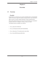
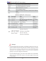
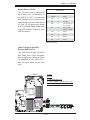
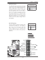
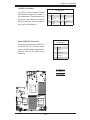
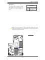
USB 4/5
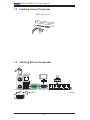
Front-panel accessible USB Connections
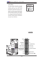
USB 6
Type A USB Embedded Drive Connector
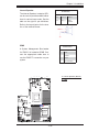
USB 7
USB Embedded Drive Connector
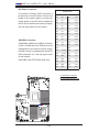
UID
UID (Unit Identifier) Switch
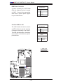
UIOP
Universal I/O Add-on Card Power Header (See the Warning
below.)
VGA
VGA Port
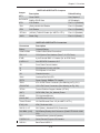
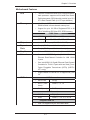
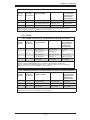
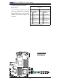
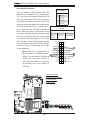
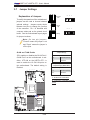
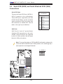
X8DTU-6F+/X8DTU-6TF+ LED Indicators
LED
Description
State
Status
LED 1
Power LED
Green: On
PWR On
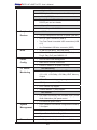
LED 2
UID LED
Blue: Solid On (from UID Switch), Unit IdentiBlinking (from IPMI)
fied
LED 3
BMC Heartbeat LED
Green: Blinking
BMC Normal
LED 4
SAS Activity LED
Blinking
SAS Active
LED 5
SAS Heartbeat LED
Blinking
SAS Normal
LED 6
SAS Error LED
On
SAS Errors
Occurred
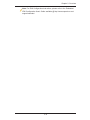
10Gb Link: Green On
LED7
10Gb LAN Dual-port
LED (Up: TLAN1,
Bottom: TLAN2)
10Gb Active: Green Blinks
1Gb Link: Yellow On
1Gb Active: Yellow Blinks
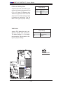
Warnings!
•
To avoid damaging the power supply or motherboard, please use a power supply that contains a 24-pin and two 8-pin power connectors. Be sure to connect
these connectors to the 24-pin (JPW1) and the two 8-pin (JPW2,JPW3) power
connectors on the motherboard. Failure to do so will void the manufacturer
warranty on your power supply and motherboard.
•
To provide adequate power to the add-on cards installed on the motherboard,
please connect the UIOP PWR connector to the power supply for these cards
to work properly.
2-6