1
English
EX
EX--44271
EX--44071 / EX
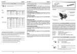
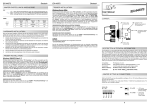
JUMPER SETTING & CONNECTORS:
J6:
DB 9M:
1 +5V
2 GND
3 GND
4 +12V
English
EX
EX--44271
EX--44071 / EX
DRIVER INSTALLATION :
For aux power (JP2) J6 must be connected to pc power supply !
If not, the card wont work.
Serial 9 Pin D-SUB connector:
Pin
Signal
Pin
Signal
Pin
Signal
1
CDC
4
DTR
7
RTS
2
RXD
5
GROUND
8
CTS
3
TXD
6
DSR
9
RI
HARDWARE INSTALLATION :
If you are ready with the jumper settings, please proceed with the following installation
instructions. Because the designs of computers are different, only general installation
instructions are given. Please refer your computer’s reference manual whenever in doubt.
1. Turn off the power to your computer and any other connected peripherals.
2. Remove the mounting screws located at the rear and/or sides panels of your Computer and gently slide the cover off.
3. Locate an available expansion slot and remove its covers from the rear panel of your
computer. Make sure it is the right expansion slot for the card (see card description)
4. Align the card with the expansion slot, and then gently but firmly, insert the card.
Make sure the card is seated and oriented correctly. Never insert the card by force!
5. Then connect the card with a screw to the rear panel of the computer case.
Windows Server 200x:
After starting Windows it recognizes a new “PCI Controller“ and opens the hardware
assistant. Please choose manual installation and put the driver CD into your CD-Rom
drive. Now enter the Path "D:\IO\OXFORD2\" and then the directory of your operating
system for Server 2000: “2000“ for Server 2003: “XP32“ or “XP64“ and for Server
2008: “VISTA32“ or “VISTA64“ into the box for the Path/Source and click at >next/
continue<. Now Windows search for the drivers in the specified directory. Follow the
hardware assistant and finish the installation. If Windows recognizes other new devices
repeat the above described steps. Attention! Restart Windows in any case after installing the drivers.
Bedienungsanleitung
Vers. 1.2 / 23.07.10
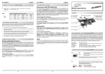
AUFBAU :
S1
Interner Serieller
Anschluss
CHECK THE INSTALLED DRIVER:
JP2 Jumper für die Stromquelle (Netzteil oder
PCI-Express Bus)
Click at Start<>Run< then enter “compmgmt.msc“ and click at >OK<. In the windows
that open select >Device Manager<. Under „Ports (COM and LPT)“ you should find
one or more new ”PCI Ports“ as sample (LPT2) or (Com3). If you see this or similar
entries the card is installed correctly.
J6
Anschluss für Power
vom PC Netzteil
CHANGE PORT NUMBER:
If you like to change the port number for example COM 3 to COM5, open the >Device
Manager< click at >COM3<, >Settings< and then >Advance<. There you can change
between COM 3 till 256.
LINUX:
There are no drivers available for Linux, but the card is supported by the most versions
of Linux. Because each individual distribution and kernel version of Linux is different,
sadly we cant provide a installation instruction. Please refer to the installation manual
for standard IO ports from your Linux version! In some newer versions the card will
even be installed automatically after starting Linux.
S1 9 Pin Stecker
Serieller Anschluss
JP3 Power auf 9 Pin Stecker Ein/Aus
BESCHREIBUNG & TECHNISCHE DATEN :
Die EX-44071 / EX-44271 ist eine PCI-Express serielle RS-232 Karte mit 1 seriellem
FIFO 16C95x Port, für den Anschluss von High-Speed seriellen RS-232 Peripherie
Geräten (z.B. Terminal, Modem, Plotter usw.). Der serielle PCI-Express Bus unterstützt
dabei optimal die Leistung des schnellen 16C95x Chipset mit 128byte FIFO Cache. Die
EX-44071 / EX-44271 gewährleistet so eine sichere Datenübertragung und exzellente
Performance von bis zu 921KBaud/s für jedes angeschlossene Gerät! Sie unterstützt
alle PCI-Express Slots von x1 bis x16. Es ist nicht möglich die I/O Adressen und Interrupts manuell einzustellen, da die Einstellungen der Karte vom System (BIOS) und
beim Installieren des Betriebssystems automatisch vorgenommen werden. Mit dem
Jumper JP2 & JP3 können Sie 12V oder 5V auf Pin9 des seriellen Anschlusses leiten.
Achten Sie bitte darauf dass die Angeschlossenen Geräte dies auch unterstützen. Bei
der EX-44271 handelt es sich um eine Low Profile Karte mit 8cm Slotblech.
6. Gently replace your computer’s cover and the mounting screws.
DRIVER INSTALLATION :
Windows 2000/XP/Vista & 7:
After starting Windows it recognizes a new “PCI Controller“ and opens the hardware
assistant. Please choose manual installation and put the driver CD into your CD-Rom
drive. Now enter the Path "D:\IO\OXFORD2\" and then the directory of your operating
system “2000“ “XP32“ “XP64“ “Vista32“ “Vista64“ “Win7_32bit“ or “Win7_64bit“
into the box for the Path/Source and click at >next/continue<. Now Windows search
for the drivers in the specified directory. Follow the hardware assistant and finish the
installation. If Windows recognizes other new devices repeat the above described
steps. Attention! Restart Windows in any case after installing the drivers.
Kompatibilität:
Betriebs Systeme:
Anschlüsse:
Lieferumfang:
PCI Express x1 bis x16
Win 2000/XP/Vista/7/Server 2000/2003/2008/Linux
1 x 9 Pin Sub-D Stecker
EX-44071 oder EX-44271, Treiber CD, Anleitung
Click at Start<>Run< then enter “compmgmt.msc“ and click at >OK<. In the windows
that open select >Device Manager<. Under ”Ports (COM and LPT)“ you should find
one or more new ”PCI Ports“ as sample (LPT2) or (Com3). If you see this or similar
entries the card is installed correctly.
Zertifikate:
CE / FCC / RoHS / WEEE
CHANGE PORT NUMBER:
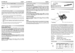
JP2:
CHECK THE INSTALLED DRIVER:
DE97424562 / WHQL
JUMPER EINSTELLUNG & ANSCHLÜSSE:
If you like to change the port number for example COM 3 to COM5, open the >Device
Manager< click at >COM3<, >Settings< and then >Advance<. There you can change
between COM 3 till 256.
Wenn sie den Jumper JP3 für S1 bis S2 auf PWR gesetzt haben, können sie mit dem JP2 den Spannungswert einstellen. Es gibt 3 verschiedene Spannungsquellen. (Nur in Verbindung mit JP3 auf PWR!!!)
X5V
X12V
I12V
JP3:
DIS PWR
S1
X 5V
X 12V
I 12V
= 5Volt vom PC-Netzteil
= 12Volt vom PC-Netzteil
= 12Volt vom Mainboard (STANDARD)
DIS
= Am Pin 9 liegt das Standard Signal RI (Ring Indicator).
(Werkseinstellung)
= Am Pin 9 kann jetzt eine Spannung von DC5V oder DC12V
eingestellt werden.
PWR
Die Einstellung der Spannung nehmen sie mit JP2 vor. Dieser sollte
aber bei Standard Anwendungen nicht verstellt werden.
5
6
1
Deutsch
EX
EX--44271
EX--44071 / EX
JUMPER EINSTELLUNG & ANSCHLÜSSE:
J6:
1 +5V
2 GND
3 GND
4 +12V
DB9M:
TREIBER INSTALLATION :
Windows Server 200x:
Für X5V oder X12V Einstellung (JP2) muss J6 mit dem PC Netzteil
verbunden werden! Sonst wird die Karte nicht mit Strom versorgt.
Seriell 9 Pin D-SUB Stecker :
Pin
Signal
Pin
Signal
Pin
Signal
1
CDC
4
DTR
7
RTS
2
RXD
5
GROUND
8
CTS
3
TXD
6
DSR
9
RI
HARDWARE INSTALLATION :
Wenn Sie die Karte installieren, beachten Sie bitte die folgenden Hinweise. Da es grosse
Unterschiede bei Computern gibt, können wir Ihnen nur eine generelle Anleitung zum
Einbau geben. Bei Unklarheiten halten Sie sich bitte an die Bedienungsanleitung Ihres
Computersystems.
1.
2.
3.
4.
5.
6.
Deutsch
EX
EX--44271
EX--44071 / EX
Schalten Sie Ihren Rechner und alle angeschlossenen Peripheriegeräte aus und
ziehen Sie bei allen Geräten den Netzstecker.
Lösen Sie die Schrauben des Gehäuses auf der Rückseite Ihres Computers und
entfernen Sie vorsichtig das Gehäuse.
Suchen Sie einen freien Steckplatz und entfernen sie das Slot Blech, stecken Sie die
Karte vorsichtig in den ausgewählten Steckplatz ein. Stellen sie sicher das es sich um
den richtigen Steckplatz handelt! (siehe Kompatibilität unter technische Daten)
Beachten Sie, das die Karte korrekt eingesteckt wird und das kein Kurzschluss entsteht. Wenden sie keine Gewalt an um die Karte einzustecken!
Danach befestigen Sie die Karte bitte mit einer Schraube am Gehäuse.
Jetzt können das Computergehäuse mit den Schrauben wieder schliessen.
Windows erkennt beim Start einen neuen “PCI Controller“ und öffnet automatisch den
Windows Hardwareassistenten. Wählen sie die manuelle Installation aus und legen Sie
die Treiber CD in Ihr CD-ROM Laufwerk (z.B. Laufwerk D:). Geben sie nun den Pfad
"D:\IO\OXFORD2\" und dann das Verzeichnis ihres Betriebssystems für Server 2000:
“2000“ für Server 2003: “XP32“ oder “XP64“ und für Server 2008: “VISTA32“ oder
“VIST64“ in das jeweilige Feld für die Quelle/Pfad ein und klicken sie auf >weiter<.
Windows sucht nun nach den Treibern in dem angegebenen Verzeichnis. Folgen sie
den Anweisungen des Hardwareassistenten und beenden sie die Installation. Sollte
Windows noch weitere neue Hardware erkennen wiederholen sie die oben angegebenen Schritte. Wichtig! Starten Sie Windows in jedem Fall nach der Installation neu.
User Manual
Vers. 1.2 / 23.07.10
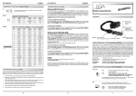
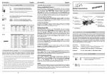
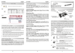
LAYOUT :
S1
Internal Header
connector
JP2 Select the power over
Power Supply or
PCI-Express Bus
ÜBERPRÜFEN DER INSTALLIERTEN TREIBER:
Klicken Sie auf Start<>Ausführen< geben sie “compmgmt.msc“ ein und klicken sie
auf >OK<. Wählen sie nun >GeräteManager<. Dort müssten Sie unter „Anschlüsse
(COM und LPT)“ einen oder mehrere neue “PCI Ports“ z.B. (LPT2) oder (Com3)
sehen. Wenn Sie diese oder ähnliche Einträge sehen, ist die Karte korrekt installiert.
J6 Aux. Power
Connector
ÄNDERN DER PORT NUMMER:
Hier können sie die Ports ändern, klicken sie z.B. auf >COM3< >Anschlusseinstellung< und
>Erweitert<. Sie können Sie dann zwischen Com3 und 256 wählen!
LINUX:
Es gibt für diese Karte keine Linux Treiber, sie wird allerdings unter den meisten Linux
Versionen unterstützt. Da sich die einzelnen Distributionen und Kernelversionen sehr
von einander unterscheiden können wir ihnen leider hier keine Installationsanweisung
geben. Bitte halten sie sich an die Installationsanweisung für Standard IO Ports ihrer
Linux Version. In einigen Versionen wird die Karte automatisch beim Start Installiert.
S1 9 pin male
serial connector
JP3 Enable the power to the 9 pin connector
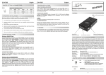
DESCRIPTION & TECHNICAL INFORMATION :
The EX-44071 / EX-44271 is a plug & play high-speed serial RS-232 expansion card
for the PCI Express Bus. The EX-44071 / EX-44271 provides one 9 pin high speed RS232 serial port. It uses data transfer rates up to 921Kbaud/s. The EX-44071 / EX-44271
design utilizes the 16C95x UART with 128byte buffer, which incorporates the latest in
high speed interface technology. In combination with the fast PCI-Express bus it provides a secure and very high data transfer on each port. It supports all PCI-Express
slots x1 to x16. It is not possible to change the address or IRQ settings manually, they
will be obtained automatically by the system BIOS and operating system. With the
jumper JP2 & JP3 you can enable power to pin 9. Please note if you use power to pin 9
your peripheral device must support it. The EX-44271 is a low profile card.
TREIBER INSTALLATION :
Windows 2000/XP/Vista & 7:
Windows erkennt beim Start einen neuen “PCI Controller“ und öffnet automatisch den
Windows Hardwareassistenten. Wählen sie die manuelle Installation aus und legen Sie
die Treiber CD in Ihr CD-ROM Laufwerk (z.B. Laufwerk D:). Geben sie nun den Pfad
"D:\IO\OXFORD2\" und dann das Verzeichnis ihres Betriebssystems “2000“ “XP32“
“XP64“ “Vista32“ “Vista64“ “Win7_32bit“ oder “Win7_64bit“ in das jeweilige Feld
für die Quelle/Pfad ein und klicken sie auf >weiter<. Windows sucht nun nach den
Treibern in dem angegebenen Verzeichnis. Folgen sie den Anweisungen des Hardwareassistenten und beenden sie die Installation. Sollte Windows noch weitere neue
Hardware erkennen wiederholen sie die oben angegebenen Schritte. Wichtig! Starten
Sie Windows in jedem Fall nach der Installation neu.
ÜBERPRÜFEN DER INSTALLIERTEN TREIBER:
Compatibility:
Operating system:
Connections:
Extent of delivery:
PCI Express x1 to x16
Win 2000/XP/Vista/7/Server 2000/2003/2008/Linux
1 x 9 Pin D-SUB serial male connector
EX-44071 or EX-44271, Driver CD, Manual
Certificates:
CE / FCC / RoHS / WEEE
DE97424562 / WHQL
JUMPER SETTING & CONNECTORS:
Klicken Sie auf Start<>Ausführen< geben sie “compmgmt.msc“ ein und klicken sie
auf >OK<. Wählen sie nun >GeräteManager<. Dort müssten Sie unter „Anschlüsse
(COM und LPT)“ einen oder mehrere neue “PCI Ports“ z.B. (LPT2) oder (Com3)
sehen. Wenn Sie diese oder ähnliche Einträge sehen, ist die Karte korrekt installiert.
Only if JP3 is set to PWR! The pin 9 from the serial port connector will
be supplied with DC5V or DC12V. There are 3 sources depending on
the jumper position of JP2.
JP2:
X5V
X12V
I12V
ÄNDERN DER PORT NUMMER:
Hier können sie die Ports ändern, klicken sie z.B. auf >COM3< >Anschlusseinstellung< und
>Erweitert<. Sie können Sie dann zwischen Com3 und 256 wählen!
X5V
X12V
I12V
JP3:
DIS PWR
S1
=
=
=
DC5V from J6, pc power supply connection is required
DC12V from J6, pc power supply connection is required
DC12V from PCI Express (Factory setting) J6 no cable
DIS
= The pin 9 is connected with the RI (Ring Indicator)
signal as standard RS-232 definition (Factory setting).
PWR
= The pin 9 is connected with a power either from PCI
Express slot or from Aux Power connector (J6)
The power source is controlled by JP2 jumper.
2
3
4