1
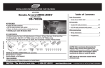
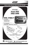
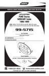
KIT FEATURES
5
ISO-DIN
head unit
provisions
Incorporates
factory climate
controls into
installation
Fig. A
(located under
the rear deck)
99-5716
INSTALLATION
INSTRUCTIONS
Fig. B
KIT COMPONENTS
APPLICATIONS
Open the trunk, remove (4) pop-clips from the driver's side trunk liner and remove the liner.
(see Fig. A). Locate the factory tuner on the wall of the trunk and disconnect the speaker and
antenna plugs (it is NOT necessary to remove the tuner). (see Fig. B). Plug the 70-5715 into
the unit speaker plug and the antenna extension lead into the unit antenna plug. Slide the
extension harness through the space in the back seat between the seat back and seat bottom.
Unclip the rocker trim, tuck the extension harness under the carpet and stretch the harness to
the back of the dash. (Replace the rocker trim when completed). Splice the speaker leads on
the extension harness into the rear of the aftermarket head unit. Plug the factory wiring
harnesses into the switch connectors (previously mounted in step #2) and audio connectors
on the back of the Integrated Mounting Kit.
6
Integrated
Mounting Kit
ISO Faceplate
CAR
PAGE
FORD
Taurus 2000-2003..................................................1-3
MERCURY
Sable 2000-2003.....................................................1-3
Extension
ISO Brackets
(2) #8 x 3/8"
Phillips Pan-head Screws
TOOLS REQUIRED
Re-connect the battery terminal and test the unit, climate controls and rear defroster for proper
operation. Snap the Integrated Mounting Kit assembly into the sub-dash.
3
rev. 03/08/07
INST99-5716
86-5618 - Head unit
removal keys
Torx-head screwdriver
©
1-800-221-0932
www.metraonline.com
COPYRIGHT 2001 METRA ELECTRONICS CORPORATION
3
ALL VEHICLES
Fig. B
1
Fig. A
Disconnect the negative battery terminal to prevent an accidental short circuit. Using Metra's
86-5618, pull the factory radio/climate control panel from the dash. Disconnect the audio
system connectors, blower motor switch connector, vacuum hose harness, a/c damper door
switch connector, and potentiometer connector. Remove the panel.
2
Remove (2) torx-head screws securing the mounting clips to the sides of the factory
radio/climate control panel and remove the clips. (see Fig. A). Mount the clips to the
Integrated Mounting Kit with the same torx-head screws. (see Fig. B)
4
Fig. A
Fig. A
Fig. B
Fig. B
Fig. D
Fig. C
Turn the factory climate control dials into a vertical position and pull the dials off. (see Fig. A).
Remove (2) 5/16" hex-head screws securing the temperature and fan control switches and
remove the switches. Unclip the climate control switch and remove the switch. (see Fig. B).
Mount the switches to the back of the Integrated Mounting Kit with (2) #8 x 3/8" Phillips Panhead Screws supplied. (see Fig. C). Holding the climate control dials in a vertical position,
insert the dials onto the posts of the mounted switches and secure. (see Fig. D)
1
ISO HEAD UNITS: Snap the ISO Faceplate into the radio opening. Attach the ISO Brackets
to the inner lip of the radio opening. Slide the head unit into the radio opening, align the holes in
the head unit with the holes in the ISO Brackets and mount the unit to the brackets with the
screws supplied with the unit. (see Fig.A).
DIN HEAD UNITS: Slide the DIN cage into the Integrated Mounting Kit and secure by
bending the metal locking tabs down. Slide the aftermarket head unit into the cage and
secure. (see Fig. B)
2