1
d. Connect an appropriate multimode or single-mode fiber cable to the fiber port of
the installed module. It is important to ensure that the transmit (TX) is attached to
the receive side of the device at the other end and the receive (RX) is attached to
the transmit side. Single-fiber (SF) media converter models operate in pairs. The
TX wavelength must match the RX wavelength at the other end and the RX
wavelength must match the TX wavelength at the other end.
3) VERIFY OPERATION
Once the module has been installed and configured per steps 1 and 2, verify the
module is operational by viewing the LED indicators.
The Power LED indicates the module is receiving power.
The Fiber Optic link LED indicates the fiber optic connection has been established.
The Coax LED indicates a T3/E3 signal has been detected.
Function
"Legend"
Color
OFF State
ON / Blinking state
Power
"Pwr"
Amber No Power
On: Power available
Fiber Activity
"Act"
Green No valid data
Fast blink (10Hz): Data Received
Fiber AIS
"AIS"
Amber
Fiber Test detected
"TST"
Fiber Loopback
"FLB"
Amber
--
No Test Data
Received
Fast blink (10Hz): AIS Received.
Local unit asserting Remote Loopback:
Fast blink (10Hz): Test pattern received.
Slow blink (1 Hz): Unexpected pattern received.
Special Case:
Three quick blinks (2Hz) and pause (1sec.):
Illegal dip-switch selection.
ON: Local Fiber Loopback.
If "CLB" also "ON" indicates that the unit is the
Local Unit in Remote Loopback Mode.
Slow blink (1Hz) and also "CLB" in slow blink:
indicates that the unit is the Remote Unit in
Remote Loopback Mode.
Amber Normal
Coax Loopback
"CLB"
Amber Normal
ON: Local Coax Loopback.
If "FLB" also "ON" indicates that the unit is the
Local Unit in Remote Loopback Mode.
Slow blink (1Hz) and also "FLB" in slow blink:
indicates that the unit is the Remote Unit in
Remote Loopback Mode.
Coax Activity
"ACT"
Green No valid data
Fast blink (10Hz): Data Received
Coax AIS detected
"AIS"
Amber
--
Fast blink (10Hz): AIS Received.
Coax PRBS detected
"PRBS"
Amber
--
Blink 10 Hz: PRBS Received.
Blink 1 Hz: Forcing PRBS onto BNC-Out.
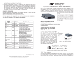
iConverter® T3/E3 Plugin Module USER MANUAL
The iConverter T3/E3 media converter provides standard T3 (44.736Mbps) or E3
(34.368Mbps) coax to fiber conversion and can be used to connect to devices such
as PBXs, multiplexers, routers and video
servers via fiber. T3/E3 media converters
operate in pairs, extending distances over
fiber, which improves noise immunity,
quality of service, intrusion protection and
network security.
The T3/E3 supports Small Form Pluggable
(SFP) transceivers, enabling adaptability
to different fiber types, distances and
wavelengths, providing maximum flexibility
across a variety of network architectures
and topologies.
Management of the plug-in module is accomplished by using a Management Module1
(such as an iConverter NMM2 or 10/100M2) that provides monitoring, configuration
and trap notification.
INSTALLATION PROCEDURE
1) Configure DIP-Switches
2) Install Module in the Chassis and Connect Cables
3) Verify Operation
1) CONFIGURE DIP-SWITCHES
FRONT PANEL DIP-SWITCHES
“FLB” - Fiber Loopback
This DIP-switch facilitates the testing of
the fiber cables. When the “FLB”
DIP-switch is in the ON position, it sets
the fiber port to a Local Fiber Loopback
Mode (Figure B) and the “FLB” LED is
turned on. When in this mode, data
received at the Fiber-In is forwarded to
the BNC-Out and the Fiber-Out. If no
Figure A: DIP-Switch Location
data is received at Fiber-In, an AIS
pattern is transmitted out both BNC-Out and Fiber-Out. By returning the
DIP-switch to the OFF position, the unit resumes normal operation.
1
For complete management support, use a M2 series module (NMM2, GX/TM2, 2GXM2,
10/100M2, 2FXM2) or higher. The T3/E3 SFP (8759-0) module must be at rev xx/10 or greater.
Figure B: Fiber Loopback and DIP-Switch Settings
Form 040-08740-002 B 7/09
Omnitron Systems Technology * 140 Technology Dr. #500 * Irvine, CA 92618
949.250.6510 tel * 949.250.6514 fax * www.omnitron-systems.com
ON-BOARD DIP-SWITCHES
ON
T3
E3
STS-1
>225
CDIS
FDIS
PRBS
---
This DIP-switch facilitates the testing of the coax cables. When the “CLB” DIP-switch
is in the ON position, it sets the coax port to a Local Coax Loopback Mode (Figure C)
and the “CLB” LED is turned on. When in this mode, data received at the BNC-In is
forwarded to the BNC-Out and the Fiber-Out. If no data is received at BNC-In, an AIS
pattern is transmitted out both BNC-Out and Fiber-Out. By returning the DIP-switch to
the OFF position, the unit resumes normal operation.
OFF
OFF
OFF
OFF
<225
CEN
FEN
OFF
---
“CLB” - Coax Loopback
Figure E: Board Mounted DIP-Switches
Figure C: Coax Loopback and DIP-Switch Settings
“FLB” + “CLB” - Remote Loopback Mode
When both the “FLB” and “CLB” DIP-switches are in the ON position, they force the
remote unit at the other end of the fiber link to loop back its fiber and coax ports (Figure
D). This facilitates test of the fiber cables and the remote unit without having to physically
set DIP-switches on the remote unit. While in this mode, the local unit’s BNC is set to
a local loopback, and its “FLB” and “CLB” LEDs are turned on.
“T3”, “E3” and “STS-1” - Select Protocol
When the “T3” DIP-switch is in the ON position, the T3 protocol is selected. When the
“E3” DIP-switch is in the ON position, the E3 protocol is selected. When the “STS-1”
DIP-switch is in the ON position, the STS-1 protocol is selected.
Only one of the three DIP-switches may be in the ON position at any one time. The
default setting of the module is T3.
“<225”/“>225” - Coax Build-Out Distance
While in the remote loopback mode, the local unit sends a test pattern to the remote
unit. This pattern forces the remote unit into the loopback mode and is also returned
back to the local unit. When forced into the remote loopback mode, the remote unit’s
“FLB” and “CLB” LEDS blink slowly (1Hz).
When this DIP-switch is in the OFF position, a distance of less than 225 ft. is selected.
When in the ON position, a distance of 225 ft. or higher is selected. Select the
appropriate distance for your application.
When the test pattern is received successfully at the local unit’s Fiber-In, the “TST”
LED blinks rapidly (10Hz). Any other data causes slow blinking (1Hz) on the “TST”
LED. If no data is returned to Fiber-In, the LED is turned OFF.
When both DIP-switches are in the OFF position, the ports are enabled. When the
“CEN”/”CDIS” is in the ON position, the coax port is disabled. When the “FEN”/”FDIS”
is in the ON position, the fiber port is disabled.
Returning both DIP-switches to the OFF position, causes the local and remote units to
resume normal operation.
“PRBS” - Pseudo Random Pattern Generator
“CEN”/“CDIS” and “FEN”/“FDIS” - Port Control
When in the ON position, the converter forces Pseudo Random pattern out of the
Coax-Out port. The data received at Fiber-In is discarded and the data at Coax-In is
passed through to Fiber-Out.
Note: Some combinations of DIP-switch settings are illegal, and will be indicated
by the Fiber Test “TST” LED blinking quickly three times followed by a pause.
2) INSTALL MODULE IN CHASSIS AND CONNECT CABLES
Figure D: Remote Loopback and DIP-Switch Settings
“FAIS” - Force 1s to Fiber (AIS)
When the “FAIS” DIP-switch is in the ON position, an “all ones” pattern is forced out
the Fiber-Out port. The Coax-In data is discarded and Fiber-In data is passed through
to BNC-Out. By returning the DIP-switch to the OFF position, the unit resumes normal
operation.
“CAIS” - Force 1s to Coax (AIS)
When the “CAIS” DIP-switch is in the ON position, an “all ones” pattern is forced out
the BNC-Out port. The Fiber-In data is discarded and BNC-In data is passed through
to Fiber-Out. By returning the DIP-switch to the OFF position, the unit resumes normal
operation.
a. Carefully slide the module into an open slot in the chassis. Align the module with
the installation guides and ensure that the module is firmly seated against the
backplane. Secure the module by fastening the front panel thumbscrew (push in
and turn clockwise to tighten) to the chassis front. Verify the “Pwr” LED is ON
(indicating the chassis is powered).
b. When using the SFP model (8759-0), insert the SFP Fiber transceiver into the Port
1 SFP receptacle on the T3/E3 converter (see the SFP Data Sheet 091-17000-001
for supported transceivers).
NOTE: The release latch of the SFP Fiber transceiver must be in the closed
(up) position before insertion.
c. Connect the BNC cables to the T3/E3 converter and attach the other end of the
cables to appropriate network equipment. The Transmit must attach to the Receive
and the Receive must attach to the Transmit.