1
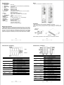
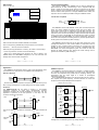
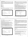
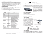
CTC Union Technologies Co.,Ltd.
Far Eastern Vienna Technology Center
(Neihu Technology Park)
8F, No. 60 Zhouzi St., Neihu, Taipei 114,
Taiwan
T +886-2-26591021
F +886-2-26590237
E [email protected]
[email protected]
[email protected]
H www.ctcu.com
2010 CTC Union Technologies Co., LTD.
All trademarks are the property of their respective owners.
Technical information in this document is subject to
change without notice.
User Guide
2.7G MultiRate 3R Transponder
FRM220-2.7G-2S & FRM220-2.7G-3S
Table of Contents
Introduction
Specifications
Management Features
Panel/Installation
LED Indicators (2S)
LED Indicators (3S)
DIP Setting
Loop Back Diagnostics
Application – Extender/Protection
Application - CWDM
Console Management
Upgrading
About SFP Units
------- 1
------- 2
------- 2
------- 3
------- 4
------- 5
------- 6
------- 7
------- 8
------- 9
------- 10-12
------- 13
------- 13
Introduction
The FRM220-2.7G-2S is a multi-rate, up to 2.7G 3R optical regeneration
device with clock data recovery (CDR). The "3R" consists of Reamplification, Re-shaping and Re-timing. The transponder card converts a
data signal to the correct wavelength for transmission on a specific channel
by supporting SFP optics on both line side and client side interfaces. When
the FRM220-2.7G-2S card is placed in the FRM220 rack with SNMP
management, the management can view the converter card's status, type,
version, fiber link status and alarms. The card can be configured to enable
or disable the port, reset the port, provide client or line side diagnostic
loopback, and set the desired data rate.
The FRM220-2.7G-3S is a multi-rate, up to 2.7G 3R optical regeneration
device with clock data recovery (CDR). The "3R" consists of Reamplification, Re-shaping and Re-timing. The transponder card converts a
data signal to the correct wavelength for transmission on a specific channel
by supporting SFP optics on both line side and client side interfaces. 1+1
Automatic optical line Protection Switching is supported for the aggregate
fiber ports. When the FRM220-2.7G-3S card is placed in the FRM220 rack
with SNMP management, the management can view the converter card's
status, type, version, fiber link status and alarms. The card can be
configured to enable or disable the port, reset the port, provide client or line
side diagnostic look back, and set the desired data rate.
The SFP sockets support a wide range of SFP modules to address any
network situation.
Single-mode
Multi-mode
Multi-rate
Single fiber bi-directional
Coarse and Dense Wave Division Multiplexing (CWDM and DWDM)
Copper media
WARNING: Fiber optic equipment may emit laser or infrared light that can
injure your eyes. Never look into an optical fiber or connector port. Always
assume that fiber optic cables are connected to a laser light source.
Version 1.1 May 2010
-1w w w . C T C U . c o m
w w w . C T C U . c o m
Specifications
Panel
Optical Interface
Connector
Data rate
Duplex mode
Fiber
Distance
Wavelength
1+1 switch
Indications
Power
Input
Consumption
Dimensions
Weight
Temperature
Humidity
Certification
MTBF
Test Loops
Figure 1. Front Panel of FRM220-2.7G-2S and 3S
SFP cage
E3 (34.368Mb/s) to OC-48/STM-16 (2.48832Gbps)
Full duplex
Depends on SFP
Depends on SFP
Depends on SFP
<50ms (3S model only)
LED (PWR, Line Link, Client Link, Test, Loop back,
Port Active, Alarm)
(Card supports hot-swapping)
Card : 12VDC, Standalone : AC, DC options
<10W
155 x 88 x 23mm (D x W x H)
120g
0 ~ 50°C (Operating), -10 ~ 70°C (Storage)
10 ~ 90% non-condensing
CE, FCC, LVD, RoHS
65000 hrs (25°C)
Client Side LB (2S model)
Line Side LB (2S model)
Client & Line LBs (3S model)
FRM220-2.7G-2S
FRM220-2.7G-3S
Installation
Figure 2. Slide-in Card mounting of FRM220-2.7G-2S/3S
Management Features
Both models have an on-board 8 pole DIP Switch which can be used to
configure the devices for stand-alone operation. When placed in a standalone chassis, these devices also support a text based serial terminal with
an easy to use menu system for configuration. When placed in a managed
chassis, the card is configured and monitored through the chassis NMC
(network management controller) via console, Telnet, Web HTTP or SNMP.
Note: Due to higher current requirements and excessive heat dissipation, this
converter card can only be placed in the CH-02M, CH02-NMC or the full CH-20
chassis.
CH02M Chassis
AC, DC, 2AC,
2DC, or AD
CH02-NMC Chassis
AC, DC, 2AC, 2DC,
or AD
FRM220-CH20
Follow all ESD precautions when handling the card and SFP modules.
-2-
-3-
w w w . C T C U . c o m
w w w . C T C U . c o m
LED Indicators (2S Model)
LED Indicators (3S Model)
LINE
CLIENT
LED
PWR
(Green)
Link
(Green)
LBT
(Green)
Alarm
(Red)
Act
(Green)
Link
(Green)
LBT
(Green)
Alarm
(Red)
State
On
Flash
Off
On
Off
On
Off
On
Off
On
Off
On
Off
On
Off
On
Off
Status
Power on
During upgrade
No Power
Line Side Fiber link
Line Side Fiber no link
Line Loop Back Test Enabled
Line Loop Back Test Off
Tx Alarm from Line SFP
No Line SFP Alarm
Card is Active
Card is disabled
Client Side Fiber link
Client Side Fiber no link
Client Loop Back Test Enabled
Client Loop Back Test Off
Tx Alarm from Client SFP
No Client SFP Alarm
LED
MGT
(Green)
Act
(Green)
PWR
(Green)
Online
(Green)
Online
(Green)
LBT
(Green)
Link
(Green)
Link
(Green)
Link
(Green)
Alarm
(Red)
Alarm
(Red)
Alarm
(Red)
State
On
Off
On
Off
On
Flash
Off
On
Off
On
Off
On
Off
On
Off
On
Off
On
Off
On
Off
On
Off
On
Off
Status
In-rack management
no rack management
Card active
Card disabled
Power on
During upgrade
No Power
Secondary Online
Secondary Offline
Primary Online
Primary Offline
Line Loop Back Test Enabled
Line Loop Back Test Off
Secondary Fiber link
Secondary Fiber no link
Primary Fiber link
Primary Fiber no link
Line Fiber link
Line Fiber no link
Tx Alarm from Secondary SFP
No Secondary SFP Alarm
Tx Alarm from Primary SFP
No Primary SFP Alarm
Tx Alarm from Line SFP
No Line SFP Alarm
-4-
-5-
w w w . C T C U . c o m
w w w . C T C U . c o m
DIP Settings
Loop back Testing (LBT):
DIP Switch On PCB
The loopback capability of the FRM220-2.7G is useful for debugging a
dysfunctional link, or when commissioning a site. In loopback mode, the
signal is routed into the CDR circuitry and then routed back to the signal
source. Loopback may be enabled via DIP switch selection or management
terminal console. When placed in a managed FRM220-CH20 chassis, the
loop back can be controlled by the NMC manager in FRM220 chassis.
2.7G-3S Only
Dip Sw
2S
3S
1
Rate 1
Rate 1
2
Rate 2
Rate 2
3
Rate 3
Rate 3
4
Rate 4
Rate 4
2/3S
Off
On
Off
On
Off
On
Off
On
Off
On
Off
On
Off
Off
On
On
Off
Off
On
On
Off
Off
On
On
Off
Off
Off
Off
On
On
On
On
Off
Off
Off
Off
Off
Off
Off
Off
Off
Off
Off
off
On
On
On
On
5
6
LFP
ALS
LFP
ALS
Protocol Supported
E3
DS3/T3
OC-1/STM-0
Fast Ethernet
OC-3/STM-1
OC-12/STM-4
Fiber Channel-1
OC-24/STM-8
Gigabit Ethernet
HD-SDI
Fiber Channel-2
OC-48/STM-16
2.7G-2S Fiber Loop Back
7
8
X
X
Protect
Client
Fiber Data Rate
34.368Mbps
44.736Mbps
51.84Mbps
125Mbps
155.52Mbps
622.08Mbps
1.0625Gbps
1.24416Gbps
1.25Gbps
1.485Gbps
2.125Gbps
2.48832Gbps
Sw5 LFP Off=Link Fault Pass-thru disabled; On=enabled
Sw6 ALS Off=Auto Laser Shutdown disabled; On=enabled
Sw7 Forced (3S Only) Off=Manual (Forced) Protection; On=Automatic
Protection* * when On, Sw8 is not followed
Sw8 Path (3S Only) Off=Client is on Primary; On=Client is on Secondary**
** works only when Sw7 is Off for manual forced setting
Client
Loop Back
Line
Loop Back
The FRM220-2.7G-2S model features a front panel mounted 2-pole DIP
switch. This switch enabled loop back for either client or line fibers. The
upper switch, when turned on, enables the Line side fiber loop back. The
lower switch, when turned on, enables the Client side fiber loop back. The
loop back function can also be enabled by using a serial terminal connected
to the 9 pin D-Sub on the CH02M, via the terminal menu system. If placed
in FRM220-CH20 with NMC/SNMP, the chassis management system can
access the card and perform all setting functions. (The front panel switches
will be ignored and overridden by NMC manager.)
The FRM220-2.7G-3S model can only do loop back through one of the
management interfaces i.e. local console or NMC. The loop back function is
enabled by using a serial terminal connected to the 9 pin D-Sub on the
CH02M, via the terminal menu system. If placed in FRM220-CH20 with
NMC/SNMP, the chassis management system can access the card and
perform all setting functions. (The internal DIP switch settings will be
ignored and overridden by NMC manager.)
Notice: All of these settings are ignored if the card is placed in the
FRM220-CH20 with NMC/SNMP management. The card will follow the
settings done via the chassis management.
-6-
-7-
w w w . C T C U . c o m
w w w . C T C U . c o m
The FRM220-2.7G 3R repeater works in point-to-point applications, either
as a stand-alone or when placed in the FRM220-CH20 managed rack.
CWDM Transponder
The FRM220-2.7G functions primarily as a repeater or a media converter.
As a repeater for long-haul applications, the signal is fully regenerated at
the trunk. Clock Data Recovery (CDR) helps in reshaping, retiming, and
regenerating (3R) the output signal at a number of pre-assigned
frequencies or protocols.
In the CWDM/DWDM application, the 3R transponder acts as a fiber-tofiber repeater and optical frequency converter between the client side
equipment and the Optical Multiplexer/De-multiplexer.
Application
Extension Repeater
2S
2S
Client
Client
Line
Line
Set local and remote 3R repeater to the protocol's data rate either by local
DIP or through management. The rate setting is the only setting required.
Protection
The FRM220-2.7G-3S has the ability to provide 1+1, non-revertive
redundancy protection for single input, repeater/media converter
applications complete with full 3R capabilities on each trunk. This first
application of protection is line side protection. In this setup, the line
connector actually faces the client.
3S
Client
3S
PRI
FRM220-CH20 20-slot chassis
Client
1310 SFP
Line
1470 SFP
1470
Line
1490 SFP
1490
Line
1510 SFP
1510
Line
1530 SFP
1530
Client
1310 SFP
Client
Client
1550 SFP
LINE
SEC
Mux/Demux
WAN
PRI
LINE
2S
SEC
The second application provides for redundant clients and automatic fall
over.
3S
2S
PRI
CLIENT
Client
850 SFP
Client
Redundant
Clients
LINE
LINE
SEC
Set transponder to the protocol's data rate either by local DIP or through
management. The rate setting is the only setting required.
-8-
-9-
w w w . C T C U . c o m
w w w . C T C U . c o m
Console Management
When placed in the 2-slot CH02M chassis, this card can be locally
managed by connecting a simple serial terminal such as a notebook
computer that has an RS232 port or via a commonly available USB to
RS232 adapter. In Windows XP, HyperTerminal™ is an application
available for emulating a serial terminal. You can also search for TeraTerm
or PuTTY which are free alternatives, especially if the operating system is
Vista or Win7.
Settings
Baud Rate: 38,400
Data bits: 8
Parity bits: none
Stop bits: 1
Handshaking: none
Emulation: VT-100
Connect the serial cable to the CH02M's DB9. Run the terminal emulation
program. With power on, press [ESC], [space] or [Enter] to display the
"Main Menu" screen. The following is an example.
****************************************
*** CTC UNION TECHNOLOGIES CO.,LTD ***
*** FRM220 2.7G-2S Manager Ver:1.00 ***
****************************************
Version:[1.100-1.000-1.100-0.000]
[CH-02M Slot-1
Line Status[Down]
Client Status[Down]
<1> Port Active:
[Enable ]
<2> Baud Rate Select:
[Fast Ethernet
<3> Line Side Loopback Test:
[Off
]
<4> Client Side Loopback Test:
[Off
]
<5> Link Fault Pass-Through:
[Disable]
<6> Line Side Auto Laser Shutdown:
[Disable]
<7> Client Side Auto Laser Shutdown:
[Disable]
<D> D/D Function
<R> Port Reset
<S> Store Parameters
Please select an item.
Operation
Select any of the menu items by keying in the menu item number or letter.
Use the [ESC] to return to a previous menu. Any setting is immediately
applied to the transponder's circuitry. After all of the parameter settings
have been selected, press "s" from the main menu to save the parameters
in non-volatile RAM (NVR). To revert to previous settings before saving,
press "r" to reset (reload previously saved parameters).
Explanation of Settings
1. Port Active: This will enable or disable the card. When inactive, no
transmissions will be able to occur.
2. Baud Rate Select: This will bring up the data rate selection list. Select the
required 3R recovery speed by choosing the protocol.
3. Line Side LBT: This will activate the Line side loop back diagnostics
4. Client Side LBT: This will activate Client side fiber loop back diagnostics
5. LFP: Enables or Disables Link Fault Pass Through function
6. Line ALS: This can enable Auto Laser Shutdown protection for Line side
7. Client ALS: Can enable Client side Auto Laser Shutdown protection
D. D/D: Enables user to read the serial data stored in SFP module
R. Reset: This will cause the parameters settings in NVR to be reloaded
S. Store: Saves the setting parameters into non-volatile RAM (NVR)
Example of reading Digital Diagnostics in SFP
]
]
Example of Main Menu Console Screen, FRM220-2.7G-2S
D/D Function:
<1> Line Side D/D Function:
[Yes ]
<2> Client Side D/D Function:
[Yes ]
<ESC> Go to previous menu. Please select an item.
------------------------------------------------------------Client Side D/D Function:
Vendor Name
:[FIBERXON INC.
]
Vendor Part Number
:[FTM-6128C-L5051 ]
Fiber Type
:[Single ]
Tx Wave Length
:[1510 nm ]
RX Wave Length
:[1510 nm ]
Link Length
:[0050 Km ]
Tx Power
:[ -01 dBm]
Rx Power
:[ -41 dBm]
Rx Sensitivity
:[ 00 dBm]
Temperature
:[ 42 C ]
<ESC> Go to previous menu.
Parameters are read from any MSA compliant SFP module. Extended
information is only available in modules which support D/D function.
- 10 -
- 11 -
w w w . C T C U . c o m
w w w . C T C U . c o m
Repeater with Protection
There are additional menu items for the FRM220-2.7G-3S model to
control the behavior of the Pri. and Sec. fiber 1+1 behavior.
Upgrading
The FRM220-2.7G card may be firmware upgraded when it is placed in
the FRM220 with NMC management card. The user may use a local
console connection to the NMC, a remote Telnet (IP) connection, or a Web
based (HTTP) connection with any available browser. The NMC
communicates to all cards through a serial RS485 control bus. The upgrade
code is transferred to the NMC by way of TFTP server. All of these
mentioned upgrade methods are well documented in the FRM220-NMC
Software Operation Manual.
Explanation of Settings
1. Port Active: This will enable or disable the card
2. Baud Rate Select: This will bring up the protocol rate selection list
3. Fiber Protection: When set off, the fiber path is manually selected
through item 4's selection. When set on, the fiber will automatically take the
redundant path if working path fails (non-revertive)
4. Select Client Path: When item 3's protection is set to manual (off), this
setting will force the client's path as either 'Primary' or 'Secondary'
5. LBT: This will enable simultaneous Line and Client fiber loop back
6. LFP: Enables the Link Fault Pass Through action
7. Line ALS: This can enable/disable Auto Laser Shutdown for Line side
8. Primary ALS: Can enable/disable Primary side Auto Laser Shutdown
9. Secondary ALS: Can enable/disable Secondary side Auto Laser
Shutdown
D. D/D: Enables user to read the serial data stored in SFP module
R. Reset: This will cause the parameters settings in NVR to be reloaded
S. Store: Saves the setting parameters into non-volatile RAM (NVR)
****************************************
*** CTC UNION TECHNOLOGIES CO.,LTD ***
*** FRM220 2.7G-3S Manager Ver:1.00 ***
****************************************
Version:[1.100-1.000-1.100-0.000]
[CH-02M Slot-1 ]
Line Status[Down]
Primary Status[Down]
Secondary
Status[Down]
<1> Port Active:
[Disable]
<2> Baud Rate Select:
[Fast Ethernet ]
<3> Optic Fiber Protection:
[Off
]
<4> Select Client Master:
[Primary ]
<5> Loopback Test Function:
[Off
]
<6> Link Fault Pass-Through:
[Disable]
<7> Line Side Auto Laser Shutdown:
[Disable]
<8> Primary Side Auto Laser Shutdown:
[Disable]
<9> Secondary Side Auto Laser Shutdown: [Disable]
<D> D/D Function
<R> Port Reset
<S> Store Parameters
Please select an item.
About SFP Units
The FRM220-2.7G accepts any SFP unit that complies with the MSA
standard. Follow all ESD precautions when handling the card and SFP
modules. Fiber optic components and cables are very sensitive to dirt, dust
and mishandling, especially in high-speed networks. Dirty or mistreated
fiber may cause errors and an unwanted degradation of signal quality.
Remove the dust caps on SFP only when ready to plug in optical cables.
When choosing SFP optical modules, the SFP must be able to support
the required data rate. OC3 SFP (155M) will operate fine at STM-1 and Fast
Ethernet speeds, but not all modules will operate at lower speeds (E3, T3,
or STM-0). Make sure the SFP modules chosen are suitable for the
required data rate.
Installation
CTC Union supplied SFP modules are of the Bale Clasp type. The bale
clasp SFP module has a bale clasp that secures the module into the SFP
cage.
• Inserting a Bale Clasp SFP Module into a SFP cage
Step 1 Close the bale clasp upward before inserting the SFP module.
Step 2 Line up the SFP module with the port, and slide it into the cage.
• Removing a Bale Clasp SFP Module
Step 1 Open the bale clasp on the SFP module. Press the clasp
downward with your index finger.
Step 2 Grasp the SFP module between your thumb and index finger and
carefully remove it from the SFP cage.
Example of Main Menu Console Screen, FRM220-2.7G-3S
- 12 -
- 13 -
w w w . C T C U . c o m
w w w . C T C U . c o m