1
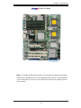
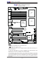
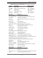
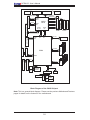
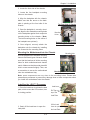
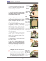
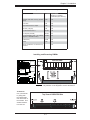
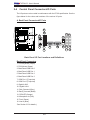
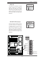
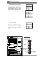
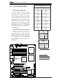
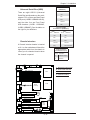
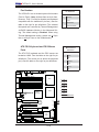
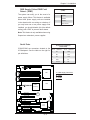
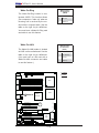
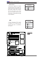
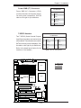
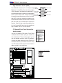
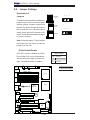
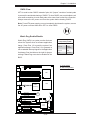
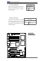
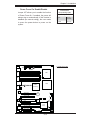
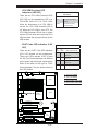
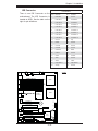
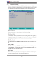
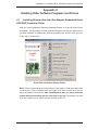
X7DAL-E+ User's Manual
2-5
ATX Power 20-pin Connector
Pin Definitions
Connecting Cables
ATX Power Connector
A 24-pin main power supply
connector(JPW1) and an 8-pin CPU
PWR connector (JPW3) are located
on the motherboard. These power
connectors meet the SSI EPS 12V
specification. The 4-pin 12V PWR
supply at JPW2 is required to provide
adequate power to the PCI-Express
slots. See the tables on the right for
pin definitions.
Processor Power Connector
Pin#
Definition
13
+3.3V
1
+3.3V
14
-12V
2
+3.3V
15
COM
3
COM
16
PS_ON
4
+5V
17
COM
5
COM
18
COM
6
+5V
19
COM
7
COM
20
Res (NC)
8
PWR_OK
21
+5V
9
5VSB
22
+5V
10
+12V
23
+5V
11
+12V
24
COM
12
+3.3V
C B
USB 0/1/2/3
LE2
PWR
Force-On
Ground
3 and 4
+12V
Definition
1 through 4
Ground
5 through 8
+12V
Required Connection
DIMM 4A (Bank 4)
2nd
Branch
DIMM 3A (Bank 3)
COM1
1 and 2
Pins
PWR
I2C
Definition
12V 8-pin Power CPU
Connector
Pin Definitions
Fan1
KB/
Mouse
Pins
A
24-Pin ATX PWR
Definition
12V 4-pin Power Connector
Pin Definitions
In addition to the Primary ATX power
connector (above), the 12V 8-pin CPU
PWR connector at JPW3 must also
be connected to your motherboard.
See the table on the right for pin
definitions.
4-Pin 8-Pin PWR
PWR
JPWF
Alarm
Reset
Pin #
CPU1
DIMM 2B (Bank 2)
DIMM 2A (Bank 2)
COM2
1st
Branch
DIMM 1B (Bank 1)
A. 24-pin ATX PWR
DIMM 1A (Bank 1)
B. 8-pin Processor PWR
LAN1/LAN2
CPU2
SUPER
®
X7DAL-E+
Fan5
Fan6
LAN
CTRLR
C. 4-pin Processor PWR
5000X
North Bridge
Slot6 PCI-E x16
LE3
Audio
Battery
Fan2
LE1
FP Audio
Audio
CTRL JPAC1
T-SGPIO2 T-SGPIO1
Slot4 PCI-E x4 on x16 slot
JL1
BIOS
Printer
D31
JBT1
JWD
Slot3 PCI-X 133 MHz
ESB2
CD-In
JPL1
JPL2
JWOR
JWOL
SATA1
Slot0 PCI-U
SATA3
LE4
LE5
JI2C2
JI2C1
Floppy
Slot1 PCI 33 MHz
SMB
JD1 USB4/5 USB6/7
SATA0
SATA2
South
Bridge
Slot2 PCI-X 133 MHz
S I/O
FP Control
Fan3
Slot5 PCI-33 MHz
SATA4
SATA5
Buzzer
IDE
2-14
Fan4