1
INSTALLATION INSTRUCTIONS
FSM SERIES
SMALL FLAT PANEL DISPLAY STATIC WALL MOUNT
Exclusive Q2™ Mounting System
Prior to assembly, unpack carton completely and verify contents.
If you are missing any of the following components, please contact Customer Service at 1-800/582-6480
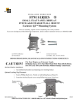
Figure 1
(1) FSM Wall Bracket
(2) Wood Screw
(4) Drywall Anchor
(4) Washer, Flat, .25 ID X .56 OD
BEFORE PROCEEDING, READ INSTALLATION INSTRUCTIONS COMPLETELY
CAUTION!
BEFORE PROCEEDING, READ INSTALLATION INSTRUCTIONS COMPLETELY
WARNING: IMPROPER INSTALLATION MAY RESULT IN SERIOUS PERSONAL INJURY!
When mounting Chief Manufacturing accessories, the structural system and mounting method
MUST be capable of supporting 5 times the combined weight of the total installation. The maximum
weight to be installed on the FSM is 45 pounds (20.4 Kg) in wood stud and 30 pounds (13.60 kg) in
drywall.
Flat Panel Displays are Extremely Fragile.
CAUTION!
If Monitor Uses a Screw Size Other Than M4 X 10mm (M4 X 20mm),
DO NOT USE M4 Screws Provided. Monitor Damage Could Occur.
Interface Bracket Installation:
1. See installation procedures accompanying your mounting bracket.
Optional Latching Flag Placement:
1. Remove Phillips head screw, Nylock nut and latching flag (see Figure 2).
2. Reposition latching flag and secure using Phillips head screw, Nylock nut.
Remove screw
and nut
Move latch
Figure 2
8804-000046 RevA
CHIEF MANUFACTURING INC. 1-800-582-6480, Fax: 1-877-894-6918, Email: [email protected]
2/28/07
CAUTION!
Minimum Sheetrock Thickness ½ Inch.
Drywall Installation Procedures:
1. Using the wall bracket as a template at the desired mounting location, mark the location of the four
outer mounting holes.
2. Using a 3/8-inch drill, drill four pilot holes to a minimum depth of 1 1/2” at the locations marked in
Step 1.
3. Install an anchor bolt in one of the pilot holes and tighten anchor bolt until it is fully seated (see
Figure 3).
4. Remove and retain bolt from anchor and repeat Step 3 and 4 for three remaining anchor bolts.
5. Install .25 ID X .56 OD flat washer on each of four bolts removed from anchors.
6. Using four bolts, with washers installed, secure wall bracket to wall.
Wood Stud Installation Procedures:
1. Locate stud and, using wall bracket as a template at the desired height, mark the location of the two
center mounting holes.
2. Install a flat washer on each of the two wood screws.
3. Using the two wood screws with flat washers installed, secure wall bracket to wall.
Mounting Display with Interface Bracket to Wall Bracket:
1. Make sure the latching flag on the mounting bracket is in the unlocked position (see Figure 4).
2. Place your small flat panel display; with interface bracket attached, onto the wall bracket, making
sure it is securely seated.
3. Lower the latching flag on the wall bracket, locking small flat panel display in place (see Figure 5).
#10-24 Screw
Anchor
O 0.375 (Predrill Hole)
%%c
0.375
(PREDRILL HOLE)
Locked
Unlocked
Outer Mounting Holes
INSERTANCHOR INTOPPREDRILLED HOLE
Insert anchor into
predrilled hole
Anchor Barb
(Stops anchor rotation)
ANCHOR BARBP(STOPS ANCHOR ROTATION)
Turn 10-24 screw clockwise
until anchor fully seats
against back side of wall
CW
CW
Center Mounting Holes
Figure 4
Figure 3
Figure 5