1
INSTALLATION INSTRUCTIONS
FSP SERIES
SMALL FLAT PANEL DISPLAY
SINGLE SCREEN POLE MOUNT
Exclusive Q2™ Mounting System
Prior to assembly, unpack carton completely and verify contents.
If you are missing any of the following components, please contact Customer Service at 1-800/582-6480.
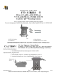
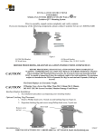
Figure 1
(1) FSP Pole-Mounting Bracket
(4) 10-24 x 1.00 Self-tapping Screws
(4) ½” X ½” Nylon Spacers
(1) 5/32” Hex Key
BEFORE PROCEEDING, READ INSTALLATION INSTRUCTIONS COMPLETELY
The FSP will fit on any 1/1/2” to 2” O.D. pipe including 1 ½”NPT.
CAUTION!
Flat Panel Displays are Extremely Fragile.
If Monitor Uses a Screw Size Other Than M4 X 10mm (M4 X 20mm),
DO NOT USE M4 Screws Provided. Monitor Damage Could Occur.
Interface Bracket Installation:
1. See installation procedures accompanying your mounting bracket.
Optional Latching Flag Placement:
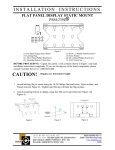
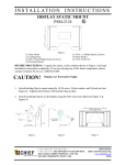
1. Remove Phillips head screw, Nylock nut and latching flag (see Figure 2).
2. Reposition latching flag and secure using Phillips head screw, Nylock nut.
8804-000047
01/04
CHIEF MANUFACTURING INC. 1-800-582-6480, Fax: 1-877-894-6918, Email: [email protected]
Remove screw
and nut
Move latch
Figure 2
Pole-Mounting Bracket Assembly and Installation:
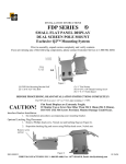
1. For vertical pole mounting, install the pole-mounting bracket on 1 ½” to 2” OD pipe/pole and secure
using two screws (see Figure 3) and hex key.
2. For horizontal pole mounting; remove four tilt adjustment screws, reposition the tilt bracket as shown
in Figure 4, and insert nylon spacers. Secure using 10-24 x 1.00 screws provided.
Mounting Display with Interface Bracket to Pole-Mounting Bracket:
1. Make sure the latching flag on the pole-mounting bracket is in the unlocked position (see Figure 3).
2. Place your small flat panel display; with interface bracket attached, onto the pole-mounting bracket,
making sure it is securely seated.
Unlocked
10-24 x 1.00 screws
.500 O.D. x .500 long
Nylon spacers
Figure 4
Figure 3
3. Lower pole-mounting bracket latching flag, locking small flat panel display in place (see Figure 5).
4. Adjust tilt by loosening (slightly) tilt adjustment screws (see Figure 6) on each side of pole-mounting
bracket, adjust to desired angle, and tighten tilt adjustment screws.
Tilt Adjustment Screws
Tighten
to
secure
to pole
Locked
Figure 5
Figure 6